EP0615810A2 - Partie d'aube et méthode pour former la jonction - Google Patents
Partie d'aube et méthode pour former la jonction Download PDFInfo
- Publication number
- EP0615810A2 EP0615810A2 EP93119872A EP93119872A EP0615810A2 EP 0615810 A2 EP0615810 A2 EP 0615810A2 EP 93119872 A EP93119872 A EP 93119872A EP 93119872 A EP93119872 A EP 93119872A EP 0615810 A2 EP0615810 A2 EP 0615810A2
- Authority
- EP
- European Patent Office
- Prior art keywords
- original base
- base component
- insert member
- insert
- members
- Prior art date
- Legal status (The legal status is an assumption and is not a legal conclusion. Google has not performed a legal analysis and makes no representation as to the accuracy of the status listed.)
- Granted
Links
- 238000004519 manufacturing process Methods 0.000 title claims description 7
- 238000009792 diffusion process Methods 0.000 claims abstract description 80
- 238000002844 melting Methods 0.000 claims abstract description 45
- 230000008018 melting Effects 0.000 claims abstract description 45
- 238000010438 heat treatment Methods 0.000 claims abstract description 44
- 238000003466 welding Methods 0.000 claims abstract description 13
- PXHVJJICTQNCMI-UHFFFAOYSA-N Nickel Chemical group [Ni] PXHVJJICTQNCMI-UHFFFAOYSA-N 0.000 claims description 29
- 238000000034 method Methods 0.000 claims description 23
- 229910052698 phosphorus Inorganic materials 0.000 claims description 18
- 229910052759 nickel Inorganic materials 0.000 claims description 17
- XEEYBQQBJWHFJM-UHFFFAOYSA-N Iron Chemical compound [Fe] XEEYBQQBJWHFJM-UHFFFAOYSA-N 0.000 claims description 12
- 239000013078 crystal Substances 0.000 claims description 11
- 229910052742 iron Inorganic materials 0.000 claims description 9
- OAICVXFJPJFONN-UHFFFAOYSA-N Phosphorus Chemical compound [P] OAICVXFJPJFONN-UHFFFAOYSA-N 0.000 claims description 8
- 239000011574 phosphorus Substances 0.000 claims description 8
- ZOXJGFHDIHLPTG-UHFFFAOYSA-N Boron Chemical compound [B] ZOXJGFHDIHLPTG-UHFFFAOYSA-N 0.000 claims description 6
- XUIMIQQOPSSXEZ-UHFFFAOYSA-N Silicon Chemical compound [Si] XUIMIQQOPSSXEZ-UHFFFAOYSA-N 0.000 claims description 6
- 229910052796 boron Inorganic materials 0.000 claims description 6
- 238000007747 plating Methods 0.000 claims description 6
- 229910052710 silicon Inorganic materials 0.000 claims description 6
- 239000010703 silicon Substances 0.000 claims description 6
- 239000012530 fluid Substances 0.000 claims description 4
- 230000003247 decreasing effect Effects 0.000 claims description 3
- 229910000975 Carbon steel Inorganic materials 0.000 claims 1
- 239000010962 carbon steel Substances 0.000 claims 1
- 229910018104 Ni-P Inorganic materials 0.000 description 52
- 229910018536 Ni—P Inorganic materials 0.000 description 52
- 230000006835 compression Effects 0.000 description 9
- 238000007906 compression Methods 0.000 description 9
- 229910018487 Ni—Cr Inorganic materials 0.000 description 7
- 238000005260 corrosion Methods 0.000 description 6
- 229910000734 martensite Inorganic materials 0.000 description 6
- 238000010791 quenching Methods 0.000 description 5
- 230000000171 quenching effect Effects 0.000 description 5
- 229910000831 Steel Inorganic materials 0.000 description 4
- 230000007797 corrosion Effects 0.000 description 4
- 239000003960 organic solvent Substances 0.000 description 4
- 239000010959 steel Substances 0.000 description 4
- 238000005496 tempering Methods 0.000 description 4
- 229910045601 alloy Inorganic materials 0.000 description 3
- 239000000956 alloy Substances 0.000 description 3
- 239000000203 mixture Substances 0.000 description 3
- 230000004323 axial length Effects 0.000 description 2
- 238000010586 diagram Methods 0.000 description 2
- 238000007772 electroless plating Methods 0.000 description 2
- 239000000843 powder Substances 0.000 description 2
- 238000003825 pressing Methods 0.000 description 2
- ZAMOUSCENKQFHK-UHFFFAOYSA-N Chlorine atom Chemical compound [Cl] ZAMOUSCENKQFHK-UHFFFAOYSA-N 0.000 description 1
- 229910001208 Crucible steel Inorganic materials 0.000 description 1
- 229910018098 Ni-Si Inorganic materials 0.000 description 1
- 229910018529 Ni—Si Inorganic materials 0.000 description 1
- 238000007664 blowing Methods 0.000 description 1
- 239000000460 chlorine Substances 0.000 description 1
- 229910052801 chlorine Inorganic materials 0.000 description 1
- 239000011248 coating agent Substances 0.000 description 1
- 238000000576 coating method Methods 0.000 description 1
- 238000007599 discharging Methods 0.000 description 1
- 238000005304 joining Methods 0.000 description 1
- 238000002156 mixing Methods 0.000 description 1
- 239000003921 oil Substances 0.000 description 1
- 239000013535 sea water Substances 0.000 description 1
- 238000009987 spinning Methods 0.000 description 1
- 230000003746 surface roughness Effects 0.000 description 1
- XLYOFNOQVPJJNP-UHFFFAOYSA-N water Substances O XLYOFNOQVPJJNP-UHFFFAOYSA-N 0.000 description 1
Images


Classifications
-
- B—PERFORMING OPERATIONS; TRANSPORTING
- B23—MACHINE TOOLS; METAL-WORKING NOT OTHERWISE PROVIDED FOR
- B23K—SOLDERING OR UNSOLDERING; WELDING; CLADDING OR PLATING BY SOLDERING OR WELDING; CUTTING BY APPLYING HEAT LOCALLY, e.g. FLAME CUTTING; WORKING BY LASER BEAM
- B23K20/00—Non-electric welding by applying impact or other pressure, with or without the application of heat, e.g. cladding or plating
- B23K20/02—Non-electric welding by applying impact or other pressure, with or without the application of heat, e.g. cladding or plating by means of a press ; Diffusion bonding
- B23K20/023—Thermo-compression bonding
-
- B—PERFORMING OPERATIONS; TRANSPORTING
- B23—MACHINE TOOLS; METAL-WORKING NOT OTHERWISE PROVIDED FOR
- B23K—SOLDERING OR UNSOLDERING; WELDING; CLADDING OR PLATING BY SOLDERING OR WELDING; CUTTING BY APPLYING HEAT LOCALLY, e.g. FLAME CUTTING; WORKING BY LASER BEAM
- B23K20/00—Non-electric welding by applying impact or other pressure, with or without the application of heat, e.g. cladding or plating
- B23K20/16—Non-electric welding by applying impact or other pressure, with or without the application of heat, e.g. cladding or plating with interposition of special material to facilitate connection of the parts, e.g. material for absorbing or producing gas
-
- F—MECHANICAL ENGINEERING; LIGHTING; HEATING; WEAPONS; BLASTING
- F04—POSITIVE - DISPLACEMENT MACHINES FOR LIQUIDS; PUMPS FOR LIQUIDS OR ELASTIC FLUIDS
- F04D—NON-POSITIVE-DISPLACEMENT PUMPS
- F04D29/00—Details, component parts, or accessories
- F04D29/02—Selection of particular materials
- F04D29/023—Selection of particular materials especially adapted for elastic fluid pumps
-
- F—MECHANICAL ENGINEERING; LIGHTING; HEATING; WEAPONS; BLASTING
- F04—POSITIVE - DISPLACEMENT MACHINES FOR LIQUIDS; PUMPS FOR LIQUIDS OR ELASTIC FLUIDS
- F04D—NON-POSITIVE-DISPLACEMENT PUMPS
- F04D29/00—Details, component parts, or accessories
- F04D29/02—Selection of particular materials
- F04D29/026—Selection of particular materials especially adapted for liquid pumps
-
- F—MECHANICAL ENGINEERING; LIGHTING; HEATING; WEAPONS; BLASTING
- F04—POSITIVE - DISPLACEMENT MACHINES FOR LIQUIDS; PUMPS FOR LIQUIDS OR ELASTIC FLUIDS
- F04D—NON-POSITIVE-DISPLACEMENT PUMPS
- F04D29/00—Details, component parts, or accessories
- F04D29/18—Rotors
- F04D29/22—Rotors specially for centrifugal pumps
- F04D29/2205—Conventional flow pattern
- F04D29/2222—Construction and assembly
-
- F—MECHANICAL ENGINEERING; LIGHTING; HEATING; WEAPONS; BLASTING
- F04—POSITIVE - DISPLACEMENT MACHINES FOR LIQUIDS; PUMPS FOR LIQUIDS OR ELASTIC FLUIDS
- F04D—NON-POSITIVE-DISPLACEMENT PUMPS
- F04D29/00—Details, component parts, or accessories
- F04D29/26—Rotors specially for elastic fluids
- F04D29/28—Rotors specially for elastic fluids for centrifugal or helico-centrifugal pumps for radial-flow or helico-centrifugal pumps
- F04D29/284—Rotors specially for elastic fluids for centrifugal or helico-centrifugal pumps for radial-flow or helico-centrifugal pumps for compressors
-
- F—MECHANICAL ENGINEERING; LIGHTING; HEATING; WEAPONS; BLASTING
- F05—INDEXING SCHEMES RELATING TO ENGINES OR PUMPS IN VARIOUS SUBCLASSES OF CLASSES F01-F04
- F05D—INDEXING SCHEME FOR ASPECTS RELATING TO NON-POSITIVE-DISPLACEMENT MACHINES OR ENGINES, GAS-TURBINES OR JET-PROPULSION PLANTS
- F05D2230/00—Manufacture
- F05D2230/20—Manufacture essentially without removing material
- F05D2230/23—Manufacture essentially without removing material by permanently joining parts together
- F05D2230/232—Manufacture essentially without removing material by permanently joining parts together by welding
- F05D2230/236—Diffusion bonding
-
- F—MECHANICAL ENGINEERING; LIGHTING; HEATING; WEAPONS; BLASTING
- F05—INDEXING SCHEMES RELATING TO ENGINES OR PUMPS IN VARIOUS SUBCLASSES OF CLASSES F01-F04
- F05D—INDEXING SCHEME FOR ASPECTS RELATING TO NON-POSITIVE-DISPLACEMENT MACHINES OR ENGINES, GAS-TURBINES OR JET-PROPULSION PLANTS
- F05D2300/00—Materials; Properties thereof
- F05D2300/10—Metals, alloys or intermetallic compounds
- F05D2300/11—Iron
-
- F—MECHANICAL ENGINEERING; LIGHTING; HEATING; WEAPONS; BLASTING
- F05—INDEXING SCHEMES RELATING TO ENGINES OR PUMPS IN VARIOUS SUBCLASSES OF CLASSES F01-F04
- F05D—INDEXING SCHEME FOR ASPECTS RELATING TO NON-POSITIVE-DISPLACEMENT MACHINES OR ENGINES, GAS-TURBINES OR JET-PROPULSION PLANTS
- F05D2300/00—Materials; Properties thereof
- F05D2300/10—Metals, alloys or intermetallic compounds
- F05D2300/17—Alloys
- F05D2300/171—Steel alloys
-
- Y—GENERAL TAGGING OF NEW TECHNOLOGICAL DEVELOPMENTS; GENERAL TAGGING OF CROSS-SECTIONAL TECHNOLOGIES SPANNING OVER SEVERAL SECTIONS OF THE IPC; TECHNICAL SUBJECTS COVERED BY FORMER USPC CROSS-REFERENCE ART COLLECTIONS [XRACs] AND DIGESTS
- Y10—TECHNICAL SUBJECTS COVERED BY FORMER USPC
- Y10T—TECHNICAL SUBJECTS COVERED BY FORMER US CLASSIFICATION
- Y10T29/00—Metal working
- Y10T29/49—Method of mechanical manufacture
- Y10T29/49316—Impeller making
- Y10T29/4932—Turbomachine making
- Y10T29/49325—Shaping integrally bladed rotor
-
- Y—GENERAL TAGGING OF NEW TECHNOLOGICAL DEVELOPMENTS; GENERAL TAGGING OF CROSS-SECTIONAL TECHNOLOGIES SPANNING OVER SEVERAL SECTIONS OF THE IPC; TECHNICAL SUBJECTS COVERED BY FORMER USPC CROSS-REFERENCE ART COLLECTIONS [XRACs] AND DIGESTS
- Y10—TECHNICAL SUBJECTS COVERED BY FORMER USPC
- Y10T—TECHNICAL SUBJECTS COVERED BY FORMER US CLASSIFICATION
- Y10T29/00—Metal working
- Y10T29/49—Method of mechanical manufacture
- Y10T29/49316—Impeller making
- Y10T29/49336—Blade making
Definitions
- the present invention relates to a method for forming a vane member or a joint by joining at least two elements through a diffusion bonding process, particularly, the method of the present invention is suitable for producing a member, for example, a vane wheel or a diffuser, of a fluidal machine, for example, a pump, a compressor, a blowing machine or the like.
- An object of the present invention is to provide a method for forming a vane member from elements or a joint between the elements by a diffusion bonding without applying an excessive buckling stress to the vane member or joint, without a mechanical strength decrease caused by an insert member between the elements in comparison with a mechanical strength of the elements, and with a characteristic of the joint for a heat treatment substantially similar to a characteristic of the elements for the heat treatment.
- a vane member comprises a first member and a second member, the first member and the second member are joined by that an insert member whose melting temperature is lower than melting temperatures of the first and second members contacts the first and second members, the insert member is heated to a welding temperature which is lower than the melting temperatures of the first and second members and is higher than the melting temperature of the insert member so that a mutual diffusion between at least an original base component of the insert member and at least an original base component of the first member different from the original base component of the insert member and a mutual diffusion between at least the original base component of the insert member and at least an original base component of the second member different from the original base component of the insert member are caused by the heating, and the mutual diffusions by the heating are continued at least until the original base component of the insert member is replaced by at least one of the original base components of the first member and the second member and the at least one of the original base components of the first member and the second member becomes a substitute base component of the insert member substantially in the whole of the insert member.
- a method for producing a joint between a first member and a second member comprises the steps of: making a first member and a second member contact an insert member whose melting temperature is lower than melting temperatures of the first and second members, heating the insert member to a welding temperature which is lower than the melting temperatures of the first and second members and is higher than the melting temperature of the insert member so that a mutual diffusion between at least an original base component of the insert member and at least an original base component of the first member different from the original base component of the insert member and a mutual diffusion between at least the original base component of the insert member and at least an original base component of the second member different from the original base component of the insert member are caused by the heating, and continuing the mutual diffusions by the heating at least until the original base component of the insert member is replaced by at least one of the original base components of the first member and the second member and the at least one of the original base components of the first member and the second member becomes a substitute base component of the insert member substantially in the whole of the insert member.
- the base component of the insert member is substantially identical to at least one of the base components of the first member and the second member after the diffusion bonding, the mechanical strength and the characteristic for heat treatment (particularly, for quenching) of the joint are substantially equal to those of the first and second members.
- the joint may be quenched and tempered after the at least one of the original base components of the first member and the second member becomes the substitute base component of the insert member. Since the characteristic for heat treatment of the joint are substantially equal to those of the first and second members, the mechanical strength of the joint is substantially equal to that of the first and second members after the quenching and tempering.
- the original base components of the first member and the second member may be iron, and the original base component of the insert member may be nickel.
- the joint may include a diffusion bonding portion between the first and second members contacting directly each other, a diffusion bonding portion between the first member and the insert member and a diffusion bonding portion between the second member and the insert member.
- the mutual diffusions may be performed while the insert member is compressed by the first and second members.
- the insert member may include at least one of phosphorus, silicon and boron for decreasing the melting temperature of the insert member.
- a thickness of the insert member may be substantially equal to a roughness of surfaces of the first and second members contacting the insert member.
- the insert member may include two layers, one of which contacts the first member, and another one of which contacts the second member, an original base component of the one of the two layers may be nickel, and an original base component of the another one of the two layers may be phosphorus, silicon or boron.
- the insert member may be arranged on at least one of the first and second members through a plating process.
- the insert member may have an ultra fine grain shape, or an amorphous leaf shape.
- the welding temperature may be not higher than a maximum temperature for preventing an excessive crystal growth of at least one of the first and second members.
- the joint may be annealed to more advance the mutual diffusion after the at least one of the original base components of the first member and the second member becomes the substitute base component of the insert member at least partially in the insert member.
- the joint may be annealed and subsequently quenched and tempered, after the at least one of the original base components of the first member and the second member becomes the substitute base component of the insert member at least partially in the insert member. If the insert member is fixed onto a surface of the vane member on which a fluid passes, the insert member prevents a corrosion of the surface.
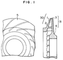
- Fig. 1 includes a front view and a side cross-sectional view showing a full-shroud vane wheel formed by the diffusion bonding according to the present invention.
- Fig. 2 includes schematic views showing a proceeding in a diffusion bonding method according to the present invention.
- Fig. 3 is a photograph showing a tempered martensite of a joint formed by the diffusion bonding according to the present invention.
- Fig. 4 is a diagram showing a relation between a charpy impact value of the joint and an insert member thickness.
- Fig. 5 is a photograph showing an undesirable phosphide formed by an insufficient mutual diffusion in the joint.
- Fig. 6 is a partially cross-sectional view showing a joint between parts of another full-shroud vane wheel formed by the diffusion bonding according to the present invention.
- Figs. 7a and 7b are schematic views showing respectively parts of another full-shroud vane wheel before the diffusion bonding according to the present invention.
- Fig. 8 is a partially cross-sectional view showing a joint between parts of another full-shroud vane wheel formed by the diffusion bonding according to the present invention.
- Fig. 9 is a diagram showing a relation between a remaining Ni content in the joint after the diffusion bonding and a charpy impact value of the joint.
- Figs. 1-5 show a first embodiment of a full-shroud vane wheel and a method for producing it, according to the present invention.
- the full-shroud vane wheel is made of 13 weight percent Cr steel.
- a first member 30 having a part 1 of each vane and a side plate 2 and a second member 31 having a part 3 of each vane and a core plate 4 are joined at front end surfaces 7 of the parts 1 and 2 by a diffusion bonding.
- the front end surfaces 7 of the parts 1 and 2 extend substantially perpendicularly to a rotational axis of the vane wheel.
- the vanes formed by combinations of the parts 1 and 2 extend substantially parallel to the rotational axis of the vane wheel.
- the first member 30 with the part 1 of each vane extending integrally from the side plate 2 and the second member 31 with the part 3 of each vane extending integrally from the core plate 4 are formed firstly.
- a roughness of the front end surfaces 7 is limited from 3 ⁇ m to 5 ⁇ m.
- a Ni-P (phosphorus content: 9-10 weight percent) layer 8 with a thickness of about 3 ⁇ m (actual thickness 2-5 ⁇ m) is formed on the front end surfaces 7 and surfaces of vanes extending continuously from the front end surfaces 7 by an electroless plating.
- Each of the front end surfaces 7 of the part 1 and each of the front end surfaces 7 of the part 3 are made contact each other to form the vane, and the combination of the first and second members 30 and 31 is received by an inside of a vacuum hot-press furnace 9. After the inside of the vacuum hot-press furnace 9 is vacuumed to 10 ⁇ 4 torr by a vacuum device 10, the combination of the first and second members 30 and 31 is heated to 1050°C by a heater 11.
- the combination of the first and second members 30 and 31 is compressed by a pressing device 12 to generate a compression surface stress of about 0.1 kg/mm2 on the front end surfaces 7, and these heating and compressing conditions are kept for 8 hours.
- the vacuum condition may be released after the diffusion bonding proceeds to such a degree that oxide is prevented from being generated on the front end surfaces 7.
- a melting temperature of the Ni-P layer 8 is 880°C, the Ni-P layer 8 is melted on the front end surfaces 7 by the heating so that a mutual diffusion between (Ni and P) of the Ni-P layer 8 and (Fe and Cr) of the parts 1 and 2 occurs. A part of the Ni-P layer 8 may flow out from the front end surfaces 7.
- micro-convex surfaces in the front end surfaces 7 are deformed or squashed plastically with discharging the Ni-P layer 8 from contact areas between the micro-convex surfaces so that a direct contact area between the parts 1 and 2 is increased. And, spaces formed by micro-concave surfaces in the front end surfaces 7 are filled by the Ni-P layer 8.
- the Ni-P layer 8 is substantially completely replaced by a joint layer 6 whose components and content ratios thereof are substantially equal to the components and content ratios of the parts 1 and 2, so that a martensite crystal structure of the joint layer 6 is substantially equal to that of the parts 1 and 2 after quenching and tempering the full-shroud vane wheel and a tensile strength (80 kg/mm2) and charpy impact value (10 kg ⁇ m/cm2 ) of the joint layer 6 are substantially equal to those of the parts 1 and 2.
- An axial length of the full-shroud vane wheel after the diffusion bonding is small by 2% in comparison with an axial length thereof before the diffusion bonding.
- the joint layer 6 includes a high-Ni-content layer after the diffusion bonding, the tensile strength of the joint layer 6 is substantially equal to that of the parts 1 and 2, but, the high charpy impact value of the joint layer 6 is not obtained. Therefore, it is important for obtaining the high charpy impact value of the joint layer 6 that the mutual diffusion is performed sufficiently.
- the thickness of the Ni-P layer 8 In order to perform sufficiently the mutual diffusion, it is important for the thickness of the Ni-P layer 8 to be close to the roughness of the front end surfaces 7. As shown in Fig. 4, when the thickness of the Ni-P layer 8 is 2-6 ⁇ m, the charpy impact value is not less than 10 kg ⁇ m/cm2. When the thickness of the Ni-P layer 8 is significantly smaller than the roughness of the front end surfaces 7, the melted Ni-P layer 8 cannot fill perfectly the voids on the front end surfaces 7 and the voids remain on the front end surfaces 7 so that the high charpy impact value of the joint layer 6 is not obtained.
- the mutual diffusion is not performed sufficiently in the whole of the Ni-P layer 8 so that a high-Ni-and-P-content layer remains in the joint layer 6 and a Fe-Ni-Cr phosphide is precipitated and formed therein as shown in Fig. 5.
- the Fe-Ni-Cr phosphide cannot be absorbed by the joint layer 6 with the heating, and the strength of the joint layer 6 is deteriorated by the Fe-Ni-Cr phosphide.
- the mutual diffusion between (Ni and P) of the Ni-P layer 8 and (Fe and Cr) of the parts 1 and 2 is performed sufficiently in the whole of the Ni-P layer 8 or the joint layer 6 and the high-Ni-and-P-content layer in the Ni-P layer 8 or the joint layer 6 disappears or diffuses into the parts 1 and 2 quickly before the Fe-Ni-Cr phosphide is generated so that the high charpy impact value of the joint layer 6 is obtained.
- the thickness of the Ni-P layer 8 is larger than 6 ⁇ m, (Ni and P) of the Ni-P layer 8 does not diffuse into the parts 1 and 2 quickly and substantially completely to remain in the joint layer 6, and the Fe-Ni-Cr phosphide is generated. Therefore, the high charpy impact value of the joint layer 6 is not obtained.
- An electrochemical plating may be used for forming the Ni-P layer 8 on the front end surfaces 7.
- the front end surfaces 7 may be coated with ultra fine grains of Ni-P alloy.
- the sub-micron diameter ultra fine powder of Ni-P alloy are mixed with an organic solvent, and a viscosity of the mixture determined by a mixing ratio between the ultra fine powder and the organic solvent is adjusted to obtain a constant desirable thickness of the mixture over the whole area of at least one of the front end surfaces 7 by a spinning coating.
- the organic solvent in the mixture vaporizes in the vacuum furnace 9 during the heating, so that the mutual diffusion bonding is not deteriorated by the organic solvent.
- the front end surface 7 of one of the parts 1 and 2 is coated with sub-micron diameter ultra fine grains of Ni and the front end surface 7 of another one of the parts 1 and 2 is coated with sub-micron diameter ultra fine grains of P.
- the front end surfaces 7 may be covered by a Ni-P alloy amorphous thin leaf.
- a heating temperature is limited below a maximum temperature for preventing an excessive crystal growth of at least one of the parts 1 and 2.
- the compression stress is limited below a maximum stress for preventing a buckling of at least one of the parts 1 and 2.
- the thickness of the Ni-P layer 8 is about 3 ⁇ m.
- the thickness of the Ni-P layer 8 is preferable for the thickness of the Ni-P layer 8 to be about 1-3 ⁇ m. But, it is of no practical use that the roughness of the front end surfaces 7 is less than 1 ⁇ m, or the thickness of the Ni-P layer 8 is about 1-2 ⁇ m.
- the charpy impact value of the joint layer 6 formed by the heating and compressing conditions (1050°C, 0.2 kg/mm2 compression surface stress, heating time of 8 hours), the thickness of the Ni-P layer 8 of about 3 ⁇ m, the roughness of the front end surfaces 7 of 10 ⁇ m and the Ni-P layer 8 of 9 weight percent P is 2 kg ⁇ m/cm2 with significantly large number of the voids in the joint layer 6.
- the charpy impact value of the joint layer 6 formed by the heating and compressing conditions (1050°C, 0.2 kg/mm2 compression surface stress heating time of 8 hours), the thickness of the Ni-P layer 8 of about 8 ⁇ m, the roughness of the front end surfaces 7 of 10 ⁇ m and the Ni-P layer 8 of 9 weight percent P is small with the phosphide and no voids in the joint layer 6.
- the charpy impact value of the joint layer 6 formed by the heating and compressing conditions (1050°C, 0.2 kg/mm2 compression surface stress, heating time of 20 hours), the thickness of the Ni-P layer 8 of about 8 ⁇ m, the roughness of the front end surfaces 7 of 10 ⁇ m and the Ni-P layer 8 of 4 weight percent P is not less than 10 kg ⁇ m/cm2 with no phosphide and no voids in the joint layer 6.
- a Ni-Si or Ni-B layer may be used.
- Fig. 6 shows a second embodiment of the full-shroud vane wheel according to the present invention.
- the full-shroud vane wheel is made of Cr-Mo steel (2.25 weight percent Cr, 1 weight percent Mo).
- the front end surfaces 7 of the parts 1 and 2 extend obliquely to the rotational axis of the vane wheel.
- the Ni-P (phosphorus content: 9-10 weight percent) layer 8 with the thickness of about 4 ⁇ m (actual thickness 2-5 ⁇ m) is formed on the whole of the vane wheel including a fluid path surface 13 in addition to the front end surfaces 7 and the surfaces of vanes extending continuously from the front end surfaces 7 by the electroless plating.
- Each of the front end surfaces 7 of the part 1 and each of the front end surfaces 7 of the part 3 are made contact each other to form the vane, and the combination of the first and second members 30 and 31 is received by the inside of a vacuum hot-press furnace 9.
- the combination of the first and second members 30 and 31 is heated to 1000°C by the heater 11.
- the combination of the first and second members 30 and 31 is compressed by the pressing device 12 to generate the compression surface stress of about 0.1 kg/mm2 on the front end surfaces 7, and these heating and compressing conditions are kept for 6 hours.
- the melting temperature of the Ni-P layer 8 is 880°C
- the Ni-P layer 8 is melted on the front end surfaces 7 by the heating of 1000°C so that the mutual diffusion between (Ni and P) of the Ni-P layer 8 and (Fe and Cr) of the parts 1 and 2 occurs without the voids and the phosphide.
- the oil quenching from 950°C
- tempering (680°C)
- the crystal structure of the whole of the full-shroud vane wheel including the joint layer 6 and the fluid path surface 13 is changed to the martensite crystal structure.
- the full-shroud vane wheel has a significantly high anti-corrosion characteristic against seawater in comparison with the quenched and tempered martensite of Cr-Mo steel, because the whole of surface of the full-shroud vane wheel according to the present invention is coated with the Ni-P layer, Ni and P of the Ni-P layer diffuse into the surface, and the crystal structure of the surface including the diffused Ni is quenched and tempered to be changed to the martensite crystal structure whose anti-corrosion characteristic improved by the diffused Ni.
- Ni content of the surface is slightly higher than that of the whole of the full-shroud vane wheel.
- a corrosion rate of the full-shroud vane wheel according to the present invention is one fifteenth of that of another full-shroud vane wheel which is made of 13 weight percent Cr cast steel and is not treated with the Ni-P layer, and a number of corrosion pits of the full-shroud vane wheel according to the present invention is significantly smaller than that of the another full-shroud vane wheel.
- a fatigue strength of the full-shroud vane wheel according to the present invention is 35 kg/mm2, and that of the another full-shroud vane wheel is 20 kg/mm2. Since an axial height of the part 1 is substantially equal to that of the part 3 in each vane, the strength of the joint layer 6 is not deteriorated by stress concentrations generated at junctions of the part 1 and the side plate 2 and of the part 3 and the core plate 4.
- Figs. 7a-7b and 8 show a third embodiment of the full-shroud vane wheel according to the present invention.
- the full-shroud vane wheel with an outer diameter of 400mm is made of 13 weight percent Cr steel.
- the first member 30 having the part 1 of each vane and the side plate 2 and the second member 31 having the part 3 of each vane and the core plate 4 are joined at the front end surfaces 7 by the diffusion bonding.
- the front end surfaces 7 of surface roughness 2-3 ⁇ m extend substantially perpendicularly to the rotational axis of the vane wheel and substantially parallel to pressed surfaces 14 on the side plate 2 and the core plate 4.
- the vanes formed by combinations of the parts 1 extend obliquely to the rotational axis of the vane wheel.
- the side plate 2 and the core plate 4 are positioned relatively to each other by inserting four pins 16 into respective pin holes 15 of the side plate 2 and the core plate 4, and subsequently joined by the diffusion bonding. Since the Ni-P layer 8 is arranged and melted on the front end surfaces 7, an excessive compression stress causing the buckling of the parts 1 and 3 or undesirable plastic deformation of the vane wheel is not necessary for the diffusion bonding.
Landscapes
- Engineering & Computer Science (AREA)
- Mechanical Engineering (AREA)
- General Engineering & Computer Science (AREA)
- Pressure Welding/Diffusion-Bonding (AREA)
- Structures Of Non-Positive Displacement Pumps (AREA)
- Heat Treatments In General, Especially Conveying And Cooling (AREA)
- Heat Treatment Of Articles (AREA)
Applications Claiming Priority (3)
| Application Number | Priority Date | Filing Date | Title |
|---|---|---|---|
| JP8248593 | 1993-03-18 | ||
| JP82485/93 | 1993-03-18 | ||
| JP08248593A JP3291827B2 (ja) | 1993-03-18 | 1993-03-18 | 羽根車及びディフューザ、並びにその製作方法 |
Publications (3)
| Publication Number | Publication Date |
|---|---|
| EP0615810A2 true EP0615810A2 (fr) | 1994-09-21 |
| EP0615810A3 EP0615810A3 (fr) | 1994-11-30 |
| EP0615810B1 EP0615810B1 (fr) | 2002-03-13 |
Family
ID=13775820
Family Applications (1)
| Application Number | Title | Priority Date | Filing Date |
|---|---|---|---|
| EP93119872A Expired - Lifetime EP0615810B1 (fr) | 1993-03-18 | 1993-12-09 | Partie d'aube et méthode pour former la jonction |
Country Status (4)
| Country | Link |
|---|---|
| US (1) | US5964398A (fr) |
| EP (1) | EP0615810B1 (fr) |
| JP (1) | JP3291827B2 (fr) |
| DE (1) | DE69331691T2 (fr) |
Cited By (3)
| Publication number | Priority date | Publication date | Assignee | Title |
|---|---|---|---|---|
| EP0890745A3 (fr) * | 1997-07-11 | 1999-02-03 | Hitachi, Ltd. | Soufflante entraínée par moteur et procédé de fabrication de la roue pour soufflante entrainée par moteur |
| WO2002027190A1 (fr) * | 2000-09-29 | 2002-04-04 | Pratt & Whitney Canada Corp. | Rouet multietage |
| EP3108991A1 (fr) * | 2015-06-22 | 2016-12-28 | Doosan Heavy Industries & Construction Co., Ltd. | Plaque d'échangeur de chaleur pour une transition de liaison en phase liquide |
Families Citing this family (23)
| Publication number | Priority date | Publication date | Assignee | Title |
|---|---|---|---|---|
| JPH11129078A (ja) * | 1997-08-29 | 1999-05-18 | Daido Steel Co Ltd | 二相ステンレス鋼の接合方法 |
| US6544662B2 (en) * | 1999-10-25 | 2003-04-08 | Alliedsignal Inc. | Process for manufacturing of brazed multi-channeled structures |
| JP2001200390A (ja) * | 1999-11-12 | 2001-07-24 | Osaka Gas Co Ltd | コンプレッサー用部材 |
| ITMI20021876A1 (it) * | 2002-09-03 | 2004-03-04 | Nuovo Pignone Spa | Procedimento migliorato per realizzare un rotore di un |
| DE102004024299A1 (de) | 2004-05-15 | 2005-12-01 | Alstom Technology Ltd | Geschweisstes Bauteil |
| JP4778735B2 (ja) * | 2005-06-24 | 2011-09-21 | 東芝機械株式会社 | ガラス成形用金型の製造方法 |
| DE102005032115A1 (de) * | 2005-07-07 | 2007-01-11 | Atotech Deutschland Gmbh | Verfahren zum Fügen von Werkstücken und mikrostrukturiertes Bauteil |
| JP4819570B2 (ja) * | 2006-02-10 | 2011-11-24 | アスモ株式会社 | クローズドインペラ及びそれを備えたウォータポンプ |
| DE502006002386D1 (de) * | 2006-08-17 | 2009-01-29 | Atotech Deutschland Gmbh | Verfahren zum Fügen von Werkstücken aus Edelstahl, Nickel oder Nickellegierungen unter Verwendung einer aus einer Nickel-Phosphorus-Legierung bestehenden Fügeschicht ; Verfahren zum Herstellen eines mikrostrukturierten Bauteils unter Verwendung eines solchen Verfahren |
| JP5019102B2 (ja) * | 2006-12-14 | 2012-09-05 | 東芝機械株式会社 | ガラス成形用金型の製造方法 |
| KR101053701B1 (ko) * | 2006-12-14 | 2011-08-02 | 도시바 기카이 가부시키가이샤 | 글래스 성형용 금형의 제조 방법 |
| JP4458109B2 (ja) | 2007-03-27 | 2010-04-28 | 株式会社日立プラントテクノロジー | 溶接溝封止構造 |
| DE112008000947B4 (de) * | 2007-04-10 | 2012-01-19 | Toshiba Kikai K.K. | Glasformgebungsform |
| WO2010090062A1 (fr) * | 2009-02-06 | 2010-08-12 | 三菱重工業株式会社 | Roue à aubes, compresseur et procédé de fabrication de roue à aubes |
| JP2010121612A (ja) * | 2008-10-23 | 2010-06-03 | Mitsubishi Heavy Ind Ltd | インペラ、圧縮機およびインペラの製造方法 |
| CN101554577B (zh) * | 2009-04-10 | 2011-05-11 | 南京工业大学 | 集成式不锈钢微流体反应器加工方法 |
| JP5422482B2 (ja) * | 2010-05-17 | 2014-02-19 | 三菱重工業株式会社 | インペラの製造方法 |
| JP5998544B2 (ja) * | 2012-03-13 | 2016-09-28 | アイシン精機株式会社 | インペラの製造方法およびインペラ |
| CN102817869A (zh) * | 2012-08-13 | 2012-12-12 | 势加透博(北京)科技有限公司 | 大型离心压缩机叶轮及其加工成形方法 |
| CN104279186A (zh) * | 2014-09-17 | 2015-01-14 | 杭州杭氧透平机械有限公司 | 一种大流量超大直径半铣半焊闭式三元叶轮及制造方法 |
| JP6982267B2 (ja) * | 2020-05-08 | 2021-12-17 | ダイキン工業株式会社 | クローズドインペラ及びクローズドインペラの製造方法 |
| RU2760352C1 (ru) * | 2021-03-18 | 2021-11-24 | Акционерное Общество "Наука И Инновации" | Способ формирования антикоррозионного покрытия на фасонной поверхности изделия из конструкционной стали перлитного класса |
| DE102023116229B4 (de) * | 2023-06-21 | 2026-02-26 | Ebm-Papst Mulfingen Gmbh & Co. Kg | Laufrad für Radiallüfter |
Family Cites Families (31)
| Publication number | Priority date | Publication date | Assignee | Title |
|---|---|---|---|---|
| FR1195124A (fr) * | 1957-04-26 | 1959-11-16 | Wiggin & Co Ltd Henry | Perfectionnements à la jonction des métaux |
| US3019512A (en) * | 1957-09-03 | 1962-02-06 | Edward A Stalker | Joint construction |
| JPS5411257B1 (fr) * | 1970-03-27 | 1979-05-14 | ||
| US3678570A (en) * | 1971-04-01 | 1972-07-25 | United Aircraft Corp | Diffusion bonding utilizing transient liquid phase |
| US3905723A (en) * | 1972-10-27 | 1975-09-16 | Norton Co | Composite ceramic turbine rotor |
| US3904101A (en) * | 1974-10-10 | 1975-09-09 | Gen Electric | Method of bonding a sheet cladding to a concave-convex substrate |
| FR2381591A1 (fr) * | 1977-02-24 | 1978-09-22 | Snecma | Procede de liaison par brasage-diffusion de pieces en acier ou superalliage |
| US4152816A (en) * | 1977-06-06 | 1979-05-08 | General Motors Corporation | Method of manufacturing a hybrid turbine rotor |
| JPS5464049A (en) * | 1977-10-31 | 1979-05-23 | Mitsubishi Electric Corp | Bonding of metals or alloys |
| JPS55107098A (en) * | 1979-02-07 | 1980-08-16 | Hitachi Ltd | Impeller for high efficiency compressor |
| JPS55125394A (en) * | 1979-03-23 | 1980-09-27 | Mitsubishi Heavy Ind Ltd | Control method of blade height dimension for diffusion welded impeller |
| JPS6036356B2 (ja) * | 1981-07-13 | 1985-08-20 | 株式会社日立製作所 | 拡散接合法 |
| JPS5893586A (ja) * | 1981-11-27 | 1983-06-03 | Hitachi Ltd | 耐熱合金の接合法 |
| DE3373792D1 (en) * | 1983-04-27 | 1987-10-29 | Bbc Brown Boveri & Cie | Method of joining metallic work pieces |
| DE3339751A1 (de) * | 1983-11-03 | 1985-05-15 | BBC Aktiengesellschaft Brown, Boveri & Cie., Baden, Aargau | Fuegeverfahren |
| DE3340031C2 (de) * | 1983-11-05 | 1985-11-21 | Thyssen Stahl AG, 4100 Duisburg | Panzerblech und Verfahren zu seiner Herstellung |
| JPS60131874A (ja) * | 1983-12-19 | 1985-07-13 | 三菱重工業株式会社 | セラミツクと金属との接合方法 |
| JPS60141867A (ja) * | 1983-12-28 | 1985-07-26 | Seiko Instr & Electronics Ltd | 金合金とステンレス鋼の接合方法 |
| JPH0613743B2 (ja) * | 1987-11-19 | 1994-02-23 | 工業技術院長 | ニッケル基超合金の固相接合法 |
| US4869421A (en) * | 1988-06-20 | 1989-09-26 | Rohr Industries, Inc. | Method of jointing titanium aluminide structures |
| US5251803A (en) * | 1988-07-22 | 1993-10-12 | Mitsubishi Denki Kabushiki Kaisha | Ceramic-metal composite substrate and method for producing the same |
| DE68924062T2 (de) * | 1988-12-10 | 1996-03-28 | Kawasaki Steel Co | Herstellungsverfahren von kristallinen gegenständen mit gerichteter kristallorientierung. |
| ATE167418T1 (de) * | 1989-03-28 | 1998-07-15 | Refurbished Turbine Components | Reparaturverfahren für turbinenschaufeln |
| US5305520A (en) * | 1990-09-01 | 1994-04-26 | Rolls-Royce Plc | Method of making fibre reinforced metal component |
| GB2247492B (en) * | 1990-09-01 | 1995-01-11 | Rolls Royce Plc | A method of making a fibre reinforced metal component |
| US5205822A (en) * | 1991-06-10 | 1993-04-27 | Cordis Corporation | Replaceable dilatation catheter |
| DE69302219T2 (de) * | 1992-06-05 | 1996-09-19 | Gec Alsthom Electromec | Verfahren zum Anbringen von Schutzüberzügen bildenden Einsätzen auf Gegenständen aus martensitischens Stahl oder aus Titanlegierungen |
| US5253797A (en) * | 1992-07-21 | 1993-10-19 | The United States Of America As Represented By The Secretary Of The Navy | Method of bonding molybdenum to steel |
| US5264011A (en) * | 1992-09-08 | 1993-11-23 | General Motors Corporation | Abrasive blade tips for cast single crystal gas turbine blades |
| US5454883A (en) * | 1993-02-02 | 1995-10-03 | Nippon Steel Corporation | High toughness low yield ratio, high fatigue strength steel plate and process of producing same |
| JP6235868B2 (ja) | 2013-10-31 | 2017-11-22 | 株式会社smart−FOA | 情報収集システム |
-
1993
- 1993-03-18 JP JP08248593A patent/JP3291827B2/ja not_active Expired - Fee Related
- 1993-12-09 DE DE69331691T patent/DE69331691T2/de not_active Expired - Lifetime
- 1993-12-09 EP EP93119872A patent/EP0615810B1/fr not_active Expired - Lifetime
-
1997
- 1997-09-15 US US08/929,089 patent/US5964398A/en not_active Expired - Lifetime
Cited By (4)
| Publication number | Priority date | Publication date | Assignee | Title |
|---|---|---|---|---|
| EP0890745A3 (fr) * | 1997-07-11 | 1999-02-03 | Hitachi, Ltd. | Soufflante entraínée par moteur et procédé de fabrication de la roue pour soufflante entrainée par moteur |
| WO2002027190A1 (fr) * | 2000-09-29 | 2002-04-04 | Pratt & Whitney Canada Corp. | Rouet multietage |
| US6499953B1 (en) | 2000-09-29 | 2002-12-31 | Pratt & Whitney Canada Corp. | Dual flow impeller |
| EP3108991A1 (fr) * | 2015-06-22 | 2016-12-28 | Doosan Heavy Industries & Construction Co., Ltd. | Plaque d'échangeur de chaleur pour une transition de liaison en phase liquide |
Also Published As
| Publication number | Publication date |
|---|---|
| EP0615810B1 (fr) | 2002-03-13 |
| DE69331691D1 (de) | 2002-04-18 |
| US5964398A (en) | 1999-10-12 |
| JP3291827B2 (ja) | 2002-06-17 |
| JPH06272696A (ja) | 1994-09-27 |
| DE69331691T2 (de) | 2002-10-31 |
| EP0615810A3 (fr) | 1994-11-30 |
Similar Documents
| Publication | Publication Date | Title |
|---|---|---|
| EP0615810A2 (fr) | Partie d'aube et méthode pour former la jonction | |
| EP1273672A1 (fr) | Un article d'acier soumis à des pression de surface élevée et methode de production pour ledit article | |
| JP2796551B2 (ja) | 厚肉細径燃料噴射管及びその製造方法 | |
| JPH0377775A (ja) | 高圧流体供給管の製造方法 | |
| US6488736B2 (en) | Method of producing sintered metal sprocket and sprocket produced by the method | |
| EP1847631A1 (fr) | Composant cémenté et son procédé de fabrication | |
| EP0722796B1 (fr) | Procédé pour la production des pièces frittées à base de fer traitées thermiquement | |
| TW499375B (en) | Sintered sprocket wheel | |
| JP2000073140A (ja) | 鉄道車両用車軸 | |
| JP3736838B2 (ja) | メカニカルヒューズおよびその製造方法 | |
| EP1199495B1 (fr) | Transmission toroidale à variation continue et procédé de production la transmission toroidale à variation continue | |
| US5145105A (en) | Diffusion bonding process | |
| US6488788B2 (en) | Flat plate member with a gear portion and a process for making the same | |
| EP0735150B1 (fr) | Procédé de fabrication d'une roue dentée en fonte | |
| JP4789141B2 (ja) | 鉄系部品の製造方法 | |
| JP4198268B2 (ja) | 鉄合金部品 | |
| JP2000039079A (ja) | アルミニウム合金製オートマチックトランスミッション用スプール弁 | |
| EP1098012B1 (fr) | Pieces en acier non traite thermiquement et nitruré doucement | |
| JP4116383B2 (ja) | 弁ばね用またはばね用のオイルテンパー線とその製造方法 | |
| JP2003277882A (ja) | 鉄合金部品およびその製造方法 | |
| JP4885062B2 (ja) | 拡散接合部材及びその製造方法 | |
| US20010012490A1 (en) | Sintered alloy and method for the hardening treatment thereof | |
| JPH05148598A (ja) | チタン又はチタン合金からなる基材の表面硬化法および表面硬化部材 | |
| EP4471282A1 (fr) | Vilebrequin et procédé de fabrication associé | |
| JP2021171774A (ja) | 接合部材、接合継手、接合継手の製造方法、及び接合部材の製造方法 |
Legal Events
| Date | Code | Title | Description |
|---|---|---|---|
| PUAI | Public reference made under article 153(3) epc to a published international application that has entered the european phase |
Free format text: ORIGINAL CODE: 0009012 |
|
| 17P | Request for examination filed |
Effective date: 19931209 |
|
| AK | Designated contracting states |
Kind code of ref document: A2 Designated state(s): DE FR GB |
|
| PUAL | Search report despatched |
Free format text: ORIGINAL CODE: 0009013 |
|
| AK | Designated contracting states |
Kind code of ref document: A3 Designated state(s): DE FR GB |
|
| 17Q | First examination report despatched |
Effective date: 19980416 |
|
| GRAG | Despatch of communication of intention to grant |
Free format text: ORIGINAL CODE: EPIDOS AGRA |
|
| GRAG | Despatch of communication of intention to grant |
Free format text: ORIGINAL CODE: EPIDOS AGRA |
|
| GRAH | Despatch of communication of intention to grant a patent |
Free format text: ORIGINAL CODE: EPIDOS IGRA |
|
| GRAH | Despatch of communication of intention to grant a patent |
Free format text: ORIGINAL CODE: EPIDOS IGRA |
|
| REG | Reference to a national code |
Ref country code: GB Ref legal event code: IF02 |
|
| GRAA | (expected) grant |
Free format text: ORIGINAL CODE: 0009210 |
|
| AK | Designated contracting states |
Kind code of ref document: B1 Designated state(s): DE FR GB |
|
| REF | Corresponds to: |
Ref document number: 69331691 Country of ref document: DE Date of ref document: 20020418 |
|
| ET | Fr: translation filed | ||
| PLBE | No opposition filed within time limit |
Free format text: ORIGINAL CODE: 0009261 |
|
| STAA | Information on the status of an ep patent application or granted ep patent |
Free format text: STATUS: NO OPPOSITION FILED WITHIN TIME LIMIT |
|
| 26N | No opposition filed |
Effective date: 20021216 |
|
| REG | Reference to a national code |
Ref country code: GB Ref legal event code: 732E |
|
| REG | Reference to a national code |
Ref country code: FR Ref legal event code: TP |
|
| PGFP | Annual fee paid to national office [announced via postgrant information from national office to epo] |
Ref country code: GB Payment date: 20091221 Year of fee payment: 17 Ref country code: FR Payment date: 20091203 Year of fee payment: 17 |
|
| PGFP | Annual fee paid to national office [announced via postgrant information from national office to epo] |
Ref country code: DE Payment date: 20091123 Year of fee payment: 17 |
|
| GBPC | Gb: european patent ceased through non-payment of renewal fee |
Effective date: 20101209 |
|
| REG | Reference to a national code |
Ref country code: FR Ref legal event code: ST Effective date: 20110831 |
|
| PG25 | Lapsed in a contracting state [announced via postgrant information from national office to epo] |
Ref country code: FR Free format text: LAPSE BECAUSE OF NON-PAYMENT OF DUE FEES Effective date: 20110103 |
|
| PG25 | Lapsed in a contracting state [announced via postgrant information from national office to epo] |
Ref country code: GB Free format text: LAPSE BECAUSE OF NON-PAYMENT OF DUE FEES Effective date: 20101209 Ref country code: DE Free format text: LAPSE BECAUSE OF NON-PAYMENT OF DUE FEES Effective date: 20110701 |
|
| REG | Reference to a national code |
Ref country code: DE Ref legal event code: R119 Ref document number: 69331691 Country of ref document: DE Effective date: 20110701 |