EP0616062A1 - Réparation de fil de trame cassé sur métiers à tisser à projectiles - Google Patents
Réparation de fil de trame cassé sur métiers à tisser à projectiles Download PDFInfo
- Publication number
- EP0616062A1 EP0616062A1 EP93810191A EP93810191A EP0616062A1 EP 0616062 A1 EP0616062 A1 EP 0616062A1 EP 93810191 A EP93810191 A EP 93810191A EP 93810191 A EP93810191 A EP 93810191A EP 0616062 A1 EP0616062 A1 EP 0616062A1
- Authority
- EP
- European Patent Office
- Prior art keywords
- weft
- weaving machine
- loom
- main shaft
- coupling part
- Prior art date
- Legal status (The legal status is an assumption and is not a legal conclusion. Google has not performed a legal analysis and makes no representation as to the accuracy of the status listed.)
- Withdrawn
Links
- 238000000034 method Methods 0.000 claims abstract description 22
- 230000008878 coupling Effects 0.000 claims abstract description 15
- 238000010168 coupling process Methods 0.000 claims abstract description 15
- 238000005859 coupling reaction Methods 0.000 claims abstract description 15
- 230000007246 mechanism Effects 0.000 claims abstract description 13
- 230000008569 process Effects 0.000 claims abstract description 9
- 238000009941 weaving Methods 0.000 claims description 28
- 238000004804 winding Methods 0.000 claims description 3
- 230000007547 defect Effects 0.000 claims 2
- 235000014676 Phragmites communis Nutrition 0.000 claims 1
- 238000001514 detection method Methods 0.000 claims 1
- 210000000056 organ Anatomy 0.000 claims 1
- 238000003780 insertion Methods 0.000 abstract description 2
- 230000037431 insertion Effects 0.000 abstract description 2
- 230000008859 change Effects 0.000 description 1
- 238000000926 separation method Methods 0.000 description 1
Images
Classifications
-
- D—TEXTILES; PAPER
- D03—WEAVING
- D03D—WOVEN FABRICS; METHODS OF WEAVING; LOOMS
- D03D51/00—Driving, starting, or stopping arrangements; Automatic stop motions
- D03D51/06—Driving, starting, or stopping arrangements; Automatic stop motions using particular methods of stopping
- D03D51/08—Driving, starting, or stopping arrangements; Automatic stop motions using particular methods of stopping stopping at definite point in weaving cycle, or moving to such point after stopping
- D03D51/085—Extraction of defective weft
-
- D—TEXTILES; PAPER
- D03—WEAVING
- D03D—WOVEN FABRICS; METHODS OF WEAVING; LOOMS
- D03D47/00—Looms in which bulk supply of weft does not pass through shed, e.g. shuttleless looms, gripper shuttle looms, dummy shuttle looms
- D03D47/12—Looms in which bulk supply of weft does not pass through shed, e.g. shuttleless looms, gripper shuttle looms, dummy shuttle looms wherein single picks of weft thread are inserted, i.e. with shedding between each pick
- D03D47/24—Looms in which bulk supply of weft does not pass through shed, e.g. shuttleless looms, gripper shuttle looms, dummy shuttle looms wherein single picks of weft thread are inserted, i.e. with shedding between each pick by gripper or dummy shuttle
Definitions
- the present invention relates to a method for automatically eliminating weft breaks according to the preamble of claim 1 and a projectile weaving machine for carrying out the method.
- the weaving machine comes to a standstill with a delay. This delay can lead to subsequent functions of the weaving machine being initiated which cannot be undone without the modules performing the functions being damaged. For this reason, the projectile weaving machine is equipped with an anti-reverse mechanism.
- the invention will remedy this.
- the invention as characterized in the claims, solves the problem of creating a method and a device for the automatic correction of shot errors, in which only a shot search process is required to eliminate a substantial proportion of the types of shot errors that usually occur.
- the working cycle of a weaving machine and thus that of the weft mechanism, the catching mechanism and the projectile return transport are known to be defined by the angular position of the main shaft.
- weft errors can occur during a weaving cycle, which can occur between the thread store and the pocket entrance and during the thread weft process.
- the method in question is intended in particular to correct weft breakage that occurs towards the end of the weft process. If such a weft break occurs, due to the delay occurring until the main shaft comes to a standstill, at least one of the functions initiated with the weft insertion process, e.g. a projectile has already been ejected from the trap. In order to remedy the weft break, the loom is turned in the opposite direction, namely to an angle of rotation position, which enables the weft break to be remedied automatically.
- the position is selected in which the threading of a new weft thread can be carried out.
- the threading channels and the corresponding thread tensioner are always in a defined position.
- the actual process of eliminating the weft breakage can be carried out using the method and the device as described in EP-A-458 736 (T.825).
- an anti-reverse mechanism is deactivated after the machine has come to a standstill, which is described below.
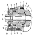
- the drive system of a projectile weaving machine essentially contains a drive device, a main shaft, a secondary shaft, a transverse shaft and a control shaft. At the weft end of the weaving machine, an anti-reverse mechanism is mounted at the end of the main shaft.
- a receiving part 3 On the End portion of the main shaft 1 is fixed by means of a nut 2, a receiving part 3 which rotates with the main shaft.
- the receiving part 3 is sleeve-shaped and has a flange 4.
- a liner 5 On the receiving part 3, a liner 5 is arranged, which is rotatably mounted on the circumference in a main shaft flange 6.
- the main shaft flange 6 is fastened to the machine frame 8 by means of screws 7.
- an annular part 9 is fastened in a recess by means of screws 10.
- the winding 11 of an electromagnet is arranged.
- a ring gear 12 with external teeth is arranged by means of screws 13.
- An armature part 15 is arranged between the ring-shaped part 9 and the ring gear 12 and is in operative connection with the winding 11.
- the anchor part 15 is guided and held on the screws 13.
- a first annular coupling part 16 is fastened to the circumference of the annular part 9, which is hereinafter referred to as the stationary coupling part, and a second annular coupling part 17 is fastened to the circumference of the anchor part 15, which is hereinafter referred to as the movable coupling part .
- the stationary and movable coupling part 16, 17 have sawtooth teeth on one end face and are arranged relative to one another in such a way that the teeth can be brought into and out of engagement.
- the movable coupling part 17 has an internal toothing 18 which is in engagement with the external toothing of the ring gear 12.
- the arrangement is housed in a housing 19 which is fastened to the main shaft flange 3 by means of screws 20. It is pointed out that the anti-reverse mechanism can be mounted at the end of the cross shaft.
- the electromagnet When the loom is switched on, the electromagnet is excited and the armature part 15 against the ring-shaped part 9 drawn. As a result, the stationary and the movable coupling part 16, 17 are brought into engagement. While the machine is starting up, the electromagnet is de-energized and the movable coupling part 17 is lifted off the stationary coupling part 16. If the weaving machine is switched off, the electromagnet is excited and the stationary and the movable coupling part 16, 17 are brought into engagement. If the weaving machine is switched off due to a weft break, the electromagnet is de-energized and the coupling parts 16, 17 disengaged after the weaving machine has come to a standstill. The weaving machine can thus be rotated in the opposite direction and returned to the rotational angle position defined for eliminating the weft break.
Landscapes
- Engineering & Computer Science (AREA)
- Textile Engineering (AREA)
- Looms (AREA)
Priority Applications (1)
| Application Number | Priority Date | Filing Date | Title |
|---|---|---|---|
| EP93810191A EP0616062A1 (fr) | 1993-03-17 | 1993-03-17 | Réparation de fil de trame cassé sur métiers à tisser à projectiles |
Applications Claiming Priority (1)
| Application Number | Priority Date | Filing Date | Title |
|---|---|---|---|
| EP93810191A EP0616062A1 (fr) | 1993-03-17 | 1993-03-17 | Réparation de fil de trame cassé sur métiers à tisser à projectiles |
Publications (1)
| Publication Number | Publication Date |
|---|---|
| EP0616062A1 true EP0616062A1 (fr) | 1994-09-21 |
Family
ID=8214932
Family Applications (1)
| Application Number | Title | Priority Date | Filing Date |
|---|---|---|---|
| EP93810191A Withdrawn EP0616062A1 (fr) | 1993-03-17 | 1993-03-17 | Réparation de fil de trame cassé sur métiers à tisser à projectiles |
Country Status (1)
| Country | Link |
|---|---|
| EP (1) | EP0616062A1 (fr) |
Citations (5)
| Publication number | Priority date | Publication date | Assignee | Title |
|---|---|---|---|---|
| NL7107996A (fr) * | 1971-06-10 | 1972-12-12 | ||
| EP0102515A2 (fr) * | 1982-08-05 | 1984-03-14 | Neue Baumwoll-Spinnerei und Weberei Hof AG | Machine à tisser à fausse navette avec un dispositif de recherche de la duite |
| EP0161012A1 (fr) * | 1984-04-06 | 1985-11-13 | Picanol N.V. | Mécanisme de recherche de la trame pour métiers à tisser |
| EP0354300A2 (fr) * | 1988-08-06 | 1990-02-14 | Nissan Texsys Co., Ltd. | Système et méthode pour le traitement de la trame dans un métier à jet de fluide |
| EP0458736A1 (fr) * | 1990-05-21 | 1991-11-27 | Gebrüder Sulzer Aktiengesellschaft | Extraction de fil de trame cassé sur métiers à tisser à projectiles |
-
1993
- 1993-03-17 EP EP93810191A patent/EP0616062A1/fr not_active Withdrawn
Patent Citations (5)
| Publication number | Priority date | Publication date | Assignee | Title |
|---|---|---|---|---|
| NL7107996A (fr) * | 1971-06-10 | 1972-12-12 | ||
| EP0102515A2 (fr) * | 1982-08-05 | 1984-03-14 | Neue Baumwoll-Spinnerei und Weberei Hof AG | Machine à tisser à fausse navette avec un dispositif de recherche de la duite |
| EP0161012A1 (fr) * | 1984-04-06 | 1985-11-13 | Picanol N.V. | Mécanisme de recherche de la trame pour métiers à tisser |
| EP0354300A2 (fr) * | 1988-08-06 | 1990-02-14 | Nissan Texsys Co., Ltd. | Système et méthode pour le traitement de la trame dans un métier à jet de fluide |
| EP0458736A1 (fr) * | 1990-05-21 | 1991-11-27 | Gebrüder Sulzer Aktiengesellschaft | Extraction de fil de trame cassé sur métiers à tisser à projectiles |
Similar Documents
| Publication | Publication Date | Title |
|---|---|---|
| DE4137681C2 (de) | Verfahren zur Verhinderung der Erzeugung eines Schußstreifens in einer Webmaschine | |
| EP0310804B1 (fr) | Dispositif pour éloigner un fil de trame cassé pour un métier à tisser à jet d'air | |
| DE4209686C2 (de) | Verfahren und Vorrichtung zur Herstellung von insbesondere knotenfreien Gewebe auf Luftdüsenwebmaschinen | |
| DE2836621C2 (de) | Luftversorgungssystem für eine pneumatische Webmaschine | |
| DE2854257C2 (de) | Textilmaschine | |
| EP0656437B1 (fr) | Procédé pour fournir et insérer du fil de trame dans le tissu d'un métier à tisser et fournisseur | |
| DE3537714A1 (de) | Verfahren zur handhabung eines schussfadens in einer schuetzenlosen webmaschine und vorrichtung zur durchfuehrung des verfahrens | |
| EP0648875B1 (fr) | Procédé pour éviter les bandes de tissage sur un métier à tisser | |
| DE69402356T2 (de) | Steuersystem für eine Vorrichtung zur Herstellung von Einlegekanten in Webmaschinen, insbesondere in Webmaschinen für durch Variation der Rietanschlagposition hergestellte Frottiergewebe | |
| DE2935507A1 (de) | Verfharen und einrichtung zum beheben eines schussfadenbruches | |
| EP1015370B1 (fr) | Procede pour le stockage intermediaire de fil, et appareil distributeur | |
| EP0616062A1 (fr) | Réparation de fil de trame cassé sur métiers à tisser à projectiles | |
| DE2226077A1 (de) | Verfahren und Vorrichtung zum Überwachen eines Auswechselns von Kopsen gegen Hülsen auf Spindeln an Ringspinn- und Ringzwirnmaschinen | |
| DE69203012T2 (de) | Vorrichtung für das Vermeiden von Schussbanden in eine Webmaschine. | |
| DE69112240T4 (de) | Vorrichtung zum automatischen Entweben an Webmaschinen mit mechanischem Schusseintrag. | |
| DE69905637T2 (de) | Verfahren zum Wiederstarten einer Webmaschine | |
| EP0565934A1 (fr) | Métier à tisser modulaire | |
| DE19521100C1 (de) | Kontrollierte Absaugung an Webmaschinen | |
| DE69210298T2 (de) | Vorrichtung für das Vermeiden von Schussbanden in einer Webmaschine | |
| DE3436165C2 (fr) | ||
| EP2403983A1 (fr) | Procédé pour faire fonctionner un métier à tisser pourvu d'une mécanique d'armure | |
| EP0458736A1 (fr) | Extraction de fil de trame cassé sur métiers à tisser à projectiles | |
| EP0567428B1 (fr) | Procédé pour démarrer un métier à tisser et métier à tisser pour effectuer ce procédé | |
| EP0629725A1 (fr) | Procédé pour démarrer un métier à tisser et métier à tisser pour effectuer ce procédé | |
| DE2441050A1 (de) | Webmaschine |
Legal Events
| Date | Code | Title | Description |
|---|---|---|---|
| PUAI | Public reference made under article 153(3) epc to a published international application that has entered the european phase |
Free format text: ORIGINAL CODE: 0009012 |
|
| AK | Designated contracting states |
Kind code of ref document: A1 Designated state(s): AT BE CH DE DK ES FR GB GR IE IT LI LU MC NL PT SE |
|
| RBV | Designated contracting states (corrected) |
Designated state(s): BE DE IT |
|
| STAA | Information on the status of an ep patent application or granted ep patent |
Free format text: STATUS: THE APPLICATION IS DEEMED TO BE WITHDRAWN |
|
| 18D | Application deemed to be withdrawn |
Effective date: 19950322 |