EP0616094A1 - Cassette de plafond - Google Patents
Cassette de plafond Download PDFInfo
- Publication number
- EP0616094A1 EP0616094A1 EP94102701A EP94102701A EP0616094A1 EP 0616094 A1 EP0616094 A1 EP 0616094A1 EP 94102701 A EP94102701 A EP 94102701A EP 94102701 A EP94102701 A EP 94102701A EP 0616094 A1 EP0616094 A1 EP 0616094A1
- Authority
- EP
- European Patent Office
- Prior art keywords
- cassette
- cassette according
- corner
- corner part
- edge
- Prior art date
- Legal status (The legal status is an assumption and is not a legal conclusion. Google has not performed a legal analysis and makes no representation as to the accuracy of the status listed.)
- Withdrawn
Links
- 238000004381 surface treatment Methods 0.000 claims description 2
- 239000000725 suspension Substances 0.000 abstract description 7
- 238000010276 construction Methods 0.000 abstract description 5
- 230000006978 adaptation Effects 0.000 abstract description 3
- 230000001747 exhibiting effect Effects 0.000 abstract 1
- 238000005452 bending Methods 0.000 description 2
- 238000003780 insertion Methods 0.000 description 2
- 230000037431 insertion Effects 0.000 description 2
- 238000004519 manufacturing process Methods 0.000 description 2
- 238000012986 modification Methods 0.000 description 2
- 230000004048 modification Effects 0.000 description 2
- 239000000843 powder Substances 0.000 description 2
- 230000002349 favourable effect Effects 0.000 description 1
- 238000009434 installation Methods 0.000 description 1
- 238000012423 maintenance Methods 0.000 description 1
- 239000002184 metal Substances 0.000 description 1
- 239000007769 metal material Substances 0.000 description 1
- 210000002105 tongue Anatomy 0.000 description 1
- 238000009423 ventilation Methods 0.000 description 1
Images
Classifications
-
- E—FIXED CONSTRUCTIONS
- E04—BUILDING
- E04B—GENERAL BUILDING CONSTRUCTIONS; WALLS, e.g. PARTITIONS; ROOFS; FLOORS; CEILINGS; INSULATION OR OTHER PROTECTION OF BUILDINGS
- E04B9/00—Ceilings; Construction of ceilings, e.g. false ceilings; Ceiling construction with regard to insulation
- E04B9/04—Ceilings; Construction of ceilings, e.g. false ceilings; Ceiling construction with regard to insulation comprising slabs, panels, sheets or the like
- E04B9/0478—Ceilings; Construction of ceilings, e.g. false ceilings; Ceiling construction with regard to insulation comprising slabs, panels, sheets or the like of the tray type
-
- E—FIXED CONSTRUCTIONS
- E04—BUILDING
- E04B—GENERAL BUILDING CONSTRUCTIONS; WALLS, e.g. PARTITIONS; ROOFS; FLOORS; CEILINGS; INSULATION OR OTHER PROTECTION OF BUILDINGS
- E04B9/00—Ceilings; Construction of ceilings, e.g. false ceilings; Ceiling construction with regard to insulation
- E04B9/003—Ceilings; Construction of ceilings, e.g. false ceilings; Ceiling construction with regard to insulation with movable parts, e.g. pivoting panels, access doors
Definitions
- the invention relates to a cassette for a ceiling, the cassette having a flat base body, on the longitudinal and transverse sides of which angled edge strips are formed, which are provided with means for suspending the cassette on a supporting structure.
- Cassettes for ceilings are known from the prior art in a wide variety of configurations.
- the cassettes are usually made of sheet metal, they can have a wide variety of sizes and can be provided with additional devices, for example lighting devices, ventilation devices or the like.
- the cassettes are designed in such a way that they can be attached to a supporting structure, usually in a detachable manner.
- the supporting structure is designed in the form of a grid suspended from a ceiling of a room or in a similar manner.
- Various constructions for the individual profiles that make up the supporting structure are known from the ceiling. Depending on these profiles and the type of attachment, it is necessary in the known solutions to manufacture the respective plate so that it fits the supporting structure.
- the invention has for its object to provide a cassette of the type mentioned, which is simple in construction and universally applicable and which can be manufactured easily and inexpensively.
- the object is achieved in that the corner regions of the edge strips of the cassette are each of identical design and that a separate corner part serving to suspend the cassette can be inserted into the respective corner of the cassette.
- the cassette according to the invention is characterized by a number of considerable advantages. Since the edge strips of the cassette, in particular in the corner area thereof, are of the same design, it is possible to fit a wide variety of supporting structures with a given embodiment of the cassette. It is only necessary to use appropriately shaped corner parts that are adapted to the supporting structure. Thus, according to the invention, there is no adaptation of the cassette itself, but only its corner part. From this in turn it follows that it is possible to use the same cassette for the most varied designs of supporting structures, it is only necessary to select the corner part accordingly.
- the corner parts according to the invention are retrofitted into the cassettes, the cassettes themselves can be surface-treated beforehand, for example painted or powder-coated. In contrast, the corner parts are for example only galvanized. This results in more favorable friction conditions when installing or removing the cassettes.
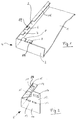
- FIG. 1 shows a perspective partial representation of an embodiment of a cassette according to the invention.
- This comprises a plate-shaped, flat base body 1, on the longitudinal sides of which edge strips 2 and on the transverse sides of which edge strips 3 are formed by angling.
- an additional stiffening strip 16 can be provided on the upper edge of the edge strip 2 (as well as on the edge strip 3) by bending the sheet metal material again, so that the cassette has a higher rigidity overall.
- tabs 6, 7 or 8, 9 are formed, which extend perpendicular to the edge strips 2, 3.
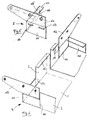
- Fig. 2 shows a perspective view of a corner part according to the invention.
- This comprises two legs 10, 11, which are formed in one piece with one another and arranged perpendicular to one another. This is used to attach and anchor the cassette to a support structure, not shown.
- Other configurations of the suspension area 12 are also possible; the prior art shows a wide variety of variants for this.
- the leg 11 is provided with two slots 13 which are arranged such that the tabs 8, 9 can be passed through the slots 13 (see FIG. 4).
- a stiffening edge 14 extending perpendicular to this is formed, which extends perpendicular to the leg 10. In the stiffening edge 14, two recesses 15 are punched out, which correspond in size to the tabs 6 and 7.
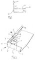
- Fig. 4 shows a partially assembled state of the corner part. This has been inserted into the corner of the cassette, the tabs 8, 9 being inserted through the slots 13 during insertion. The tabs 6 and 7 are inserted into the recesses 15. Thus, the corner part 5 is inserted into the corner area 4 of the cassette and aligned with it. The tongues 6 to 9 can now be deformed in the simplest way using pliers. As a result, the corner part 5 is fixed in position in the corner region 4 of the cassette. The corner part 5 is thus fixed in any direction on the cassette so that it can be hung or stored on the corner part 5.
- FIG. 4 shows a state in which the tabs 6 and 8 have already been deformed while the tabs 7 and 9 are still in the original orientation.
- a bending of individual tabs 6 to 9 can be avoided if at least one tab 6, 9 is provided with a slot 19 which runs parallel to the edge strip 2, 3.
- the corner part 5 then has a nose 20 in the area of these tabs, which snaps into the slot.
- 5 and 6 show a further embodiment of the corner part according to the invention.
- This is provided with a suspension area 12 which extends in the form of a longer leg and is provided with recesses.
- a suspension area 12 which extends in the form of a longer leg and is provided with recesses.
- the cassette can thus be folded down in the simplest way, for example to carry out maintenance work above the finished ceiling.
- 5 and 6 also show that the height of the edge strips 2, 3 and the size of the corner part can be varied and adapted to the respective requirements.
Landscapes
- Engineering & Computer Science (AREA)
- Architecture (AREA)
- Physics & Mathematics (AREA)
- Electromagnetism (AREA)
- Civil Engineering (AREA)
- Structural Engineering (AREA)
- Finishing Walls (AREA)
- Packaging Of Annular Or Rod-Shaped Articles, Wearing Apparel, Cassettes, Or The Like (AREA)
Applications Claiming Priority (2)
| Application Number | Priority Date | Filing Date | Title |
|---|---|---|---|
| DE4308615 | 1993-03-18 | ||
| DE19934308615 DE4308615A1 (de) | 1993-03-18 | 1993-03-18 | Kassette für eine Decke |
Publications (1)
| Publication Number | Publication Date |
|---|---|
| EP0616094A1 true EP0616094A1 (fr) | 1994-09-21 |
Family
ID=6483116
Family Applications (1)
| Application Number | Title | Priority Date | Filing Date |
|---|---|---|---|
| EP94102701A Withdrawn EP0616094A1 (fr) | 1993-03-18 | 1994-02-23 | Cassette de plafond |
Country Status (2)
| Country | Link |
|---|---|
| EP (1) | EP0616094A1 (fr) |
| DE (1) | DE4308615A1 (fr) |
Cited By (4)
| Publication number | Priority date | Publication date | Assignee | Title |
|---|---|---|---|---|
| NL1000356C2 (nl) * | 1995-05-12 | 1996-11-13 | Geel Syst Bv | Ophanginrichting voor plafondtegels. |
| FR2771117A1 (fr) * | 1997-11-17 | 1999-05-21 | Decoral | Panneau pose sur une structure en treillis pour constituer un plafond suspendu et plafond suspendu pourvu dudit panneau |
| EP0855477A3 (fr) * | 1997-01-22 | 1999-09-15 | Lindner Ag | Structure de plafond |
| CN107060180A (zh) * | 2017-04-27 | 2017-08-18 | 广州康普顿至高建材有限公司 | 一种挂板吊盒天花及其安装方法 |
Citations (4)
| Publication number | Priority date | Publication date | Assignee | Title |
|---|---|---|---|---|
| FR1270254A (fr) * | 1960-10-11 | 1961-08-25 | Barbier Et Cie G | Plafond métallique suspendu |
| NL6807147A (fr) * | 1968-05-21 | 1969-11-25 | ||
| NL7308827A (fr) * | 1972-06-28 | 1974-01-02 | ||
| FR2653537A1 (fr) * | 1989-10-20 | 1991-04-26 | Eswa Sa | Cassette de chauffage par rayonnement destinee a etre suspendue au plafond ou a la charpente d'un batiment. |
-
1993
- 1993-03-18 DE DE19934308615 patent/DE4308615A1/de not_active Withdrawn
-
1994
- 1994-02-23 EP EP94102701A patent/EP0616094A1/fr not_active Withdrawn
Patent Citations (4)
| Publication number | Priority date | Publication date | Assignee | Title |
|---|---|---|---|---|
| FR1270254A (fr) * | 1960-10-11 | 1961-08-25 | Barbier Et Cie G | Plafond métallique suspendu |
| NL6807147A (fr) * | 1968-05-21 | 1969-11-25 | ||
| NL7308827A (fr) * | 1972-06-28 | 1974-01-02 | ||
| FR2653537A1 (fr) * | 1989-10-20 | 1991-04-26 | Eswa Sa | Cassette de chauffage par rayonnement destinee a etre suspendue au plafond ou a la charpente d'un batiment. |
Cited By (5)
| Publication number | Priority date | Publication date | Assignee | Title |
|---|---|---|---|---|
| NL1000356C2 (nl) * | 1995-05-12 | 1996-11-13 | Geel Syst Bv | Ophanginrichting voor plafondtegels. |
| EP0744509A1 (fr) * | 1995-05-12 | 1996-11-27 | Van Geel Systems B.V. | Dispositif de suspension pour panneaux de faux plafonds |
| EP0855477A3 (fr) * | 1997-01-22 | 1999-09-15 | Lindner Ag | Structure de plafond |
| FR2771117A1 (fr) * | 1997-11-17 | 1999-05-21 | Decoral | Panneau pose sur une structure en treillis pour constituer un plafond suspendu et plafond suspendu pourvu dudit panneau |
| CN107060180A (zh) * | 2017-04-27 | 2017-08-18 | 广州康普顿至高建材有限公司 | 一种挂板吊盒天花及其安装方法 |
Also Published As
| Publication number | Publication date |
|---|---|
| DE4308615A1 (de) | 1994-09-22 |
Similar Documents
| Publication | Publication Date | Title |
|---|---|---|
| AT402594B (de) | Schubladenbausatz schubladenbausatz | |
| DE2232017A1 (de) | Rahmenkonstruktion zur halterung von plattenfoermigen teilen | |
| DE60221445T2 (de) | System für das abnehmbare aufhängen von regalen, schubladen o.ä. | |
| CH636394A5 (de) | Paneelkonstruktion. | |
| EP0283973A2 (fr) | Dispositif pour la fixation de boîtiers dans les ouvertures d'un tableau de commutation ou d'une paroi matricielle | |
| EP0217268A2 (fr) | Elément de plafond rectangulaire pour un faux plafond | |
| DE4308615A1 (de) | Kassette für eine Decke | |
| DE102005044322B4 (de) | Haltekonstruktion für Fassadenplatten, sowie Gebäudefassade | |
| EP0602334B1 (fr) | Construction de plafond suspendu | |
| DE4327411C2 (de) | Profilteil mit einer in Gleitnuten verschiebbar angeordneten Kralle | |
| DE3516013C2 (de) | Bauelementesatz für Raumdecken | |
| EP0118590A2 (fr) | Dispositif de suspension pour une poutre de plafond | |
| EP0465904B1 (fr) | Revêtement de plafond | |
| DE2049509C3 (de) | Halterung für Anschlußelementeträger | |
| DE4036493A1 (de) | Haltevorrichtung fuer informationstraeger | |
| AT401951B (de) | Montageschiene | |
| AT397125B (de) | Verschluss für öffnungen in raum- oder zwischendecken | |
| DE9000592U1 (de) | Tragkonstruktion für Deckenelemente | |
| DE2405388C3 (de) | Querprofilschelle für Unterdecken | |
| DE8518489U1 (de) | Unterkonstruktion für abhängende Unterdecken o.dgl. Verkleidungen | |
| EP0852836B1 (fr) | Element de liaison pour la fixation d'elements porteurs | |
| DE2259744A1 (de) | Haengedecke und verfahren zu deren anbringung | |
| DE19815665A1 (de) | Verbindungskralle zur Verbindung von Paneelelementen | |
| DE29706850U1 (de) | Präsentationssystem | |
| DE202004010968U1 (de) | Heizkessel |
Legal Events
| Date | Code | Title | Description |
|---|---|---|---|
| PUAI | Public reference made under article 153(3) epc to a published international application that has entered the european phase |
Free format text: ORIGINAL CODE: 0009012 |
|
| AK | Designated contracting states |
Kind code of ref document: A1 Designated state(s): AT BE CH GB LI NL |
|
| 17P | Request for examination filed |
Effective date: 19950317 |
|
| STAA | Information on the status of an ep patent application or granted ep patent |
Free format text: STATUS: THE APPLICATION IS DEEMED TO BE WITHDRAWN |
|
| 18D | Application deemed to be withdrawn |
Effective date: 19960903 |