EP0616128A1 - Dispositif de support pour un plateau en biais et procédé de fabrication - Google Patents
Dispositif de support pour un plateau en biais et procédé de fabrication Download PDFInfo
- Publication number
- EP0616128A1 EP0616128A1 EP94102157A EP94102157A EP0616128A1 EP 0616128 A1 EP0616128 A1 EP 0616128A1 EP 94102157 A EP94102157 A EP 94102157A EP 94102157 A EP94102157 A EP 94102157A EP 0616128 A1 EP0616128 A1 EP 0616128A1
- Authority
- EP
- European Patent Office
- Prior art keywords
- wobble plate
- rotation prevention
- prevention mechanism
- compressor
- ball
- Prior art date
- Legal status (The legal status is an assumption and is not a legal conclusion. Google has not performed a legal analysis and makes no representation as to the accuracy of the status listed.)
- Granted
Links
- 230000007246 mechanism Effects 0.000 title claims description 19
- 238000004519 manufacturing process Methods 0.000 title 1
- 238000007747 plating Methods 0.000 claims abstract description 33
- 229920001343 polytetrafluoroethylene Polymers 0.000 claims abstract description 19
- 239000004810 polytetrafluoroethylene Substances 0.000 claims abstract description 19
- 239000002131 composite material Substances 0.000 claims abstract description 15
- -1 polytetrafluoroethylene Polymers 0.000 claims abstract description 7
- 239000000463 material Substances 0.000 claims abstract description 5
- PXHVJJICTQNCMI-UHFFFAOYSA-N nickel Substances [Ni] PXHVJJICTQNCMI-UHFFFAOYSA-N 0.000 claims description 24
- 238000000034 method Methods 0.000 claims description 13
- 230000002265 prevention Effects 0.000 claims description 9
- 239000003507 refrigerant Substances 0.000 claims description 7
- 239000002904 solvent Substances 0.000 claims description 7
- 229910052759 nickel Inorganic materials 0.000 claims description 5
- OAICVXFJPJFONN-UHFFFAOYSA-N Phosphorus Chemical compound [P] OAICVXFJPJFONN-UHFFFAOYSA-N 0.000 claims description 4
- CDBYLPFSWZWCQE-UHFFFAOYSA-L Sodium Carbonate Chemical compound [Na+].[Na+].[O-]C([O-])=O CDBYLPFSWZWCQE-UHFFFAOYSA-L 0.000 claims description 4
- 229910000831 Steel Inorganic materials 0.000 claims description 4
- 239000011574 phosphorus Substances 0.000 claims description 4
- 229910052698 phosphorus Inorganic materials 0.000 claims description 4
- 239000010959 steel Substances 0.000 claims description 4
- 238000010438 heat treatment Methods 0.000 claims description 3
- 239000004094 surface-active agent Substances 0.000 claims description 3
- XFXPMWWXUTWYJX-UHFFFAOYSA-N Cyanide Chemical compound N#[C-] XFXPMWWXUTWYJX-UHFFFAOYSA-N 0.000 claims description 2
- 239000007864 aqueous solution Substances 0.000 claims description 2
- 239000001488 sodium phosphate Substances 0.000 claims description 2
- 229910000162 sodium phosphate Inorganic materials 0.000 claims description 2
- 239000000243 solution Substances 0.000 claims description 2
- RYFMWSXOAZQYPI-UHFFFAOYSA-K trisodium phosphate Chemical compound [Na+].[Na+].[Na+].[O-]P([O-])([O-])=O RYFMWSXOAZQYPI-UHFFFAOYSA-K 0.000 claims description 2
- UOCLXMDMGBRAIB-UHFFFAOYSA-N 1,1,1-trichloroethane Chemical compound CC(Cl)(Cl)Cl UOCLXMDMGBRAIB-UHFFFAOYSA-N 0.000 claims 1
- 238000001035 drying Methods 0.000 claims 1
- 238000007654 immersion Methods 0.000 claims 1
- 230000000573 anti-seizure effect Effects 0.000 abstract description 2
- 239000010687 lubricating oil Substances 0.000 description 4
- 238000007772 electroless plating Methods 0.000 description 3
- 239000002184 metal Substances 0.000 description 3
- 229910052751 metal Inorganic materials 0.000 description 3
- 239000004575 stone Substances 0.000 description 3
- VEXZGXHMUGYJMC-UHFFFAOYSA-N Hydrochloric acid Chemical compound Cl VEXZGXHMUGYJMC-UHFFFAOYSA-N 0.000 description 2
- 230000003247 decreasing effect Effects 0.000 description 2
- CWQXQMHSOZUFJS-UHFFFAOYSA-N molybdenum disulfide Chemical compound S=[Mo]=S CWQXQMHSOZUFJS-UHFFFAOYSA-N 0.000 description 2
- 229910052982 molybdenum disulfide Inorganic materials 0.000 description 2
- XLYOFNOQVPJJNP-UHFFFAOYSA-N water Substances O XLYOFNOQVPJJNP-UHFFFAOYSA-N 0.000 description 2
- BJEPYKJPYRNKOW-REOHCLBHSA-N (S)-malic acid Chemical compound OC(=O)[C@@H](O)CC(O)=O BJEPYKJPYRNKOW-REOHCLBHSA-N 0.000 description 1
- KWSLGOVYXMQPPX-UHFFFAOYSA-N 5-[3-(trifluoromethyl)phenyl]-2h-tetrazole Chemical compound FC(F)(F)C1=CC=CC(C2=NNN=N2)=C1 KWSLGOVYXMQPPX-UHFFFAOYSA-N 0.000 description 1
- 229910000760 Hardened steel Inorganic materials 0.000 description 1
- 229910021586 Nickel(II) chloride Inorganic materials 0.000 description 1
- 229920001800 Shellac Polymers 0.000 description 1
- 239000004115 Sodium Silicate Substances 0.000 description 1
- NRTOMJZYCJJWKI-UHFFFAOYSA-N Titanium nitride Chemical compound [Ti]#N NRTOMJZYCJJWKI-UHFFFAOYSA-N 0.000 description 1
- 239000002253 acid Substances 0.000 description 1
- BJEPYKJPYRNKOW-UHFFFAOYSA-N alpha-hydroxysuccinic acid Natural products OC(=O)C(O)CC(O)=O BJEPYKJPYRNKOW-UHFFFAOYSA-N 0.000 description 1
- 239000003638 chemical reducing agent Substances 0.000 description 1
- 239000004927 clay Substances 0.000 description 1
- 239000008139 complexing agent Substances 0.000 description 1
- 239000006185 dispersion Substances 0.000 description 1
- 229920001971 elastomer Polymers 0.000 description 1
- 239000012530 fluid Substances 0.000 description 1
- 239000011521 glass Substances 0.000 description 1
- 239000000314 lubricant Substances 0.000 description 1
- 238000005461 lubrication Methods 0.000 description 1
- 238000003754 machining Methods 0.000 description 1
- 239000001630 malic acid Substances 0.000 description 1
- 235000011090 malic acid Nutrition 0.000 description 1
- 239000003595 mist Substances 0.000 description 1
- 238000012986 modification Methods 0.000 description 1
- 230000004048 modification Effects 0.000 description 1
- QMMRZOWCJAIUJA-UHFFFAOYSA-L nickel dichloride Chemical compound Cl[Ni]Cl QMMRZOWCJAIUJA-UHFFFAOYSA-L 0.000 description 1
- 239000011347 resin Substances 0.000 description 1
- 229920005989 resin Polymers 0.000 description 1
- 239000005060 rubber Substances 0.000 description 1
- ZLGIYFNHBLSMPS-ATJNOEHPSA-N shellac Chemical compound OCCCCCC(O)C(O)CCCCCCCC(O)=O.C1C23[C@H](C(O)=O)CCC2[C@](C)(CO)[C@@H]1C(C(O)=O)=C[C@@H]3O ZLGIYFNHBLSMPS-ATJNOEHPSA-N 0.000 description 1
- 229940113147 shellac Drugs 0.000 description 1
- 235000013874 shellac Nutrition 0.000 description 1
- 239000004208 shellac Substances 0.000 description 1
- HBMJWWWQQXIZIP-UHFFFAOYSA-N silicon carbide Chemical compound [Si+]#[C-] HBMJWWWQQXIZIP-UHFFFAOYSA-N 0.000 description 1
- 229910001379 sodium hypophosphite Inorganic materials 0.000 description 1
- NTHWMYGWWRZVTN-UHFFFAOYSA-N sodium silicate Chemical compound [Na+].[Na+].[O-][Si]([O-])=O NTHWMYGWWRZVTN-UHFFFAOYSA-N 0.000 description 1
- 229910052911 sodium silicate Inorganic materials 0.000 description 1
- 239000002966 varnish Substances 0.000 description 1
Images

Classifications
-
- C—CHEMISTRY; METALLURGY
- C23—COATING METALLIC MATERIAL; COATING MATERIAL WITH METALLIC MATERIAL; CHEMICAL SURFACE TREATMENT; DIFFUSION TREATMENT OF METALLIC MATERIAL; COATING BY VACUUM EVAPORATION, BY SPUTTERING, BY ION IMPLANTATION OR BY CHEMICAL VAPOUR DEPOSITION, IN GENERAL; INHIBITING CORROSION OF METALLIC MATERIAL OR INCRUSTATION IN GENERAL
- C23C—COATING METALLIC MATERIAL; COATING MATERIAL WITH METALLIC MATERIAL; SURFACE TREATMENT OF METALLIC MATERIAL BY DIFFUSION INTO THE SURFACE, BY CHEMICAL CONVERSION OR SUBSTITUTION; COATING BY VACUUM EVAPORATION, BY SPUTTERING, BY ION IMPLANTATION OR BY CHEMICAL VAPOUR DEPOSITION, IN GENERAL
- C23C18/00—Chemical coating by decomposition of either liquid compounds or solutions of the coating forming compounds, without leaving reaction products of surface material in the coating; Contact plating
- C23C18/16—Chemical coating by decomposition of either liquid compounds or solutions of the coating forming compounds, without leaving reaction products of surface material in the coating; Contact plating by reduction or substitution, e.g. electroless plating
- C23C18/1601—Process or apparatus
- C23C18/1633—Process of electroless plating
- C23C18/1689—After-treatment
- C23C18/1692—Heat-treatment
- C23C18/1698—Control of temperature
-
- C—CHEMISTRY; METALLURGY
- C23—COATING METALLIC MATERIAL; COATING MATERIAL WITH METALLIC MATERIAL; CHEMICAL SURFACE TREATMENT; DIFFUSION TREATMENT OF METALLIC MATERIAL; COATING BY VACUUM EVAPORATION, BY SPUTTERING, BY ION IMPLANTATION OR BY CHEMICAL VAPOUR DEPOSITION, IN GENERAL; INHIBITING CORROSION OF METALLIC MATERIAL OR INCRUSTATION IN GENERAL
- C23C—COATING METALLIC MATERIAL; COATING MATERIAL WITH METALLIC MATERIAL; SURFACE TREATMENT OF METALLIC MATERIAL BY DIFFUSION INTO THE SURFACE, BY CHEMICAL CONVERSION OR SUBSTITUTION; COATING BY VACUUM EVAPORATION, BY SPUTTERING, BY ION IMPLANTATION OR BY CHEMICAL VAPOUR DEPOSITION, IN GENERAL
- C23C18/00—Chemical coating by decomposition of either liquid compounds or solutions of the coating forming compounds, without leaving reaction products of surface material in the coating; Contact plating
- C23C18/16—Chemical coating by decomposition of either liquid compounds or solutions of the coating forming compounds, without leaving reaction products of surface material in the coating; Contact plating by reduction or substitution, e.g. electroless plating
- C23C18/1601—Process or apparatus
- C23C18/1633—Process of electroless plating
- C23C18/1655—Process features
- C23C18/1662—Use of incorporated material in the solution or dispersion, e.g. particles, whiskers, wires
-
- C—CHEMISTRY; METALLURGY
- C23—COATING METALLIC MATERIAL; COATING MATERIAL WITH METALLIC MATERIAL; CHEMICAL SURFACE TREATMENT; DIFFUSION TREATMENT OF METALLIC MATERIAL; COATING BY VACUUM EVAPORATION, BY SPUTTERING, BY ION IMPLANTATION OR BY CHEMICAL VAPOUR DEPOSITION, IN GENERAL; INHIBITING CORROSION OF METALLIC MATERIAL OR INCRUSTATION IN GENERAL
- C23C—COATING METALLIC MATERIAL; COATING MATERIAL WITH METALLIC MATERIAL; SURFACE TREATMENT OF METALLIC MATERIAL BY DIFFUSION INTO THE SURFACE, BY CHEMICAL CONVERSION OR SUBSTITUTION; COATING BY VACUUM EVAPORATION, BY SPUTTERING, BY ION IMPLANTATION OR BY CHEMICAL VAPOUR DEPOSITION, IN GENERAL
- C23C18/00—Chemical coating by decomposition of either liquid compounds or solutions of the coating forming compounds, without leaving reaction products of surface material in the coating; Contact plating
- C23C18/16—Chemical coating by decomposition of either liquid compounds or solutions of the coating forming compounds, without leaving reaction products of surface material in the coating; Contact plating by reduction or substitution, e.g. electroless plating
- C23C18/31—Coating with metals
- C23C18/32—Coating with nickel, cobalt or mixtures thereof with phosphorus or boron
- C23C18/34—Coating with nickel, cobalt or mixtures thereof with phosphorus or boron using reducing agents
- C23C18/36—Coating with nickel, cobalt or mixtures thereof with phosphorus or boron using reducing agents using hypophosphites
-
- F—MECHANICAL ENGINEERING; LIGHTING; HEATING; WEAPONS; BLASTING
- F04—POSITIVE - DISPLACEMENT MACHINES FOR LIQUIDS; PUMPS FOR LIQUIDS OR ELASTIC FLUIDS
- F04B—POSITIVE-DISPLACEMENT MACHINES FOR LIQUIDS; PUMPS
- F04B27/00—Multi-cylinder pumps specially adapted for elastic fluids and characterised by number or arrangement of cylinders
- F04B27/08—Multi-cylinder pumps specially adapted for elastic fluids and characterised by number or arrangement of cylinders having cylinders coaxial with, or parallel or inclined to, main shaft axis
- F04B27/10—Multi-cylinder pumps specially adapted for elastic fluids and characterised by number or arrangement of cylinders having cylinders coaxial with, or parallel or inclined to, main shaft axis having stationary cylinders
- F04B27/1036—Component parts, details, e.g. sealings, lubrication
- F04B27/1054—Actuating elements
- F04B27/1063—Actuating-element bearing means or driving-axis bearing means
-
- F—MECHANICAL ENGINEERING; LIGHTING; HEATING; WEAPONS; BLASTING
- F05—INDEXING SCHEMES RELATING TO ENGINES OR PUMPS IN VARIOUS SUBCLASSES OF CLASSES F01-F04
- F05C—INDEXING SCHEME RELATING TO MATERIALS, MATERIAL PROPERTIES OR MATERIAL CHARACTERISTICS FOR MACHINES, ENGINES OR PUMPS OTHER THAN NON-POSITIVE-DISPLACEMENT MACHINES OR ENGINES
- F05C2201/00—Metals
- F05C2201/04—Heavy metals
- F05C2201/0433—Iron group; Ferrous alloys, e.g. steel
- F05C2201/0466—Nickel
-
- F—MECHANICAL ENGINEERING; LIGHTING; HEATING; WEAPONS; BLASTING
- F05—INDEXING SCHEMES RELATING TO ENGINES OR PUMPS IN VARIOUS SUBCLASSES OF CLASSES F01-F04
- F05C—INDEXING SCHEME RELATING TO MATERIALS, MATERIAL PROPERTIES OR MATERIAL CHARACTERISTICS FOR MACHINES, ENGINES OR PUMPS OTHER THAN NON-POSITIVE-DISPLACEMENT MACHINES OR ENGINES
- F05C2203/00—Non-metallic inorganic materials
- F05C2203/04—Phosphor
-
- F—MECHANICAL ENGINEERING; LIGHTING; HEATING; WEAPONS; BLASTING
- F05—INDEXING SCHEMES RELATING TO ENGINES OR PUMPS IN VARIOUS SUBCLASSES OF CLASSES F01-F04
- F05C—INDEXING SCHEME RELATING TO MATERIALS, MATERIAL PROPERTIES OR MATERIAL CHARACTERISTICS FOR MACHINES, ENGINES OR PUMPS OTHER THAN NON-POSITIVE-DISPLACEMENT MACHINES OR ENGINES
- F05C2203/00—Non-metallic inorganic materials
- F05C2203/08—Ceramics; Oxides
- F05C2203/0804—Non-oxide ceramics
- F05C2203/0813—Carbides
- F05C2203/0817—Carbides of silicon
-
- F—MECHANICAL ENGINEERING; LIGHTING; HEATING; WEAPONS; BLASTING
- F05—INDEXING SCHEMES RELATING TO ENGINES OR PUMPS IN VARIOUS SUBCLASSES OF CLASSES F01-F04
- F05C—INDEXING SCHEME RELATING TO MATERIALS, MATERIAL PROPERTIES OR MATERIAL CHARACTERISTICS FOR MACHINES, ENGINES OR PUMPS OTHER THAN NON-POSITIVE-DISPLACEMENT MACHINES OR ENGINES
- F05C2203/00—Non-metallic inorganic materials
- F05C2203/08—Ceramics; Oxides
- F05C2203/0804—Non-oxide ceramics
- F05C2203/083—Nitrides
- F05C2203/0847—Nitrides of titanium
-
- F—MECHANICAL ENGINEERING; LIGHTING; HEATING; WEAPONS; BLASTING
- F05—INDEXING SCHEMES RELATING TO ENGINES OR PUMPS IN VARIOUS SUBCLASSES OF CLASSES F01-F04
- F05C—INDEXING SCHEME RELATING TO MATERIALS, MATERIAL PROPERTIES OR MATERIAL CHARACTERISTICS FOR MACHINES, ENGINES OR PUMPS OTHER THAN NON-POSITIVE-DISPLACEMENT MACHINES OR ENGINES
- F05C2203/00—Non-metallic inorganic materials
- F05C2203/08—Ceramics; Oxides
- F05C2203/0804—Non-oxide ceramics
- F05C2203/0856—Sulfides
- F05C2203/086—Sulfides of molybdenum
-
- F—MECHANICAL ENGINEERING; LIGHTING; HEATING; WEAPONS; BLASTING
- F05—INDEXING SCHEMES RELATING TO ENGINES OR PUMPS IN VARIOUS SUBCLASSES OF CLASSES F01-F04
- F05C—INDEXING SCHEME RELATING TO MATERIALS, MATERIAL PROPERTIES OR MATERIAL CHARACTERISTICS FOR MACHINES, ENGINES OR PUMPS OTHER THAN NON-POSITIVE-DISPLACEMENT MACHINES OR ENGINES
- F05C2225/00—Synthetic polymers, e.g. plastics; Rubber
- F05C2225/04—PTFE [PolyTetraFluorEthylene]
-
- F—MECHANICAL ENGINEERING; LIGHTING; HEATING; WEAPONS; BLASTING
- F05—INDEXING SCHEMES RELATING TO ENGINES OR PUMPS IN VARIOUS SUBCLASSES OF CLASSES F01-F04
- F05C—INDEXING SCHEME RELATING TO MATERIALS, MATERIAL PROPERTIES OR MATERIAL CHARACTERISTICS FOR MACHINES, ENGINES OR PUMPS OTHER THAN NON-POSITIVE-DISPLACEMENT MACHINES OR ENGINES
- F05C2253/00—Other material characteristics; Treatment of material
- F05C2253/12—Coating
-
- Y—GENERAL TAGGING OF NEW TECHNOLOGICAL DEVELOPMENTS; GENERAL TAGGING OF CROSS-SECTIONAL TECHNOLOGIES SPANNING OVER SEVERAL SECTIONS OF THE IPC; TECHNICAL SUBJECTS COVERED BY FORMER USPC CROSS-REFERENCE ART COLLECTIONS [XRACs] AND DIGESTS
- Y10—TECHNICAL SUBJECTS COVERED BY FORMER USPC
- Y10T—TECHNICAL SUBJECTS COVERED BY FORMER US CLASSIFICATION
- Y10T74/00—Machine element or mechanism
- Y10T74/18—Mechanical movements
- Y10T74/18056—Rotary to or from reciprocating or oscillating
- Y10T74/18296—Cam and slide
- Y10T74/18336—Wabbler type
Definitions
- the present invention generally relates to a wobble plate type refrigerant compressor and, more particularly, to a thrust ball supporting mechanism for a wobble plate type compressor.
- a thrust support mechanism of the wobble plate type refrigerant compressor is well known.
- U.S. Patent No. 4,870,893 to Takahashi discloses a refrigerant compressor wherein the rotation of the compressor drive shaft is converted into reciprocating motion through a cam rotor.
- the cam rotor has a sloping end surface and is mounted on an end of the drive shaft.
- a wobble plate bears against the cam rotor through needle bearing, and is supported on a fixed member such as a cylinder block in such a manner that the wobble plate nutates, but does not rotate.
- the rotation of the cam rotor causes wobble plate to nutate, and the piston rods connected to the wobble plate are reciprocated to compress fluid within the cylinders.
- a bevel gear is fixed to the wobble plate at the outer thereof and another bevel gear is fixedly supported on the cylinder block.
- the bevel gears mesh so that the bevel gear on the wobble plate is prevented from rotating.
- Both of the bevel gears have ball seats at their center in which a bearing ball sits.
- the bearing ball and ball seats on the bevel gears are subjected to some of the largest axial loads in the compressor. Accordingly, proper lubrication of these parts is imperative. Under normal operating conditions, they are lubricated by a mist of lubricating oil generated by the moving parts the compressor. However, in the event that the compressor suffers a leakage of lubricating oil or continues to operate when the level of lubricating oil has decreased below a threshold level, the engaging surfaces may not be sufficiently lubricated, possibly resulting in abrading of the bearing ball or even failure of the compressor.
- prior art bevel gear rotation prevention mechanisms are substantially rigid bodies.
- the metal to metal contact of the bevel gears has been known to cause considerable and undesirable noise and vibration. This in turn can reduce the marketability and effective life of the compressor.
- the wobble plate type refrigerant compressor comprises a compressor housing having therein a cylinder block defined by a plurality of cylinders and a crank chamber adjacent the cylinders.
- a plurality of pistons are slidable fitted within each of the cylinders.
- a front end plate with a central opening is attached to one end surface of the compressor housing.
- a drive mechanism is coupled to the pistons to reciprocate the pistons within the cylinders.
- the drive mechanism includes a drive shaft extending through the central opening of the front end plate and rotatably supported by a radial bearing in the central opening.
- a wedge-shaped cam rotor having an annular outer end surface is operatively connected to the drive shaft.
- a wobble plate is disposed in proximity with the annular outer end surface and has a first bevel gear attached to a central portion thereof.
- the first bevel gear has a ball seat on an end face thereof.
- a second bevel gear is supported on the cylinder block and also has a ball seat on an end face thereof.
- the first and second bevel gears are opposed to one another but also axially aligned.
- a bearing ball is seated between the first and second bevel gears in the respective ball seats. The bearing ball supports the wobble plate as it nutates about the center of the ball.
- Either one or both of the first or second bevel gears is coated with an electroless composite plating layer having self-lubricative material dispersed therein.
- Figure 1 is a longitudinal cross-sectional view of a wobble plate refrigerant compressor in accordance with the preferred embodiment.
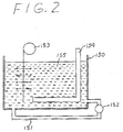
- Figure 2 is a schematic of the apparatus for plating the bevel gears of preferred embodiment.
- Compressor 1 includes a cylindrical compressor housing 2 with a front end plate 3 and a rear end plate 4 at opposite ends thereof.
- Rear end plate 4 is in the form of a cylindrical head.
- Cylinder block 21 is located within compressor housing 2 and crank chamber 22 is formed between interior surface of compressor housing 2, cylinder block 21 and the interior surface of front end plate 3.
- Valve plate 5 covers the combined exterior surfaces of compressor housing 2 and cylinder block 21, and cylinder head 4 is attached to compressor housing 2 via bolts 41 extending through valve plate 5.
- Front end plate 3 includes opening 31 through a central portion thereof and through which drive shaft 6 extends into crank chamber 22.
- Drive shaft 6 is rotably supported within opening 31 of front end plate 3 by radial needle bearing 7.
- Wedge-shaped cam rotor 8 is fixedly coupled to the end of drive shaft 6 within crank chamber 22.
- Cam rotor 8 is also supported on the interior surface of front end plate 3 by thrust needle bearing 9.
- Drive shaft 6 and cam rotor 8 rotate in unison.
- Wobble plate 10 is annular and is provided with first bevel gear 101 at its central portion. Wobble plate 10 engages inclined surface 81 of cam rotor 8 through thrust needle bearing 16.
- a supporting member 11 extends from cylinder block 21 to provide further support for wobble plate 10.
- Supporting member 11 includes shank portion 112 disposed within central bore 211 of cylindrical block 21, and second bevel gear 111 which engages first bevel gear 101 of wobble plate 10.
- Shank portion 112 includes hollow portion 113.
- Coil spring 13 is disposed within hollow portion 113 and urges supporting member 11 towards wobble plate 10.
- Adjusting screw 17 is disposed within central bore 211 adjacent the end of shank portion 112.
- a key (shown in phantom) is located between cylinder block 21 and supporting member 11 to prevent rotational motion of supporting member 11.
- Supporting member 11 nutatably supports wobble plate 10 with spherical element 12, (e.g., a steel ball) disposed between first bevel gear 101 and second bevel gear 111.
- spherical element 12 e.g., a steel ball
- a plurality of cylinders 212 are uniformly spaced around the periphery of cylinder block 21. Pistons 14 are slidably fitted within each cylinder 212. Connecting rods 15 connect each piston 14 to the periphery of wobble plate 10 via a ball joint.
- Discharge chamber 42 is centrally formed within cylinder head 4.
- Suction chamber 43 has an annular shape and is located within cylinder head 4 at the periphery thereof, around discharge chamber 42.
- Suction holes 51 are formed through valve plate 5 to link suction chamber 43 with each cylinder 212 and discharge holes 52 are also formed through valve plate 5 to link each cylinder 212 with discharge chamber 42 as well.
- a driving source rotates drive shaft 6 and cam rotor 8 via electromagnetic clutch 18 which is mounted on tubular extension 35 of front end plate 3.
- Wobble plate 10 nutates without rotating in accordance with the rotational movement of cam rotor 8, and each piston 14 reciprocates within cylinders 212.
- the recoil strength of spring 13 may be adjusted by rotating adjusting screw 17 to securely maintain the relative axial spacing between thrust bearing 9, cam rotor 8, wobble plate 10, first bevel gear 101, spherical element 12 and supporting member 11.
- the relative spacing may change when compressor 1 is operated due to dimensional error in the machining of the elements and due to changing temperature conditions within crank chamber 22.
- first bevel gear 101 of wobble plate 10 and second bevel gear 111 of supporting member 11 are made of a steel, e.g., a case hardened steel or a cemented steel.
- at least one of the bevel gears 101, 102 has an inner and an outer plating layer.
- the inner plating layer is preferably an electrical plating layer while the outer plating layer comprises an electroless composite plating layer, such as a Ni or Co electroless composite plating layer, containing a self-lubricative material, such as polytetrafluoroethylene (hereafter referred to as PTFE), silicon carbide (SiC), molybdenum disulfide (MoS2) or titanium nitride (TiN).
- PTFE polytetrafluoroethylene
- SiC silicon carbide
- MoS2 molybdenum disulfide
- TiN titanium nitride
- Outer electroless plating layers are preferred over outer electric plating layers because outer electroless plating layers have substantially uniform and accurate thicknesses. Accordingly, this plating method, e.g., PTFE-dispersed Ni electroless composite plating, is suitable for plating uneven portions of component parts.
- Plating bath 150 has a tube 151 extending between a bottom and a side wall thereof.
- a pump 152 positioned in tube 151 circulates the plating solvent within bath 150.
- Plating bath 150 has a jig 153 for fixing a part to be plated therein.
- Heater 154 is positioned within and heats plating bath 150.
- Plating bath is preferably filled with an electroless plating solvent 155.
- bevel gears 101, 102 are treated with a decreasing solvent such as thichloroethane. Then, bevel gears 101, 102 are treated with an electrical reducing solution comprising a sal soda, sodium phosphate, a cyanide soda and a surface active agent. Next, bevel gears 101,102 are rinsed with water and treated with an aqueous solution comprising 10% by weight hydrochloric acid. Finally, bevel gears 101, 102 are plated first electrically and second electrolessly. In the first plating step, a first ground coat of Ni is applied to bevel gears 101, 102 by electrical application. In the second plating step, a second ground coat of Ni is applied to bevel gears 101, 102 by electroless application. Accordingly, bevel gears 101, 102 have an outer layer comprising an Ni electroless composite plating layer containing PTFE.
- the resulting bevel gears 101, 102 with the foregoing composite plating layer are then (1) Immersed for about 2 hours in the following composite solvent bath maintained at about 85-90°C Operating Range Preferred Ni: Nickel chloride 3-7 g/l 5 g/l reducer: sodium hypophosphite 25-35 g/l 30 g/l complexing agent: acenttic acid or malic acid proper quantity lubricant: PTFE dispersion proper quantity other: surface active agent proper quantity (2) Rinsed in a cold water bath; (3) Dried; and (4) Heated at about 350°C for about 45 minutes Alternatively, the final heating step (4) may be omitted depending on whether the heating step is essential to properly coat the bevel gears.
- bevel gears 101, 102 have an outer plate between about 5-15 microns thick, and preferably 10 microns thick.
- the thickness of the plater layer is carefully controlled to be between the stated ranges. If the plate layer is not thick enough, the plated working surfaces of the bevel gears tend to varnish even under normal operating conditions. On the other hand, if the plate layer is too thick, the plated working surfaces of the bevel gears tend to peel under normal operating conditions.
- the plate layer preferably comprises 67 to 77% by weight nickel (Ni), preferably 72% by weight Ni; 6 to 10% by weight phosphorus (P), preferably 8% by weight P; and 17 to 23% by weight PTFE, preferably 20% by weight PTFE.
- JIS H8507 Japanese Industry Standard H8507 corresponding to ISO 2819
- Two tests in particular were selected from several adhesion tests specified in JIS H8507: (1) a gridability test and (2) a heat resistance test.
- the bevel gears 101, 102 were secured to a grinding machine having a grinding stone of #60 grains size or grit and an H-M grade.
- the grade of a grinding wheel or stone is a measure of the strength of its bond (e.g., resin, rubber, shellac, glass, clay, sodium silicate).
- the complete range of grades spans the letters A-Z, with A the softest and Z the hardest.
- the force that acts on the grain in grinding depends on process variables (such as speeds, depth of cut, etc.) and the strength of the work material. Thus, a greater force on the grain will increase the possibility of dislodging the grain; if the bond is too strong, the grain will tend to get dull, and if it is too weak then wheel wear will be great.
- the bevel gears 101, 102 were ground using a cutting speed between 10-33 m/s and an appropriate lubricating oil. If the plate layer is not sufficiently adhered to the metal of the bevel gears 101, 102, it should peel away under the influence of the grinding stone. This, however, did not occur in the plate layer according to the preferred embodiment.
- the bevel gears 101, 102 When at least one of the contacting surfaces of bevel gears 101, 102 are coated with the preferred Ni electroless composite plating layers having PTFE dispersed therein, the bevel gears 101, 102 exhibit low frictional resistance and high hardness.
- the preferred plating process improves anti-seizure and wear resistance properties of the compressor, which in turn enhances the performance of the compressor as well as reducing noise and prologing the effective life thereof.
Landscapes
- Chemical & Material Sciences (AREA)
- Engineering & Computer Science (AREA)
- Mechanical Engineering (AREA)
- General Chemical & Material Sciences (AREA)
- Chemical Kinetics & Catalysis (AREA)
- Materials Engineering (AREA)
- Metallurgy (AREA)
- Organic Chemistry (AREA)
- General Engineering & Computer Science (AREA)
- Dispersion Chemistry (AREA)
- Chemically Coating (AREA)
- Compressors, Vaccum Pumps And Other Relevant Systems (AREA)
Applications Claiming Priority (2)
| Application Number | Priority Date | Filing Date | Title |
|---|---|---|---|
| JP5025232A JPH06241161A (ja) | 1993-02-15 | 1993-02-15 | 圧縮機 |
| JP25232/93 | 1993-02-15 |
Publications (2)
| Publication Number | Publication Date |
|---|---|
| EP0616128A1 true EP0616128A1 (fr) | 1994-09-21 |
| EP0616128B1 EP0616128B1 (fr) | 1997-05-02 |
Family
ID=12160235
Family Applications (1)
| Application Number | Title | Priority Date | Filing Date |
|---|---|---|---|
| EP94102157A Expired - Lifetime EP0616128B1 (fr) | 1993-02-15 | 1994-02-11 | Dispositif de support pour un plateau en biais et procédé de fabrication |
Country Status (4)
| Country | Link |
|---|---|
| US (2) | US5415077A (fr) |
| EP (1) | EP0616128B1 (fr) |
| JP (1) | JPH06241161A (fr) |
| DE (1) | DE69402903T2 (fr) |
Cited By (3)
| Publication number | Priority date | Publication date | Assignee | Title |
|---|---|---|---|---|
| DE19612385A1 (de) * | 1995-03-30 | 1996-10-02 | Toyoda Automatic Loom Works | Verdrängungsvariabler Kompressor |
| DE19618524A1 (de) * | 1995-10-24 | 1997-04-30 | Mitsubishi Electric Corp | Axialkolbenpumpe vom Taumelscheibentyp |
| EP0852294A3 (fr) * | 1997-01-07 | 1999-06-09 | Zexel Corporation | Compresseur à plateau en biais à capacité variable et procédé de traitement de surface du plateau |
Families Citing this family (24)
| Publication number | Priority date | Publication date | Assignee | Title |
|---|---|---|---|---|
| US5553582A (en) * | 1995-01-04 | 1996-09-10 | Speas; Danny E. | Nutating disc engine |
| JPH09144652A (ja) * | 1995-11-24 | 1997-06-03 | Toyota Autom Loom Works Ltd | 可変容量圧縮機 |
| US5655432A (en) * | 1995-12-07 | 1997-08-12 | Ford Motor Company | Swash plate with polyfluoro elastomer coating |
| IT1278540B1 (it) * | 1995-12-20 | 1997-11-24 | Faip S R L Off Mec | Pompa per acqua ad alta pressione |
| IT1284106B1 (it) * | 1996-07-04 | 1998-05-08 | F A I P Srl Off Mec | Flangia multifunzione specie per macchine idropulitrici |
| JP3832012B2 (ja) * | 1997-03-31 | 2006-10-11 | 株式会社豊田自動織機 | 可変容量型圧縮機 |
| US5911809A (en) * | 1998-03-30 | 1999-06-15 | Ford Motor Company | Cobalt-tin alloy coating on aluminum by chemical conversion |
| JP2000018153A (ja) | 1998-06-30 | 2000-01-18 | Sanden Corp | 斜板式圧縮機 |
| JP2000088023A (ja) * | 1998-09-10 | 2000-03-28 | Toyota Autom Loom Works Ltd | バネ端の位置決め構造及びその位置決め構造を備えた圧縮機 |
| JP2001107843A (ja) * | 1999-10-12 | 2001-04-17 | Aida Eng Ltd | 可変ピストンポンプ・モータ |
| DE19954863A1 (de) * | 1999-11-15 | 2001-07-26 | Zexel Valeo Compressor Europe | Kolbenmaschine, insbesondere Verdichter |
| JP4869505B2 (ja) * | 2001-06-27 | 2012-02-08 | 株式会社ミツトヨ | エンコーダの摺動機構 |
| JP2003254232A (ja) * | 2002-03-04 | 2003-09-10 | Sanden Corp | 自動車空調用圧縮機及びそれに使用されるピストン |
| US7163754B2 (en) * | 2003-10-23 | 2007-01-16 | Deere & Company | Sprocket wheel having a metallurgically bonded coating and method for producing same |
| US6968751B2 (en) | 2004-01-21 | 2005-11-29 | Innovation Engineering, Inc. | Axial piston machines |
| RU2300015C2 (ru) * | 2005-03-05 | 2007-05-27 | Лев Анатольевич Кондаков | Аксиально-поршневая реверсивная объемно-роторная гидромашина |
| US7451687B2 (en) * | 2005-12-07 | 2008-11-18 | Thomas Industries, Inc. | Hybrid nutating pump |
| US7428812B2 (en) * | 2006-05-04 | 2008-09-30 | Fci Americas Technology, Inc. | Hydraulic tool with wobble plate transmission |
| US9003681B2 (en) * | 2006-09-18 | 2015-04-14 | Deere & Company | Bucket teeth having a metallurgically bonded coating and methods of making bucket teeth |
| US7487654B2 (en) | 2006-10-13 | 2009-02-10 | Fci Americas Technology, Inc. | Hydraulic tool with tactile feedback |
| US8122585B2 (en) * | 2007-02-20 | 2012-02-28 | Hubbell Incorporated | Spanner plate |
| WO2008116136A1 (fr) * | 2007-03-21 | 2008-09-25 | Gardner Denver Thomas, Inc. | Pompe de nutation hybride avec particularité antirotation |
| US10006449B2 (en) | 2015-01-14 | 2018-06-26 | Caterpillar Inc. | Bearing arrangement for cryogenic pump |
| DE102023136845A1 (de) * | 2023-12-29 | 2025-07-03 | Knorr-Bremse Systeme für Schienenfahrzeuge GmbH | Luftkompressor mit beschichtetem Zylinder |
Citations (7)
| Publication number | Priority date | Publication date | Assignee | Title |
|---|---|---|---|---|
| US4301716A (en) * | 1978-07-01 | 1981-11-24 | Sankyo Electric Company Limited | Refrigerant compressor units |
| WO1983002124A1 (fr) * | 1981-12-09 | 1983-06-23 | Robinson, W.W. | Procede permettant de deposer sur des articles metalliques et autres des revetements resistant a l'usure, et articles metalliques enrobes ameliores et autres |
| EP0250283A1 (fr) * | 1986-05-22 | 1987-12-23 | Alcatel Espace | Mécanisme d'entraînement du type "Harmonic Drive" pour utilisation dans le vide |
| US4870893A (en) * | 1987-01-10 | 1989-10-03 | Sanden Corporation | Wobble plate type compressor with a drive shaft attached to a cam rotor at an inclincation angle |
| EP0459740A1 (fr) * | 1990-05-31 | 1991-12-04 | Mono Pumps Limited | Pompe à vis excentrée |
| JPH04119249A (ja) * | 1990-09-04 | 1992-04-20 | Mitsubishi Materials Corp | 傘歯車および傘歯車装置 |
| JPH04346692A (ja) * | 1991-05-21 | 1992-12-02 | Seiko Epson Corp | 時計 |
Family Cites Families (8)
| Publication number | Priority date | Publication date | Assignee | Title |
|---|---|---|---|---|
| US3716348A (en) * | 1970-06-01 | 1973-02-13 | G Perkins | Method of forming abrasion-resistant self-lubricating coating on ferrous metals and aluminum and resulting articles |
| US4122215A (en) * | 1976-12-27 | 1978-10-24 | Bell Telephone Laboratories, Incorporated | Electroless deposition of nickel on a masked aluminum surface |
| US4621026A (en) * | 1981-12-09 | 1986-11-04 | Richmond Metal Finishers, Inc. | Process for providing metallic articles and the like with wear-resistant coatings, and improved coated metallic articles and the like |
| US4716059A (en) * | 1987-02-26 | 1987-12-29 | Allied Corporation | Composites of metal with carbon fluoride and method of preparation |
| US4830889A (en) * | 1987-09-21 | 1989-05-16 | Wear-Cote International, Inc. | Co-deposition of fluorinated carbon with electroless nickel |
| US4997686A (en) * | 1987-12-23 | 1991-03-05 | Surface Technology, Inc. | Composite electroless plating-solutions, processes, and articles thereof |
| JPH03242474A (ja) * | 1990-02-19 | 1991-10-29 | Sanden Corp | 斜板式圧縮機のプラネットプレート |
| US5232744A (en) * | 1991-02-21 | 1993-08-03 | C. Uyemura & Co., Ltd. | Electroless composite plating bath and method |
-
1993
- 1993-02-15 JP JP5025232A patent/JPH06241161A/ja active Pending
-
1994
- 1994-02-11 DE DE69402903T patent/DE69402903T2/de not_active Expired - Lifetime
- 1994-02-11 EP EP94102157A patent/EP0616128B1/fr not_active Expired - Lifetime
- 1994-02-14 US US08/195,195 patent/US5415077A/en not_active Expired - Fee Related
-
1996
- 1996-03-27 US US08/622,157 patent/US5789038A/en not_active Expired - Lifetime
Patent Citations (7)
| Publication number | Priority date | Publication date | Assignee | Title |
|---|---|---|---|---|
| US4301716A (en) * | 1978-07-01 | 1981-11-24 | Sankyo Electric Company Limited | Refrigerant compressor units |
| WO1983002124A1 (fr) * | 1981-12-09 | 1983-06-23 | Robinson, W.W. | Procede permettant de deposer sur des articles metalliques et autres des revetements resistant a l'usure, et articles metalliques enrobes ameliores et autres |
| EP0250283A1 (fr) * | 1986-05-22 | 1987-12-23 | Alcatel Espace | Mécanisme d'entraînement du type "Harmonic Drive" pour utilisation dans le vide |
| US4870893A (en) * | 1987-01-10 | 1989-10-03 | Sanden Corporation | Wobble plate type compressor with a drive shaft attached to a cam rotor at an inclincation angle |
| EP0459740A1 (fr) * | 1990-05-31 | 1991-12-04 | Mono Pumps Limited | Pompe à vis excentrée |
| JPH04119249A (ja) * | 1990-09-04 | 1992-04-20 | Mitsubishi Materials Corp | 傘歯車および傘歯車装置 |
| JPH04346692A (ja) * | 1991-05-21 | 1992-12-02 | Seiko Epson Corp | 時計 |
Non-Patent Citations (2)
| Title |
|---|
| DATABASE WPI Week 9303, Derwent World Patents Index; AN 93-021265 * |
| PATENT ABSTRACTS OF JAPAN vol. 16, no. 374 (M - 1293) 11 August 1992 (1992-08-11) * |
Cited By (7)
| Publication number | Priority date | Publication date | Assignee | Title |
|---|---|---|---|---|
| DE19612385A1 (de) * | 1995-03-30 | 1996-10-02 | Toyoda Automatic Loom Works | Verdrängungsvariabler Kompressor |
| US5741122A (en) * | 1995-03-30 | 1998-04-21 | Kabushiki Kaisha Toyoda Jidoshokki Seisakusho | Variable displacement compressor having a spool with a coating layer |
| DE19612385C2 (de) * | 1995-03-30 | 2001-01-25 | Toyoda Automatic Loom Works | Verdrängungsvariabler Kompressor |
| DE19618524A1 (de) * | 1995-10-24 | 1997-04-30 | Mitsubishi Electric Corp | Axialkolbenpumpe vom Taumelscheibentyp |
| US5809863A (en) * | 1995-10-24 | 1998-09-22 | Mitsubishi Denki Kabushiki Kaisha | Swash plate type axial piston pump |
| DE19618524B4 (de) * | 1995-10-24 | 2004-07-15 | Mitsubishi Denki K.K. | Axialkolbenpumpe vom Taumelscheibentyp |
| EP0852294A3 (fr) * | 1997-01-07 | 1999-06-09 | Zexel Corporation | Compresseur à plateau en biais à capacité variable et procédé de traitement de surface du plateau |
Also Published As
| Publication number | Publication date |
|---|---|
| DE69402903D1 (de) | 1997-06-05 |
| DE69402903T2 (de) | 1997-09-18 |
| US5415077A (en) | 1995-05-16 |
| US5789038A (en) | 1998-08-04 |
| JPH06241161A (ja) | 1994-08-30 |
| EP0616128B1 (fr) | 1997-05-02 |
Similar Documents
| Publication | Publication Date | Title |
|---|---|---|
| EP0616128B1 (fr) | Dispositif de support pour un plateau en biais et procédé de fabrication | |
| EP1548067B1 (fr) | Materiau glissant comprenant des particules plates de fluoropolymère et un liant | |
| EP1035326B1 (fr) | Revêtement de compresseur | |
| US6513238B1 (en) | Connecting rod with thermally sprayed bearing layer | |
| US5704272A (en) | Axial piston energy converting device | |
| US6329022B1 (en) | Connecting rod with a high strength bearing layer | |
| KR20020046211A (ko) | 압축기 및 압축기의 습동부품 | |
| EP1262661A1 (fr) | Patin pour un compresseur à plateau en biais et procédé de fabrication du patin | |
| US6367151B1 (en) | Connecting rod with thermally sprayed bearing layer | |
| EP1167761A2 (fr) | Compresseur à plateau en biais | |
| EP0943801A1 (fr) | Compresseur a plateau oscillant | |
| CN1213227C (zh) | 旋转斜盘型压缩机以及用于该压缩机的滑靴 | |
| EP1262662A1 (fr) | compresseur du type à plateau oscillant | |
| EP1134413A2 (fr) | Plateau en biais pour un compresseur | |
| US20030096134A1 (en) | Sliding member for compressor | |
| EP1256717A2 (fr) | Patin pour un compresseur à plateau en biais | |
| EP0852294A2 (fr) | Compresseur à plateau en biais à capacité variable et procédé de traitement de surface du plateau | |
| KR100327084B1 (ko) | 사판식 압축기 | |
| US20020119851A1 (en) | Pulley with microprofiled surface | |
| US6543333B2 (en) | Enriched cobalt-tin swashplate coating alloy | |
| EP1508693B1 (fr) | Revêtement de palier multicouches et sa méthode de fabrication | |
| EP2620676A2 (fr) | Améliorations de ou liées aux joints d'étanchéité | |
| KR20100138618A (ko) | 압축기 및 그 부품의 코팅방법 | |
| JPH022475B2 (fr) | ||
| EP2458212A2 (fr) | Compresseur à plateau oscillant et procédé de traitement en surface pour traiter la surface du plateau oscillant dans ce compresseur |
Legal Events
| Date | Code | Title | Description |
|---|---|---|---|
| PUAI | Public reference made under article 153(3) epc to a published international application that has entered the european phase |
Free format text: ORIGINAL CODE: 0009012 |
|
| AK | Designated contracting states |
Kind code of ref document: A1 Designated state(s): DE FR GB IT SE |
|
| 17P | Request for examination filed |
Effective date: 19940915 |
|
| 17Q | First examination report despatched |
Effective date: 19951116 |
|
| GRAG | Despatch of communication of intention to grant |
Free format text: ORIGINAL CODE: EPIDOS AGRA |
|
| GRAH | Despatch of communication of intention to grant a patent |
Free format text: ORIGINAL CODE: EPIDOS IGRA |
|
| GRAH | Despatch of communication of intention to grant a patent |
Free format text: ORIGINAL CODE: EPIDOS IGRA |
|
| GRAA | (expected) grant |
Free format text: ORIGINAL CODE: 0009210 |
|
| AK | Designated contracting states |
Kind code of ref document: B1 Designated state(s): DE FR GB IT SE |
|
| ITF | It: translation for a ep patent filed | ||
| REF | Corresponds to: |
Ref document number: 69402903 Country of ref document: DE Date of ref document: 19970605 |
|
| ET | Fr: translation filed | ||
| PLBE | No opposition filed within time limit |
Free format text: ORIGINAL CODE: 0009261 |
|
| STAA | Information on the status of an ep patent application or granted ep patent |
Free format text: STATUS: NO OPPOSITION FILED WITHIN TIME LIMIT |
|
| 26N | No opposition filed | ||
| REG | Reference to a national code |
Ref country code: GB Ref legal event code: IF02 |
|
| PGFP | Annual fee paid to national office [announced via postgrant information from national office to epo] |
Ref country code: GB Payment date: 20030205 Year of fee payment: 10 |
|
| PGFP | Annual fee paid to national office [announced via postgrant information from national office to epo] |
Ref country code: SE Payment date: 20040204 Year of fee payment: 11 |
|
| PG25 | Lapsed in a contracting state [announced via postgrant information from national office to epo] |
Ref country code: GB Free format text: LAPSE BECAUSE OF NON-PAYMENT OF DUE FEES Effective date: 20040211 |
|
| GBPC | Gb: european patent ceased through non-payment of renewal fee |
Effective date: 20040211 |
|
| PG25 | Lapsed in a contracting state [announced via postgrant information from national office to epo] |
Ref country code: IT Free format text: LAPSE BECAUSE OF NON-PAYMENT OF DUE FEES Effective date: 20050211 |
|
| PG25 | Lapsed in a contracting state [announced via postgrant information from national office to epo] |
Ref country code: SE Free format text: LAPSE BECAUSE OF NON-PAYMENT OF DUE FEES Effective date: 20050212 |
|
| EUG | Se: european patent has lapsed | ||
| PGFP | Annual fee paid to national office [announced via postgrant information from national office to epo] |
Ref country code: DE Payment date: 20110208 Year of fee payment: 18 Ref country code: FR Payment date: 20110218 Year of fee payment: 18 |
|
| REG | Reference to a national code |
Ref country code: FR Ref legal event code: ST Effective date: 20121031 |
|
| REG | Reference to a national code |
Ref country code: DE Ref legal event code: R119 Ref document number: 69402903 Country of ref document: DE Effective date: 20120901 |
|
| PG25 | Lapsed in a contracting state [announced via postgrant information from national office to epo] |
Ref country code: FR Free format text: LAPSE BECAUSE OF NON-PAYMENT OF DUE FEES Effective date: 20120229 |
|
| PG25 | Lapsed in a contracting state [announced via postgrant information from national office to epo] |
Ref country code: DE Free format text: LAPSE BECAUSE OF NON-PAYMENT OF DUE FEES Effective date: 20120901 |