EP0616129A1 - Contrôle du couple par l'angle de pivotement ou par l'excentricité d'une machine hydrostatique à pistons radiaux ou axiaux - Google Patents
Contrôle du couple par l'angle de pivotement ou par l'excentricité d'une machine hydrostatique à pistons radiaux ou axiaux Download PDFInfo
- Publication number
- EP0616129A1 EP0616129A1 EP94104021A EP94104021A EP0616129A1 EP 0616129 A1 EP0616129 A1 EP 0616129A1 EP 94104021 A EP94104021 A EP 94104021A EP 94104021 A EP94104021 A EP 94104021A EP 0616129 A1 EP0616129 A1 EP 0616129A1
- Authority
- EP
- European Patent Office
- Prior art keywords
- eccentricity
- torque
- swivel angle
- machine
- setpoint
- Prior art date
- Legal status (The legal status is an assumption and is not a legal conclusion. Google has not performed a legal analysis and makes no representation as to the accuracy of the status listed.)
- Withdrawn
Links
- 230000002706 hydrostatic effect Effects 0.000 title claims abstract description 19
- 238000006073 displacement reaction Methods 0.000 claims abstract description 12
- 238000005259 measurement Methods 0.000 claims description 6
- 230000007257 malfunction Effects 0.000 claims description 2
- 238000012360 testing method Methods 0.000 description 17
- 238000012937 correction Methods 0.000 description 14
- 238000002485 combustion reaction Methods 0.000 description 12
- 238000010586 diagram Methods 0.000 description 7
- 238000000034 method Methods 0.000 description 6
- 230000001419 dependent effect Effects 0.000 description 3
- 230000001105 regulatory effect Effects 0.000 description 3
- 230000001939 inductive effect Effects 0.000 description 2
- 230000001133 acceleration Effects 0.000 description 1
- 230000002411 adverse Effects 0.000 description 1
- 230000005540 biological transmission Effects 0.000 description 1
- 230000001276 controlling effect Effects 0.000 description 1
- 238000009795 derivation Methods 0.000 description 1
- 230000000694 effects Effects 0.000 description 1
- 238000012423 maintenance Methods 0.000 description 1
- 238000012545 processing Methods 0.000 description 1
- 230000006641 stabilisation Effects 0.000 description 1
- 238000011105 stabilization Methods 0.000 description 1
- 230000003068 static effect Effects 0.000 description 1
- 238000012546 transfer Methods 0.000 description 1
Images


Classifications
-
- F—MECHANICAL ENGINEERING; LIGHTING; HEATING; WEAPONS; BLASTING
- F16—ENGINEERING ELEMENTS AND UNITS; GENERAL MEASURES FOR PRODUCING AND MAINTAINING EFFECTIVE FUNCTIONING OF MACHINES OR INSTALLATIONS; THERMAL INSULATION IN GENERAL
- F16H—GEARING
- F16H61/00—Control functions within control units of change-speed- or reversing-gearings for conveying rotary motion ; Control of exclusively fluid gearing, friction gearing, gearings with endless flexible members or other particular types of gearing
- F16H61/38—Control of exclusively fluid gearing
- F16H61/40—Control of exclusively fluid gearing hydrostatic
- F16H61/4078—Fluid exchange between hydrostatic circuits and external sources or consumers
- F16H61/4096—Fluid exchange between hydrostatic circuits and external sources or consumers with pressure accumulators
-
- F—MECHANICAL ENGINEERING; LIGHTING; HEATING; WEAPONS; BLASTING
- F04—POSITIVE - DISPLACEMENT MACHINES FOR LIQUIDS; PUMPS FOR LIQUIDS OR ELASTIC FLUIDS
- F04B—POSITIVE-DISPLACEMENT MACHINES FOR LIQUIDS; PUMPS
- F04B1/00—Multi-cylinder machines or pumps characterised by number or arrangement of cylinders
- F04B1/04—Multi-cylinder machines or pumps characterised by number or arrangement of cylinders having cylinders in star- or fan-arrangement
- F04B1/06—Control
- F04B1/08—Control regulated by delivery pressure
-
- F—MECHANICAL ENGINEERING; LIGHTING; HEATING; WEAPONS; BLASTING
- F16—ENGINEERING ELEMENTS AND UNITS; GENERAL MEASURES FOR PRODUCING AND MAINTAINING EFFECTIVE FUNCTIONING OF MACHINES OR INSTALLATIONS; THERMAL INSULATION IN GENERAL
- F16H—GEARING
- F16H61/00—Control functions within control units of change-speed- or reversing-gearings for conveying rotary motion ; Control of exclusively fluid gearing, friction gearing, gearings with endless flexible members or other particular types of gearing
- F16H61/38—Control of exclusively fluid gearing
- F16H61/40—Control of exclusively fluid gearing hydrostatic
- F16H61/46—Automatic regulation in accordance with output requirements
-
- F—MECHANICAL ENGINEERING; LIGHTING; HEATING; WEAPONS; BLASTING
- F16—ENGINEERING ELEMENTS AND UNITS; GENERAL MEASURES FOR PRODUCING AND MAINTAINING EFFECTIVE FUNCTIONING OF MACHINES OR INSTALLATIONS; THERMAL INSULATION IN GENERAL
- F16H—GEARING
- F16H61/00—Control functions within control units of change-speed- or reversing-gearings for conveying rotary motion ; Control of exclusively fluid gearing, friction gearing, gearings with endless flexible members or other particular types of gearing
- F16H61/38—Control of exclusively fluid gearing
- F16H61/40—Control of exclusively fluid gearing hydrostatic
- F16H61/46—Automatic regulation in accordance with output requirements
- F16H61/472—Automatic regulation in accordance with output requirements for achieving a target output torque
-
- F—MECHANICAL ENGINEERING; LIGHTING; HEATING; WEAPONS; BLASTING
- F04—POSITIVE - DISPLACEMENT MACHINES FOR LIQUIDS; PUMPS FOR LIQUIDS OR ELASTIC FLUIDS
- F04B—POSITIVE-DISPLACEMENT MACHINES FOR LIQUIDS; PUMPS
- F04B2201/00—Pump parameters
- F04B2201/12—Parameters of driving or driven means
- F04B2201/1205—Position of a non-rotating inclined plate
- F04B2201/12051—Angular position
-
- F—MECHANICAL ENGINEERING; LIGHTING; HEATING; WEAPONS; BLASTING
- F04—POSITIVE - DISPLACEMENT MACHINES FOR LIQUIDS; PUMPS FOR LIQUIDS OR ELASTIC FLUIDS
- F04B—POSITIVE-DISPLACEMENT MACHINES FOR LIQUIDS; PUMPS
- F04B2205/00—Fluid parameters
- F04B2205/05—Pressure after the pump outlet
-
- F—MECHANICAL ENGINEERING; LIGHTING; HEATING; WEAPONS; BLASTING
- F04—POSITIVE - DISPLACEMENT MACHINES FOR LIQUIDS; PUMPS FOR LIQUIDS OR ELASTIC FLUIDS
- F04B—POSITIVE-DISPLACEMENT MACHINES FOR LIQUIDS; PUMPS
- F04B2207/00—External parameters
- F04B2207/04—Settings
- F04B2207/044—Settings of the rotational speed of the driving motor
- F04B2207/0441—Settings of the rotational speed of the driving motor maximum
-
- F—MECHANICAL ENGINEERING; LIGHTING; HEATING; WEAPONS; BLASTING
- F04—POSITIVE - DISPLACEMENT MACHINES FOR LIQUIDS; PUMPS FOR LIQUIDS OR ELASTIC FLUIDS
- F04B—POSITIVE-DISPLACEMENT MACHINES FOR LIQUIDS; PUMPS
- F04B2207/00—External parameters
- F04B2207/04—Settings
- F04B2207/044—Settings of the rotational speed of the driving motor
- F04B2207/0442—Settings of the rotational speed of the driving motor minimum
-
- F—MECHANICAL ENGINEERING; LIGHTING; HEATING; WEAPONS; BLASTING
- F16—ENGINEERING ELEMENTS AND UNITS; GENERAL MEASURES FOR PRODUCING AND MAINTAINING EFFECTIVE FUNCTIONING OF MACHINES OR INSTALLATIONS; THERMAL INSULATION IN GENERAL
- F16H—GEARING
- F16H59/00—Control inputs to control units of change-speed- or reversing-gearings for conveying rotary motion
- F16H59/68—Inputs being a function of gearing status
- F16H2059/6838—Sensing gearing status of hydrostatic transmissions
- F16H2059/6853—Sensing gearing status of hydrostatic transmissions the state of the transmission units, i.e. motor or pump capacity, e.g. for controlled shifting of range gear
Definitions
- the invention relates to a circuit arrangement for torque control of a hydrostatic machine unit.
- the invention relates to such an arrangement for use in a highly dynamic test bench for internal combustion engines.
- DE 28 48 595 A1 describes a method and a device for regulating the output torque of a transmission, in which two, a primary and a secondary hydrostatic are volume flow coupled.
- the use of this device requires an intervention on the primary-side hydrostat for the purpose of the ⁇ p change for the control of the torque. This means that the hydraulic spring formed by this device has an adverse effect on the dynamics of this device.
- the object of the present invention is to avoid the disadvantages of the prior art.
- the present invention intends to provide a method and a device for torque control of a hydrostatic machine unit, as can be used in particular in highly dynamic test benches for internal combustion engines.
- the invention is based on the finding that in order to avoid a measuring hub with a hydrostatic solution and a system with an impressed pressure, the torque would have to be determined in a different way.
- the torque is proportional to the pressure difference and the displacement of a hydrostatic machine unit, it is proposed to use the variables representing the displacement of the machine, such as the swivel angle or the eccentricity, in order to determine the torque.
- the speed can be easily, for example. be determined by a speedometer machine.
- control signal generating means which generates a control signal by which the stroke volume of the machine unit determining the torque of the hydrostatic machine unit, in particular below Taking into account the above operating parameters.
- This control signal is either calculated by the circuit in an analog solution or in a digital solution a memory such. B. taken from an EPROM where these measured values were previously saved after their practical determination.
- a torque limit value is preferably superimposed on the torque control, which cannot be exceeded if the machine malfunctions.
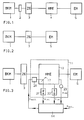
- Fig. 1 shows schematically and Fig. 1a in detail a test bench for internal combustion engines.
- an internal combustion engine 1 which is coupled via a torque measuring hub 2 to an intermediate gear 3, which in turn is coupled to a hydrostatic machine unit 4, which in turn is connected to an electrical machine 5.
- hydraulic storage means shown in FIG. 1 are not provided in FIG. 1, which supply the energy required for self-acceleration of the loading machine 2, 3, 4 and store it again during the braking process.
- FIG. 2 shows a block diagram for a purely electrical solution, in which an internal combustion engine 1 and an electric motor 5 and an intermediate gear 3 are again provided, similarly to FIG. 1, but no torque measuring hub is required here since the same is calculated.
- the disadvantages of such an arrangement have already been mentioned.
- Fig. 3 shows a block diagram of a first embodiment of the invention.
- the internal combustion engine is again designated 1, the intermediate gear 3 and the electric motor 5 similar to FIG. 1.
- a hydrostatic machine unit 10 consisting of at least two hydrostatic machines 10a, 10b lies between the intermediate gear 3 and the electric motor 5.
- the machine unit 10 can be designed similarly to that in FIG. 1a.
- the advantage of using a machine unit 10 with, for example. Two sets of pumps / motors as shown in Fig. 1a has the advantage of higher dynamics compared to a single machine twice as large.
- the engine unit 10 supplies its parameter or parameters, in particular ⁇ is n is p is (if necessary, also the temperature and other values) to control signal generating means (in short, a control circuit) 14.
- the control circuit 14 is a the target torque representing target torque signal M should fed. Based on the target torque signal and the parameters ⁇ ist , N ist , P ist and possibly other parameters, the control circuit 14 determines a control signal ⁇ soll . In the case of a corresponding pump, this signal ⁇ soll denotes the setpoint of the pivot angle. With another pump type, ⁇ setpoint would be the eccentricity setpoint. In general, ⁇ is supposed to represent this on the basis of the present Torque setpoint signal required stroke volume of the machine unit 10.
- the displacement volume changing means 17 are simply referred to here as swash plates, since this is a typical example of the displacement volume changing means as can be used in a hydrostatic machine unit.
- swash plates could also be provided, and other means that change the eccentricity of a pump could also be provided instead of the swash plates.
- the actual swivel angle value signal ⁇ ist is reported back by a displacement transducer 21 which is connected directly or indirectly to the swash plate 17 on the input side. Furthermore, a tachometer generator 22 is provided, which is connected, for example, to the shaft of the machine unit 10 and supplies the actual speed signal n ist to the control circuit 14. Furthermore, a pressure transducer 23 supplies an actual pressure value signal p ist to the control circuit 14, this actual pressure value indicating the impressed operating pressure of the machine unit 10. Overall, the machine unit 10 together with the actuator 20, displacement transducer 21, tachometer generator 22 and pressure cell 23 is referred to as a hydrostatic machine arrangement 11.
- FIG. 4 shows a second exemplary embodiment of the invention, which differs from that according to FIG. 3 in particular in that the processing of the swivel angle setpoint signal ⁇ is intended and the derivation of the swivel angle actual value signal is shown in more detail.
- the machine unit is again designated 10, but is only shown schematically, ie there are preferably other components such as accumulators as shown in Fig. 1a. It is important that, just as in the exemplary embodiment according to FIG. 3, a torque measuring hub can be dispensed with according to the invention, since the torque can be determined from existing values due to the use of the secondary control. As far as the term secondary control is concerned, reference should also be made to volume 6 of "The hydraulic trainer" mentioned at the outset, in particular pages 13 and following.
- the actuator 20 is designed as a hydraulic cylinder which serves to pivot the swash plate 17 in accordance with the swivel angle setpoint signal ⁇ Soll .
- the piston of the hydraulic cylinder 20 is further connected, of the swivel angle signal ⁇ to the Control circuit 14 provides. Compare also pictures 7 and 8 on pages 18 and 19 of volume 6 of "Der Hydrauliktrainer".
- Fig. 5 shows a block diagram of a third embodiment of the invention according to which the control circuit 14, first according to the geirrin torque setpoint signal M to n is in particular based on the actual speed and p to the actual pressure, a signal is generated which modifies in a correction circuit 31 or by a correction signal K is so as to generate the swivel angle setpoint signal ⁇ soll .
- FIG. 7 shows a fifth exemplary embodiment of the invention, here again a control circuit 14 is shown in detail.
- the control circuit 14 is implemented on cards, the torque card 35 in particular being described in more detail here.
- reference numerals 6c, 30c, 10c 8c of FIG. 7 and also of FIG. 4 are entered for illustration.
- the torque setpoint signal M soll is fed to a computing circuit 42 via a node 41.
- a link with actual speed values At the second input of the computing circuit 42 there is an actual pressure value signal p ist .
- the arithmetic circuit 42 determines a desired M to the corresponding ⁇ intended. This value is preferably fed to a connection point 43, where a connection with a correction variable is possibly made, which is applied via connection 24c. Then leaves the in the manner processed pivot angle setpoint signal ⁇ to at 2c, the torque map 35 and ⁇ in a PD controller 44 together with the Istwertwertsignal is processed at 40 than ⁇ the valve is to be supplied to the 25th
- An important feature of the control circuit according to FIG. 7 is the provision of a speed limitation.
- the desired threshold value for the rotational speed is then input to the torque map 35 at 28 and at 4c occurs to n a speed setpoint corresponding to the desired speed limit from.
- This value n should lie in the shown Via a connection point at an input of a PID controller 45, at the other input of which the actual speed value n is . If a fault is present, is made ineffective at the junction point 46 by the PID controller 45 to the signal ⁇ .
- the swivel angle actual value (6c -> 6a) is linked to the actual pressure value (10c -> 10a) and a correction value by an analog arithmetic circuit 50.
- the correction value is either formed by an analog arithmetic circuit on the base map depending on the nominal size of the selected secondary unit and the current speed, or by an additional digital correction value card depending on the speed, pressure and temperature depending on the preselected nominal size from a characteristic field.
- the correction value represents the swivel angle dependent on these quantities, which is additionally necessary in motor and generator operation in order to compensate for the losses in unit 10 and to keep the torque constant.
- this correction value is subtracted from the measured swivel angle and then the actually acting torque is calculated by multiplicative linking with the measured pressure value and output to a short-circuit proof amplifier at 4a.
- this correction value becomes the measured swivel angle added, since the correction value now acts in the sense of an additional torque.
- torque card 35 Another particularly preferred possibility of the torque card 35 is the electronic maintenance of a preselected torque by influencing the swivel angle setpoint, taking into account the system-dependent correction values.
- the correction value is generated as for torque determination.
- the correction value is added to the calculated target swivel angle, which results from the target torque and the actual pressure, and with the resulting analog voltage value via a limiter circuit of the swivel angle controller output of the secondary control electronics VT 12000 controlled the connection 2c.
- the maximum speed can be specified separately for left and right-handed rotation in all operating states via a card-internal limiter circuit, optionally with internal setpoint trimmers or externally via differential amplifier inputs. A "runaway" of the drive beyond the set maximum speed is not possible when used with VT 12000.
- the commercially available torque measuring hubs are generally only suitable for static measurements, while failures occur in a short time with highly dynamic measurements.
- the electrical drive technology has adjusted to this fact.
- the torque is measured using a load cell.
- the influence of the electrical cables on the measurement is assumed to be constant.
- the speed-dependent current requirement is determined using a tachometer machine and the total current is measured.
- the torque is calculated from the differential current. This process is presented as highly accurate. Due to the large mass moments of inertia, the mechanical torque on the shaft is difficult to differentiate from the torque in the air gap, especially in dynamic processes.
- the pendulum hydrostatic machine requires a complex rotating union for the oil guidance, it works imprecisely due to the high friction forces.
- Secondarily controlled drives are pure speed control.
- the system is double integral.
- the swivel angle is fed back electrically in a cascade.
- Inductive are used Displacement transducers, differential transformer displacement transducers, which are arranged in the leakage oil chamber of the units, or pressure-resistant inductive displacement transducers in the high-pressure chamber of the pistons due to the greater resolution.
- These displacement transducers are also used in conventional primary-controlled or controlled machines.
- the torque is determined by returning the adjusting cylinder 20 in the low pressure or high pressure range, taking into account the operating pressure with the speed as a parameter.
- the path of the adjusting cylinder 20 determines the swivel angle (eccentricity) and thus the stroke volume of the unit 10 via a mechanism.
- both swivel ranges are traversed and the torque is measured virtually statically depending on the operating pressure with the speed as a parameter.
- the curves are straightened using suitable electronics.
- the electronics output the corresponding position of the adjusting piston depending on the speed and operating pressure.
- the secondary-controlled - speed-controlled - axis is therefore also suitable for torque control without additional mechanical components.
- torque control in the highly dynamic range is suitable. Due to the lack of moments of inertia, the accuracy is sufficiently good. As already mentioned, a torque measuring hub is no longer required.
- Figures 8 and 9 show characteristics as they are used in the digital solution.
Landscapes
- Engineering & Computer Science (AREA)
- General Engineering & Computer Science (AREA)
- Mechanical Engineering (AREA)
- Testing Of Devices, Machine Parts, Or Other Structures Thereof (AREA)
- Fluid-Pressure Circuits (AREA)
- Testing Of Engines (AREA)
- Combined Controls Of Internal Combustion Engines (AREA)
- Control Of Fluid Gearings (AREA)
Applications Claiming Priority (2)
| Application Number | Priority Date | Filing Date | Title |
|---|---|---|---|
| DE4308198 | 1993-03-15 | ||
| DE4308198A DE4308198C1 (de) | 1993-03-15 | 1993-03-15 | Drehmomentregelung über Schwenkwinkel bzw. Exzentrizität bei hydrostatischen Maschinen mit axialer und radialer Kolbenanordnung |
Publications (1)
| Publication Number | Publication Date |
|---|---|
| EP0616129A1 true EP0616129A1 (fr) | 1994-09-21 |
Family
ID=6482848
Family Applications (1)
| Application Number | Title | Priority Date | Filing Date |
|---|---|---|---|
| EP94104021A Withdrawn EP0616129A1 (fr) | 1993-03-15 | 1994-03-15 | Contrôle du couple par l'angle de pivotement ou par l'excentricité d'une machine hydrostatique à pistons radiaux ou axiaux |
Country Status (4)
| Country | Link |
|---|---|
| US (1) | US5628188A (fr) |
| EP (1) | EP0616129A1 (fr) |
| JP (1) | JPH0720005A (fr) |
| DE (1) | DE4308198C1 (fr) |
Cited By (1)
| Publication number | Priority date | Publication date | Assignee | Title |
|---|---|---|---|---|
| WO1997029407A1 (fr) * | 1996-02-08 | 1997-08-14 | Heinrich Nikolaus | Algorithme de regulation pour regulateur a triple action |
Families Citing this family (22)
| Publication number | Priority date | Publication date | Assignee | Title |
|---|---|---|---|---|
| JPH09177679A (ja) * | 1995-12-22 | 1997-07-11 | Hitachi Constr Mach Co Ltd | ポンプトルク制御装置 |
| NL1006144C2 (nl) | 1997-05-28 | 1998-12-01 | Innas Free Piston Bv | Hydraulisch systeem met hydromotor aangestuurd door een hydraulische transformator. |
| JPH11210878A (ja) * | 1998-01-20 | 1999-08-03 | Honda Motor Co Ltd | 可変容量型油圧式変速機の油圧制御装置 |
| JP4001424B2 (ja) * | 1998-09-08 | 2007-10-31 | 株式会社小松製作所 | 油圧駆動回路の制御方法および制御装置 |
| US6321866B1 (en) | 1998-10-21 | 2001-11-27 | Ag-Chem Equipment Co., Inc. | Hydrostatic power distribution/control logic system |
| JP4386890B2 (ja) * | 2003-05-07 | 2009-12-16 | 株式会社小松製作所 | 原動機制御装置を具備する作業機械 |
| US8024925B2 (en) * | 2005-11-08 | 2011-09-27 | Caterpillar Inc. | Apparatus, system, and method for controlling a desired torque output |
| US7536856B2 (en) | 2005-11-30 | 2009-05-26 | Caterpillar Inc. | System for controlling a power output |
| US9547271B2 (en) * | 2007-04-26 | 2017-01-17 | Hewlett-Packard Development Company, L.P. | Printing assembly |
| US7920949B2 (en) | 2007-05-22 | 2011-04-05 | Caterpillar Inc. | Feedback adjustment for open-loop torque control map |
| US8000863B2 (en) * | 2007-05-31 | 2011-08-16 | Caterpillar Inc. | Open-loop torque control with closed-loop feedback |
| DE102007033146B4 (de) * | 2007-07-13 | 2012-02-02 | Schwäbische Hüttenwerke Automotive GmbH & Co. KG | Verstellventil für die Verstellung des Fördervolumens einer Verdrängerpumpe |
| DE102009054876A1 (de) * | 2009-12-17 | 2011-06-22 | ZF Friedrichshafen AG, 88046 | Verfahren zur Bestimmung des Schluckvolumens einer Radialkolbenmaschine |
| DE102009060754A1 (de) * | 2009-12-30 | 2011-07-07 | Robert Bosch GmbH, 70469 | Hydraulische Anordnung |
| US9097342B2 (en) * | 2010-01-05 | 2015-08-04 | Cnh Industrial America Llc | Method for estimating and controlling driveline torque in a continuously variable hydro-mechanical transmission |
| DE102010020004A1 (de) * | 2010-03-05 | 2011-09-08 | Robert Bosch Gmbh | Regelungsvorrichtung und Verfahren zur Regelung eines Drehmoments einer Triebwelle einer hydrostatischen Maschine |
| US8165765B2 (en) | 2010-05-28 | 2012-04-24 | Caterpillar Inc. | Variator pressure-set torque control |
| US9086143B2 (en) | 2010-11-23 | 2015-07-21 | Caterpillar Inc. | Hydraulic fan circuit having energy recovery |
| DE102011121271B4 (de) * | 2011-12-15 | 2023-12-21 | Robert Bosch Gmbh | Hydrostatischer Kreis mit Sekundärregelung |
| DE102012020632A1 (de) * | 2012-10-19 | 2014-04-24 | Robert Bosch Gmbh | Verfahren und Steuergerät zum Ansteuern einer Hydraulikmaschine |
| IT201700012623A1 (it) * | 2017-02-06 | 2018-08-06 | Parker Hannifin Mfg S R L | Metodo e apparecchiatura per il controllo della variazione di posizione di un eccentrico di motori idraulici a cilindrata variabile |
| DE102021205295B4 (de) * | 2021-05-25 | 2024-10-10 | Robert Bosch Gesellschaft mit beschränkter Haftung | Verfahren zur Steuerung eines hydrostatischen Antriebs |
Citations (4)
| Publication number | Priority date | Publication date | Assignee | Title |
|---|---|---|---|---|
| DE2848595A1 (de) * | 1978-11-09 | 1980-05-22 | Bosch Gmbh Robert | Verfahren und vorrichtung zur regelung des abtriebsdrehmomentes eines getriebes |
| DE3623066A1 (de) * | 1986-07-09 | 1988-01-28 | Rexroth Mannesmann Gmbh | Schaltungsanordnung zur drehzahlregelung einer an eine leitung mit eingepraegtem druck angeschlossenen hydrostatischen maschine |
| EP0404540A1 (fr) * | 1989-06-21 | 1990-12-27 | Shin Caterpillar Mitsubishi Ltd. | Système pour commander un appareil à pompe |
| EP0497293A1 (fr) * | 1991-01-30 | 1992-08-05 | O&K ORENSTEIN & KOPPEL AG | Procédé de régulation à la charge limite d'une transmission hydrostatique et transmission hydrostatique pour engins de travail |
Family Cites Families (21)
| Publication number | Priority date | Publication date | Assignee | Title |
|---|---|---|---|---|
| FR1372444A (fr) * | 1963-03-29 | 1964-09-18 | Citroen Sa Andre | Procédé de régulation du couple d'entrée d'une transmission hydraulique à barillet |
| US3385059A (en) * | 1966-10-12 | 1968-05-28 | Ford Motor Co | Hyperlinear hydrostatic power transmission system having both linear and hyperbolic characteristics |
| US3462125A (en) * | 1967-08-03 | 1969-08-19 | Schlumberger Technology Corp | Apparatus for handling well tool cables |
| US3488956A (en) * | 1968-01-04 | 1970-01-13 | John George Giles | Variable hydraulic transmission |
| US3969896A (en) * | 1975-05-08 | 1976-07-20 | Sundstrand Corporation | Transmission ratio control system |
| US4284389A (en) * | 1979-08-24 | 1981-08-18 | General Signal Corporation | Input torque control system for a variable displacement pump |
| DE3525097A1 (de) * | 1985-03-15 | 1986-09-25 | Mannesmann Rexroth GmbH, 8770 Lohr | Hydrostatische maschine |
| DE3528096A1 (de) * | 1985-08-06 | 1987-02-19 | Rexroth Mannesmann Gmbh | Steuereinrichtung fuer ein antriebssystem mit eingepraegtem druck |
| DE3541998A1 (de) * | 1985-11-28 | 1987-06-04 | Rexroth Mannesmann Gmbh | Steuereinrichtung fuer mehrere mechanisch gekuppelte hydrostatische maschinen mit veraenderlichem volumen in einem antriebssystem mit eingepraegtem druck |
| KR900002409B1 (ko) * | 1986-01-11 | 1990-04-14 | 히다찌 겡끼 가부시끼가이샤 | 유압 구동장치의 펌프 입력마력 제어 시스템 |
| JP2511925B2 (ja) * | 1987-01-30 | 1996-07-03 | 株式会社小松製作所 | 建設機械のエンジン回転数制御装置 |
| DE3713799A1 (de) * | 1987-04-24 | 1988-11-10 | Rexroth Mannesmann Gmbh | Hydrostatisches antriebssystem |
| US4823552A (en) * | 1987-04-29 | 1989-04-25 | Vickers, Incorporated | Failsafe electrohydraulic control system for variable displacement pump |
| DE3728206A1 (de) * | 1987-08-24 | 1989-03-16 | Rexroth Mannesmann Gmbh | Sicherheitsanordnung fuer eine an ein drucknetz mit eingepraegtem druck angeschlossene hydrostatische maschine |
| JP2670815B2 (ja) * | 1988-07-29 | 1997-10-29 | 株式会社小松製作所 | 建設機械の制御装置 |
| DE3931962A1 (de) * | 1989-09-25 | 1991-04-04 | Rexroth Mannesmann Gmbh | Ansteuerelektronik fuer ein elektrisch verstellbares stellglied |
| GB2251962B (en) * | 1990-11-13 | 1995-05-24 | Samsung Heavy Ind | System for automatically controlling an operation of a heavy construction |
| US5307631A (en) * | 1991-01-28 | 1994-05-03 | Hitachi Construction Machinery Co., Ltd. | Hydraulic control apparatus for hydraulic construction machine |
| DE4111500C2 (de) * | 1991-04-09 | 1997-04-10 | Rexroth Mannesmann Gmbh | Verfahren und Vorrichtung zur Leistungsbegrenzung einer hydraulischen Maschine |
| KR950008533B1 (ko) * | 1991-11-30 | 1995-07-31 | 삼성중공업주식회사 | 유압펌프의 토출유량 제어장치 |
| US5267441A (en) * | 1992-01-13 | 1993-12-07 | Caterpillar Inc. | Method and apparatus for limiting the power output of a hydraulic system |
-
1993
- 1993-03-15 DE DE4308198A patent/DE4308198C1/de not_active Expired - Lifetime
-
1994
- 1994-03-15 JP JP6071583A patent/JPH0720005A/ja active Pending
- 1994-03-15 EP EP94104021A patent/EP0616129A1/fr not_active Withdrawn
- 1994-03-15 US US08/212,804 patent/US5628188A/en not_active Expired - Lifetime
Patent Citations (4)
| Publication number | Priority date | Publication date | Assignee | Title |
|---|---|---|---|---|
| DE2848595A1 (de) * | 1978-11-09 | 1980-05-22 | Bosch Gmbh Robert | Verfahren und vorrichtung zur regelung des abtriebsdrehmomentes eines getriebes |
| DE3623066A1 (de) * | 1986-07-09 | 1988-01-28 | Rexroth Mannesmann Gmbh | Schaltungsanordnung zur drehzahlregelung einer an eine leitung mit eingepraegtem druck angeschlossenen hydrostatischen maschine |
| EP0404540A1 (fr) * | 1989-06-21 | 1990-12-27 | Shin Caterpillar Mitsubishi Ltd. | Système pour commander un appareil à pompe |
| EP0497293A1 (fr) * | 1991-01-30 | 1992-08-05 | O&K ORENSTEIN & KOPPEL AG | Procédé de régulation à la charge limite d'une transmission hydrostatique et transmission hydrostatique pour engins de travail |
Cited By (1)
| Publication number | Priority date | Publication date | Assignee | Title |
|---|---|---|---|---|
| WO1997029407A1 (fr) * | 1996-02-08 | 1997-08-14 | Heinrich Nikolaus | Algorithme de regulation pour regulateur a triple action |
Also Published As
| Publication number | Publication date |
|---|---|
| DE4308198C1 (de) | 1994-07-28 |
| US5628188A (en) | 1997-05-13 |
| JPH0720005A (ja) | 1995-01-24 |
Similar Documents
| Publication | Publication Date | Title |
|---|---|---|
| DE4308198C1 (de) | Drehmomentregelung über Schwenkwinkel bzw. Exzentrizität bei hydrostatischen Maschinen mit axialer und radialer Kolbenanordnung | |
| DE112018003927B4 (de) | Verfahren zur Regelung des Ausgangsdrucks eines Hydraulikantriebsystems, Verwendung des Verfahrens und Hydraulikantriebssystem | |
| DE2452756C3 (de) | Zuführungsvorrichtung für eine in eine Druckmaschine einlaufende Materialbahn | |
| DE102007028635A1 (de) | Regel-/Steuervorrichtung für eine AC-Rotationsmaschine | |
| DE2941977C2 (fr) | ||
| DE3519840C2 (fr) | ||
| EP3726053A1 (fr) | Pompe à piston axial pour un entraînement hydrostatique, entraînement hydrostatique pourvu de piston axial ainsi que procédé de commande | |
| EP2913502A1 (fr) | Procédé de fonctionnement d'un moteur à combustion couplé à un générateur et dispositif permettant de mettre en oeuvre le procédé | |
| DE69409442T2 (de) | Verfahren und Vorrichtung zur Durchflusssteuerung einer Hydraulikpumpe | |
| DE3909472C2 (fr) | ||
| EP3762698A1 (fr) | Procédé de détermination d'un rendement et/ou d'étalonnage d'un couple d'une chaîne cinématique, en particulier d'une éolienne | |
| DE102014226634B3 (de) | Verfahren zum Betreiben eines hydraulischen Antriebs, Recheneinheit, Computerprogramm und maschinenlesbares Speichermedium | |
| DE2126908C3 (de) | Einrichtung zum Bestimmen einer bzw. eines von einem Motor an eine äußere Last abgegebenen Kraft bzw. Drehmoments | |
| EP0098570B1 (fr) | Dispositif d'essai d'un générateur de couple | |
| EP3048719A1 (fr) | Procede de fonctionnement d'un systeme comprenant une machine-outil rotative | |
| EP4402371B1 (fr) | Procédé pour un entraînement hydraulique, unité de commande, programme informatique et support d'enregistrement lisible par machine | |
| EP4208701B1 (fr) | Procédé et dispositif de détermination d'un rendement et/ou de calibrage d'un couple d'une chaîne cinématique rotative, notamment d'une installation éolienne | |
| DE102023201817A1 (de) | Verfahren zur Steuerung eines hydraulischen Antriebsystems | |
| EP3560094A1 (fr) | Dispositif de production de tension régulable et procédé pour faire fonctionner un dispositif de production de tension régulable | |
| AT522260B1 (de) | Verfahren und Regelungseinrichtung zur Regelung einer Drehzahl | |
| DE1438856C3 (de) | Antrieb für Walzwerke | |
| DE102016201964A1 (de) | Ermitteln eines Verzögerungsmoments einer mit einem Freilauf an eine Brennkraftmaschine gekoppelten generatorisch betreibbaren elektrischen Maschine | |
| DE102016201958A1 (de) | Ermitteln eines Betriebszustands einer an eine Brennkraftmaschine gekoppelten elektrischen Maschine | |
| DE102004037378B4 (de) | Verfahren und Einrichtung zur Leistungsregelung von permanent erregten elektrischen Synchronmaschinen | |
| DE102017200839A1 (de) | Verfahren zum Regeln einer Drehzahl einer elektrischen Maschine |
Legal Events
| Date | Code | Title | Description |
|---|---|---|---|
| PUAI | Public reference made under article 153(3) epc to a published international application that has entered the european phase |
Free format text: ORIGINAL CODE: 0009012 |
|
| AK | Designated contracting states |
Kind code of ref document: A1 Designated state(s): DE FR GB IT |
|
| 17P | Request for examination filed |
Effective date: 19941230 |
|
| 17Q | First examination report despatched |
Effective date: 19951205 |
|
| GRAG | Despatch of communication of intention to grant |
Free format text: ORIGINAL CODE: EPIDOS AGRA |
|
| GRAG | Despatch of communication of intention to grant |
Free format text: ORIGINAL CODE: EPIDOS AGRA |
|
| GRAH | Despatch of communication of intention to grant a patent |
Free format text: ORIGINAL CODE: EPIDOS IGRA |
|
| RAP1 | Party data changed (applicant data changed or rights of an application transferred) |
Owner name: MANNESMANN REXROTH AKTIENGESELLSCHAFT |
|
| STAA | Information on the status of an ep patent application or granted ep patent |
Free format text: STATUS: THE APPLICATION IS DEEMED TO BE WITHDRAWN |
|
| 18D | Application deemed to be withdrawn |
Effective date: 19980718 |