EP0616154A1 - Joint plat pour un moteur à combustion interne - Google Patents
Joint plat pour un moteur à combustion interne Download PDFInfo
- Publication number
- EP0616154A1 EP0616154A1 EP94104366A EP94104366A EP0616154A1 EP 0616154 A1 EP0616154 A1 EP 0616154A1 EP 94104366 A EP94104366 A EP 94104366A EP 94104366 A EP94104366 A EP 94104366A EP 0616154 A1 EP0616154 A1 EP 0616154A1
- Authority
- EP
- European Patent Office
- Prior art keywords
- combustion chamber
- flat gasket
- carrier plate
- seal
- engine block
- Prior art date
- Legal status (The legal status is an assumption and is not a legal conclusion. Google has not performed a legal analysis and makes no representation as to the accuracy of the status listed.)
- Withdrawn
Links
- 238000002485 combustion reaction Methods 0.000 title claims abstract description 123
- 239000002184 metal Substances 0.000 claims description 78
- 239000011324 bead Substances 0.000 claims description 28
- 239000000463 material Substances 0.000 description 25
- 238000007789 sealing Methods 0.000 description 16
- 239000007789 gas Substances 0.000 description 10
- 239000011521 glass Substances 0.000 description 9
- 238000010276 construction Methods 0.000 description 6
- 229920001971 elastomer Polymers 0.000 description 5
- 239000000806 elastomer Substances 0.000 description 5
- 239000002826 coolant Substances 0.000 description 4
- 230000000694 effects Effects 0.000 description 4
- 230000006835 compression Effects 0.000 description 3
- 238000007906 compression Methods 0.000 description 3
- 238000009434 installation Methods 0.000 description 3
- 239000000314 lubricant Substances 0.000 description 3
- 238000004519 manufacturing process Methods 0.000 description 3
- 230000015572 biosynthetic process Effects 0.000 description 2
- 230000003014 reinforcing effect Effects 0.000 description 2
- 235000002918 Fraxinus excelsior Nutrition 0.000 description 1
- 239000002956 ash Substances 0.000 description 1
- 238000000576 coating method Methods 0.000 description 1
- 239000000567 combustion gas Substances 0.000 description 1
- 239000000498 cooling water Substances 0.000 description 1
- 238000011161 development Methods 0.000 description 1
- 230000018109 developmental process Effects 0.000 description 1
- 238000006073 displacement reaction Methods 0.000 description 1
- 230000003628 erosive effect Effects 0.000 description 1
- 239000007888 film coating Substances 0.000 description 1
- 238000009501 film coating Methods 0.000 description 1
- 238000010285 flame spraying Methods 0.000 description 1
- 238000005242 forging Methods 0.000 description 1
- 238000003825 pressing Methods 0.000 description 1
- 230000002787 reinforcement Effects 0.000 description 1
- 238000007650 screen-printing Methods 0.000 description 1
- 239000003566 sealing material Substances 0.000 description 1
- 238000005245 sintering Methods 0.000 description 1
- 125000006850 spacer group Chemical group 0.000 description 1
Images


Classifications
-
- F—MECHANICAL ENGINEERING; LIGHTING; HEATING; WEAPONS; BLASTING
- F16—ENGINEERING ELEMENTS AND UNITS; GENERAL MEASURES FOR PRODUCING AND MAINTAINING EFFECTIVE FUNCTIONING OF MACHINES OR INSTALLATIONS; THERMAL INSULATION IN GENERAL
- F16J—PISTONS; CYLINDERS; SEALINGS
- F16J15/00—Sealings
- F16J15/02—Sealings between relatively-stationary surfaces
- F16J15/06—Sealings between relatively-stationary surfaces with solid packing compressed between sealing surfaces
- F16J15/10—Sealings between relatively-stationary surfaces with solid packing compressed between sealing surfaces with non-metallic packing
- F16J15/12—Sealings between relatively-stationary surfaces with solid packing compressed between sealing surfaces with non-metallic packing with metal reinforcement or covering
- F16J15/128—Sealings between relatively-stationary surfaces with solid packing compressed between sealing surfaces with non-metallic packing with metal reinforcement or covering with metal covering
-
- F—MECHANICAL ENGINEERING; LIGHTING; HEATING; WEAPONS; BLASTING
- F16—ENGINEERING ELEMENTS AND UNITS; GENERAL MEASURES FOR PRODUCING AND MAINTAINING EFFECTIVE FUNCTIONING OF MACHINES OR INSTALLATIONS; THERMAL INSULATION IN GENERAL
- F16J—PISTONS; CYLINDERS; SEALINGS
- F16J15/00—Sealings
- F16J15/02—Sealings between relatively-stationary surfaces
- F16J15/06—Sealings between relatively-stationary surfaces with solid packing compressed between sealing surfaces
- F16J15/08—Sealings between relatively-stationary surfaces with solid packing compressed between sealing surfaces with exclusively metal packing
- F16J15/0818—Flat gaskets
- F16J15/0825—Flat gaskets laminated
-
- F—MECHANICAL ENGINEERING; LIGHTING; HEATING; WEAPONS; BLASTING
- F16—ENGINEERING ELEMENTS AND UNITS; GENERAL MEASURES FOR PRODUCING AND MAINTAINING EFFECTIVE FUNCTIONING OF MACHINES OR INSTALLATIONS; THERMAL INSULATION IN GENERAL
- F16J—PISTONS; CYLINDERS; SEALINGS
- F16J15/00—Sealings
- F16J15/02—Sealings between relatively-stationary surfaces
- F16J15/06—Sealings between relatively-stationary surfaces with solid packing compressed between sealing surfaces
- F16J15/08—Sealings between relatively-stationary surfaces with solid packing compressed between sealing surfaces with exclusively metal packing
- F16J15/0818—Flat gaskets
- F16J2015/0837—Flat gaskets with an edge portion folded over a second plate or shim
-
- F—MECHANICAL ENGINEERING; LIGHTING; HEATING; WEAPONS; BLASTING
- F16—ENGINEERING ELEMENTS AND UNITS; GENERAL MEASURES FOR PRODUCING AND MAINTAINING EFFECTIVE FUNCTIONING OF MACHINES OR INSTALLATIONS; THERMAL INSULATION IN GENERAL
- F16J—PISTONS; CYLINDERS; SEALINGS
- F16J15/00—Sealings
- F16J15/02—Sealings between relatively-stationary surfaces
- F16J15/06—Sealings between relatively-stationary surfaces with solid packing compressed between sealing surfaces
- F16J15/08—Sealings between relatively-stationary surfaces with solid packing compressed between sealing surfaces with exclusively metal packing
- F16J15/0818—Flat gaskets
- F16J2015/085—Flat gaskets without fold over
-
- F—MECHANICAL ENGINEERING; LIGHTING; HEATING; WEAPONS; BLASTING
- F16—ENGINEERING ELEMENTS AND UNITS; GENERAL MEASURES FOR PRODUCING AND MAINTAINING EFFECTIVE FUNCTIONING OF MACHINES OR INSTALLATIONS; THERMAL INSULATION IN GENERAL
- F16J—PISTONS; CYLINDERS; SEALINGS
- F16J15/00—Sealings
- F16J15/02—Sealings between relatively-stationary surfaces
- F16J15/06—Sealings between relatively-stationary surfaces with solid packing compressed between sealing surfaces
- F16J15/08—Sealings between relatively-stationary surfaces with solid packing compressed between sealing surfaces with exclusively metal packing
- F16J15/0818—Flat gaskets
- F16J2015/0862—Flat gaskets with a bore ring
Definitions
- the invention relates to a flat gasket for internal combustion engines for mounting between an engine block with a cylinder bore and a cylinder head with a swirl chamber insert, the latter partially overlapping in the assembled state with the cylinder bore of the engine block, the flat gasket aligning with an aperture aligned with the cylinder bore of the engine block and limited by a combustion chamber surround has and comprises a combustion chamber seal, wherein the combustion chamber seal is formed along a self-contained circumferential line which bypasses the opening.
- EP-A 0 480 606 may be mentioned as an example of one of the more recent developments of metal layer seals which deal with the problem of swirl chamber inserts in the cylinder head.
- the object of the present invention is to propose a new type of flat seal construction with which significantly longer service life of the seals can be achieved.
- the combustion chamber seal is always formed between the engine block and the cylinder head and thus the step that develops during operation of the engine is bypassed between the cylinder head and the swirl chamber insert, which completely eliminates the problems described at the outset.
- the distance of the circumferential line from the circumference of the swirl chamber insert and from the cylinder wall will be substantially uniform.
- the displacement of the combustion chamber seal in the area of the swirl chamber insert results from the combustion chamber border into the hinterland Gasket no additional problems, although there may be a minimal gap between the cylinder head gasket and the engine block or the cylinder head gasket and the swirl chamber insert, which is initially not sealed gas-tight to the combustion chamber and allows the entry of combustion gases.
- the gap that may form between the flat gasket and the swirl chamber insert on the one hand and the flat gasket and the engine block on the other hand becomes clogged with combustion products and deposits in a short burn-in phase adjacent to the edge of the combustion chamber, so that after a relatively short time it is already ensured that no significant gas exchange of the in the two columns of existing gas volume takes place with the combustion chamber volume more.
- the sealing of the passages for coolants and lubricants can be carried out in a variety of ways, in particular also with the aid of elastomer coatings and sealing elements.
- the flat gasket according to the invention preferably has an elastically deformable support element in the region of the overlap of the swirl chamber insert and the engine block, which under all operating conditions ensures that the swirl chamber insert is supported on the engine block and is thus held securely in its installed position in the cylinder head.
- the combustion chamber surround can advantageously be formed in one piece with the support element, the combustion chamber surround then being formed with a tab on one side of the seal, the contour of which essentially corresponds to the contour of the part of the swirl chamber insert that overlaps the flat seal.
- the support element can be formed very easily as a half bead in a sheet metal layer, which is sufficient for sufficient elastic support of the swirl chamber insert on the engine block.
- This half bead can be formed, for example, in the flap of the combustion chamber surround, but also just as well in another component of the flat gasket.
- the flat gasket according to the invention is preferably designed as a multi-layer metal layer gasket, the preferred construction of which comprises a metallic carrier plate, an upper and a lower metal layer, the carrier plate being sandwiched between the upper and lower metal layers.
- a further increase in the sealing values of the seal is observed if the carrier plate and / or the sealing layers are coated on at least one side with an elastomer film, so that in the case of the seal composed of the carrier layer and sealing layers, at least one elastomer film layer between the individual layers is arranged.
- the surfaces of the seal which are in contact with the engine block or the cylinder head preferably also have an elastomer film coating.
- the sealing layers are advantageously coated on both sides, in which case the carrier plate can then remain uncoated.
- the carrier plate can be designed essentially over the entire surface, apart from the openings for the combustion chamber and the necessary passages for coolant and lubricant flows, screw through-holes, etc.
- the carrier plate can just as well essentially only perform a holding function and the surface area can be limited to the essential areas that hold the carrier plate for the upper and lower metal layers to ensure.
- each of the two embodiments of the carrier plate can comprise areas with passages for the coolant, which serve to calibrate the coolant flow. In this case, it is irrelevant whether the corresponding passages of the metal layers are reduced to the calibrating diameter of the carrier plate passage or omit this area over a large area.
- the combustion chamber surround optionally with the integrally formed flap covering the swirl chamber insert, can be designed as a separate component or can be formed in one piece with one of the metal layers.
- the combustion chamber surround will be flanged around the edge of the carrier plate on the combustion chamber side, as is also known from the flat seals already known to date.
- this can be formed by a ring inserted into the carrier plate, the recess in the carrier plate for the combustion chamber region having to be correspondingly larger. In its area overlapping with the swirl chamber insert, this ring can widen as it essentially corresponds to the tab which is molded onto the combustion chamber surround.
- the combustion chamber sealing itself can be done in a variety of different ways Measures are formed in the flat gasket according to the invention. Preferred embodiments for this are mentioned below, and the list cannot claim to be complete.
- a very simple measure can consist in that the support plate is made thicker in some areas, in particular in the area of the circumferential line which the combustion chamber seal is to follow.
- the increase in thickness can also be carried out in such a way that it runs from the edge of the carrier plate on the combustion chamber side to the circumferential line of the combustion chamber seal, including the region which overlaps with the swirl chamber insert.
- the increase in thickness can be variable over the course of the combustion chamber circumference and can depend on the rigidity of the engine-side components, i.e. Engine block and cylinder head must be coordinated.
- At least one of the metal layers along the circumferential line of the combustion chamber seal comprises a bead pointing inwards or outwards.
- the inwardly directed bead of the metal layers is particularly preferred.
- a particularly preferred embodiment of the invention is in the case of a flat gasket in which the metal layers and the carrier plate or, if appropriate, the inserted ring instead of the carrier plate end flush with their combustion chamber-side edges on the combustion chamber and form a sandwich structure which is open towards the combustion chamber.
- the open sandwich structure is to be understood here that no sheet metal layer is flanged around the edges of the metal layers and the carrier plate or the inserted ring on the combustion chamber side, but that the edges of the metal layers and the carrier plate or the inserted ring end openly on the combustion chamber and not through further measures to be covered.
- This construction of a flat gasket according to the invention has several advantages.
- One of the most important advantages is that the gusset that usually forms in the case of a flanged combustion chamber surround is eliminated between the rounding of the combustion chamber surround and the cylinder head, which leads to a significant reduction in the harmful chamber and associated harmful gas.
- This type of construction of the flat gasket can of course also be used with the same advantage for flat gaskets for internal combustion engines in which no swirl chamber insert is provided in the cylinder head, which is why protection for this type of construction of the flat gasket is also claimed for this purpose.
- the circumferential line of the combustion chamber seal then runs continuously at a predetermined distance from the circumferential line of the combustion chamber, ie essentially circular, without the evasive point in the hinterland, as is necessary when using vortex chamber inserts.
- the increase in thickness in the region of the circumferential line of the combustion chamber seal is brought about by inserted metal glasses which can be arranged between one of the metal layers and the carrier plate along the circumferential line of the combustion chamber seal.
- metal glasses can also be placed on one of the metal layers, so that they rest on top of the lower or upper metal layer, directly adjacent to the engine block or cylinder head.
- the metal layers of the flat gasket are fixed in place when the gasket is assembled by the compression pressure exerted by the engine block and cylinder head, it is usually sufficient to attach the individual components in the manufacture of the flat gasket and for its further handling until installation the seal together. For example, a few metal ashes that pass through the entire sealing material from one side of the seal and are folded over on the opposite side of the flat seal can be completely sufficient for the proper fixing of the metal layers to one another until installation.
- the metal layers can be stitched together by means of so-called clinching.
- any other type of connection of the metal layers to one another can also be used for the production of flat gaskets according to the invention, although possibly with greater effort than in the production of the gasket described above.
- FIG. 1 shows a flat gasket according to the invention, provided overall with the reference number 10, in a cutout which contains the region of a cylinder.
- the flat gasket 10 has an opening 12 which is aligned with a cylinder bore of an engine block in the assembled state of the flat gasket between the engine block and the cylinder head.
- the opening 12 of the flat gasket 10 is delimited by a combustion chamber surround 14, which is essentially ring-shaped and surrounds the opening 12 as a whole.
- the otherwise annular combustion chamber surround 14 has an integrally formed tab 16, the contour of which essentially corresponds to the contour of the part of the swirl chamber insert which overlaps with the flat gasket.
- the flat gasket 10 otherwise has a plurality of openings which represent screw through holes, passages for lubricant and and cooling water flows, etc., which are not dealt with here in detail and which are therefore also not described in more detail. These can be sealed just as later for the sealing of the combustion chambers. Since small pressures are present here and no gas tightness is required, half-beads molded into sheet metal layers are often sufficient for sealing. Of course, known elastomer sealing elements can also be used for this area.
- FIG. 1 serves less to explain the actual invention but rather to illustrate the areas of the seal of the sectional representations shown in the following FIGS. 2 to 6, which illustrate the invention in detail.
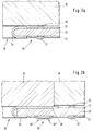
- FIG. 2a shows a first embodiment of the flat gasket 10 ′ according to the invention and a cylinder head 18 arranged adjacent to it.
- the flat gasket 10 ′ according to FIG. 2a is constructed on a carrier plate 20 and an upper and a lower metal layer 22, 23.
- the flat gasket 10 ′ according to FIG 2a shows a combustion chamber surround 24 which, as a flanged metal surround, covers the edge of the carrier plate 20 on the combustion chamber side toward the opening 12.
- the thickness of the combustion chamber surround material 24 is preferably chosen to be greater than the thickness of the metal layers 22 and 23.
- the metal layers 22 and 23 are at a distance from the opening 12, which embodies the combustion chamber, a circumferential bead 26, 27 which forms the combustion chamber seal between the engine block and the cylinder head in the installed state of the seal, ie in the pressed state.
- the combustion chamber surround 24 with its somewhat more chosen material compared to the metal layers 22 and 23 defines the minimum distance between the cylinder head and engine block and limits the compression of the beads 26 and 27 to the necessary extent.
- Figure 2b shows the same flat seal 10 'in the area of overlap with a swirl chamber 19.
- the combustion chamber surround 24 in this area on one side of the flat seal 10' has a widening 28, which the surface of the swirl chamber, which with the Flat gasket 10 'overlaps, completely covers and protrudes somewhat beyond the area of the swirl chamber 19, so that the spacer and sealing function of the combustion chamber surround 24 with its somewhat thicker material is given in this area as well as in other areas around the combustion chamber or Breakthrough 12 around too.
- the beads 26 and 27 run at a significantly greater distance from the opening 12 than in the region shown in FIG. 2a, but keep approximately the same distance from the material of the combustion chamber surround 24. This ensures that the compression the beads 26 and 27, also in the area that surrounds the swirl chamber, is essentially identical to the state as it is achieved in the flat seal area shown in FIG. 2a.
- two half beads 30, 30 ' are provided in the lower metal layer 23, which support the swirl chamber in its seat in the cylinder head.
- combustion chamber surround 24 in the area opposite the widening 28 (not shown) by integrating the two half beads 30, 30 'into the combustion chamber surround 24.
- a material of uniform thickness is used as the carrier plate material, which is why a somewhat weaker material is to be used for the metal layers 22, 23 compared to the material of the combustion chamber surround 24.
- the thickness of the materials are sufficient here, for example a difference in thickness of approximately 0.1 mm, in order to achieve very satisfactory combustion chamber seals and flat seals with a very long service life.
- An example of the dimensioning of the individual components of the seal is the thickness of the individual component materials.
- a material with a thickness of approximately 0.3 mm can be used for the combustion chamber surround 24, while a material with a thickness of approximately 0.25 mm is used for the metal layers 22 and 23.
- a material with a thickness between 0.2 and 0.7 mm is recommended for the carrier plate 20, but thicker and possibly thinner materials can also be used.
- the different installation thicknesses of the cylinder head gaskets required by the engine manufacturers can be easily realized by selecting the carrier plate thickness.
- the actual functional parts of the seal can be used in identical form with different thicknesses of the carrier plate.
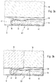
- Figures 3a and 3b show another embodiment of the invention, in which the distance between the cylinder head 18 and the engine block (not shown) by a reinforced part 32 of a support plate 34 together with the material of a combustion chamber enclosure 36 is defined.
- the combustion chamber surround is formed in one piece with an upper metal layer 38, which is flanged over the end of the support plate 34 on the combustion chamber side and surrounds the support plate 34 on the combustion chamber side.
- the upper metal layer 38 has two half beads 40, 41, of which the half bead 41 is laid flat in the assembled state, while the half bead 40 rests resiliently and sealingly on the cylinder head 18.
- metal glasses can also be placed on the carrier plate 34, which then leads to a region-wise increase in thickness corresponding to the carrier plate part 32.
- a lower metal layer 42 is arranged, which can have the same material thickness as the upper metal layer 38. Since the upper metal layer 38 with the half bead 40 already defines the combustion chamber sealing area, the lower metal layer 42 can be in the area of the The combustion chamber seal must be flat and lie flat on the carrier plate 34.
- FIG. 3 b shows the same flat gasket as shown in FIG. 3 a, but the area of the swirl chamber insert 19 that protrudes somewhat from the cylinder head 18 in the operating state shown.
- the reinforced area 32 of the carrier plate 34 is dimensioned wider, so that it extends not only over the part of the carrier plate 34 which overlaps with the swirl chamber insert 19, but additionally also in this area up to that with the cylinder head 18 overlapping area protrudes.
- the distance between the cylinder head and the engine block is again determined by the reinforced area 32 of the carrier plate 34 and the material thickness of the upper layer 38 (and of course also the lower layer 42).
- the half bead 41 here serves the resilient support of the swirl chamber 19 and ensures that it is held securely in place in the cylinder head 18 in every operating state of the engine.
- the half bead 40 runs here at a greater distance from the opening 12 and shifts the circumferential line of the combustion chamber seal out of the region of the swirl chamber insert or back into the hinterland into the region of the cylinder head 18. This ensures that a sealing effect between the entire circumferential line of the combustion chamber seal Cylinder head 18 and the upper metal layer 38 is produced so that the sealing effect is independent of the material properties and the material behavior of the swirl chamber insert 19.
- a metal ring made of flat material can also be inserted between the carrier plate 34 and the upper metal layer 38, as described at the beginning, the contours of the metal ring corresponding to the contour of the reinforced region 32.
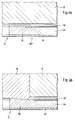
- FIGS. 4a and 4b A further alternative embodiment of the flat seal 10 is shown as a flat seal 10 '''in FIGS. 4a and 4b.
- This flat gasket has a particularly simple structure, since it knows in principle only three elements, namely a carrier plate 44, an upper metal layer 46 and a lower metal layer 48.
- the metal layers 46 and 48 are flat metal sheets which, like the carrier plate 44 to, are reach the edge of the combustion chamber.
- the edges of the carrier plate 44 and the metal layers 46 and 48 on the combustion chamber side are aligned so that they are aligned a special design of a combustion chamber surround is unnecessary, which is formed here by the flush edges of the carrier plate 44 and the metal layers 46 and 48.
- the carrier plate 44 has a reinforced area 50 at its combustion chamber end, which can run as a narrow ring around the combustion chamber or the opening 12, but in the area in which the flat gasket 10 '''coexists the swirl chamber 19 overlaps (see FIG. 4b), is designed wider than in the other areas of the flat gasket.
- This embodiment of the invention has the great advantage that the combustion chamber surround can form essentially no harmful space for harmful gases, in particular the usual gusset with flared combustion chamber surrounds is eliminated.
- This principle, shown here for the first time, of the formation of flat seals at the edge of the combustion chamber can not only be used for engines with swirl chamber inserts, but generally with the same advantage of minimizing the clearance of any type of engine.
- FIGs 5a and 5b show another alternative embodiment of the invention which is similar to the embodiment as shown in Figures 2a and 2b.
- the cylinder head gasket 10 IV shown here has an essentially flat carrier plate 52, which is sandwiched between two metal layers 54, 56.
- the upper metal layer 54 is flanged in the area of the opening 12 around the carrier plate 52 and forms the combustion chamber surround of this cylinder head gasket.
- the upper and lower metal layers 54 and 56 have beads 58, 59 spaced apart from the edge of the combustion chamber, which reinforce the pressing pressure in this area and in this case create a combustion chamber seal.
- FIG. 5b shows the situation as it arises in the area of the swirl chamber insert 19 in the cylinder head 18, 56 half-beads being formed here to support and secure the swirl chamber insert 19 in the cylinder head 18 in the lower metal layer, which collapse when the swirl chamber insert 19 retreats certain operating conditions of the engine ensure a secure fit and hold of the swirl chamber insert 19 in the cylinder head 18.
- the beads 58, 59 are moved further back from the opening 12 and run outside the area of the cylinder head gasket 10 IV , which overlaps with the swirl chamber insert 19, in the so-called hinterland.
- FIGS. 6a and 6b show a further embodiment of the invention, in which a cylinder head gasket 10 V, as essential components, comprises an upper metal layer 64, a lower metal layer 66 and a combustion chamber surround ring 68 in addition to a carrier plate 62.
- the combustion chamber surround ring 68 lies within the opening of the carrier plate 62, which is larger here than is necessary for the combustion chamber of the cylinder bore.
- the combustion chamber limitation is formed here by the bezel ring 68, which ends with an end face open towards the combustion chamber.
- the upper metal layer 64 and the lower metal layer 66 end openly with respect to the combustion chamber of the engine.
- the upper layer 64, the lower layer 66 and the combustion chamber surround ring 68 are pressed together, so that there is a substantially sealed position of these three components of the flat gasket.
- the open, quasi-sandwich-like structure ensures that the harmful space in the combustion chamber is kept to a minimum. Likewise with that at the same time, a reduction in the harmful gas zones is achieved, which is evident from the improved exhaust gas values of engines sealed in this way.
- the upper and lower metal layers 64 and 66 have, spaced apart from the combustion chamber, a negatively formed bead 70, 71 which reinforce the contact pressure in the area of the combustion chamber seal.
- the combustion chamber surround ring 68 has a greater width in the area in which it overlaps with the swirl chamber insert 19 than is otherwise the case in the area which only overlaps with the cylinder head.
- the width of the bezel ring 68 is selected in the area overlapping with the swirl chamber insert 19 such that it projects beyond this area into the area of the cylinder head 18.
- the beads 70, 71 move further away from the combustion chamber 12 in the region of the swirl chamber and define a combustion chamber seal in the region of the hinterland of the seal.
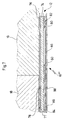
- FIG. 7 finally shows an embodiment of the invention, in which the cylinder head gasket 10 VI comprises an essentially flat carrier plate 74 which carries a sheet metal layer 76 on its side adjacent to the cylinder head 18 and the swirl chamber 19.
- the sheet metal layer 76 has two half beads 77, 78 in its area overlapping with the cylinder head 18, which are supported on the cylinder head 18 on the one hand and on the carrier plate 74 on the other hand.
- Spectacles 80 are inserted as a reinforcing part in the region of the swirl chamber 19 and comprise a bead 82 on their partial region arranged adjacent to the combustion chamber 12.
- the glasses 80 run in their facing away from the combustion chamber 12 Partly along the boundary line of cylinder head 18 and swirl chamber insert 19.
- glasses 80 are joined by a specially designed sheet-metal layer 84, which has a smaller thickness than the glasses material.
- the cylinder head gasket 10 VI finally closes on its side facing the engine block (not shown) with a further, essentially continuous sheet metal layer 86, which is flat in the area overlapping with the swirl chamber insert 19 and in the cylinder head area corresponding to the formation of the sheet metal layer 78 with two half beads 88, 89 is equipped, which are supported on the one hand on the engine block and on the sheet metal layer 84 on the other.
- the swirl chamber insert 19 is pressed particularly well into its seat in the cylinder head 18 by the beaded part of the glasses 80.
- the glasses 80 as a whole and also the beaded area 82 lead to an improvement in the gas seal.
- the deformability of the bead 82 above all compensates for the different component stiffnesses. It is also important in this embodiment that the position of the elevation or the thickened area (glasses 80) is eccentric with respect to the cross section or the layer structure of the cylinder head gasket 10 VI .
- this cylinder head gasket can also be used particularly advantageously with regard to minimizing harmful gas and reducing the harmful space in all other engine types, i.e. even those that do not have a vertebral chamber insert.
Landscapes
- Engineering & Computer Science (AREA)
- General Engineering & Computer Science (AREA)
- Mechanical Engineering (AREA)
- Gasket Seals (AREA)
Applications Claiming Priority (2)
| Application Number | Priority Date | Filing Date | Title |
|---|---|---|---|
| DE4308726 | 1993-03-19 | ||
| DE19934308726 DE4308726A1 (de) | 1993-03-19 | 1993-03-19 | Flachdichtung für Verbrennungskraftmaschinen |
Publications (1)
| Publication Number | Publication Date |
|---|---|
| EP0616154A1 true EP0616154A1 (fr) | 1994-09-21 |
Family
ID=6483175
Family Applications (1)
| Application Number | Title | Priority Date | Filing Date |
|---|---|---|---|
| EP94104366A Withdrawn EP0616154A1 (fr) | 1993-03-19 | 1994-03-19 | Joint plat pour un moteur à combustion interne |
Country Status (2)
| Country | Link |
|---|---|
| EP (1) | EP0616154A1 (fr) |
| DE (1) | DE4308726A1 (fr) |
Cited By (1)
| Publication number | Priority date | Publication date | Assignee | Title |
|---|---|---|---|---|
| EP0633396B1 (fr) * | 1993-07-07 | 1999-10-20 | NIPPON LEAKLESS INDUSTRY Co., Ltd. | Joint d'étanchéité métallique |
Families Citing this family (5)
| Publication number | Priority date | Publication date | Assignee | Title |
|---|---|---|---|---|
| DE4426508C2 (de) * | 1994-07-27 | 1998-09-24 | Payen Goetze Gmbh | Zylinderkopfdichtung |
| FR2830281B1 (fr) * | 2001-09-28 | 2003-11-28 | Meillor Sa | Joint de culasse comprenant un stoppeur bord a bord lie par agrafage |
| DE102004040784C5 (de) * | 2004-08-23 | 2016-03-03 | Reinz-Dichtungs-Gmbh | Zylinderkopfflachdichtung mit einer mehrteiligen Lage |
| DE102004064110C5 (de) | 2004-08-23 | 2019-04-04 | Reinz-Dichtungs-Gmbh | Zylinderkopfdichtung mit einer mehrteiligen Lage |
| DE102004064109C5 (de) | 2004-08-23 | 2019-03-21 | Reinz-Dichtungs-Gmbh | Verwendung einer Zylinderkopfdichtung |
Citations (4)
| Publication number | Priority date | Publication date | Assignee | Title |
|---|---|---|---|---|
| DE2856186A1 (de) * | 1978-12-27 | 1980-07-03 | Goetze Ag | Flachdichtung, insbesondere zylinderkopfdichtung |
| EP0209708A2 (fr) * | 1985-07-26 | 1987-01-28 | Goetze Ag | Dispositif d'étanchéité de culasse pour moteur à combustion interne avec chambre de précombustion dans la culasse |
| JPH01211660A (ja) * | 1988-02-17 | 1989-08-24 | Nippon Metal Gasket Kk | 積層金属ガスケット |
| EP0516406A1 (fr) * | 1991-05-30 | 1992-12-02 | Ishikawa Gasket Co. Ltd. | Joint de culasse à métal laminé |
Family Cites Families (3)
| Publication number | Priority date | Publication date | Assignee | Title |
|---|---|---|---|---|
| JPS60162037A (ja) * | 1984-02-02 | 1985-08-23 | Yuusan Gasket Kk | シリンダ・ヘツド・ガスケツト |
| JPS63143369A (ja) * | 1986-12-06 | 1988-06-15 | Kubota Ltd | 副室式エンジンのヘツドガスケツト |
| JP2518002Y2 (ja) * | 1989-11-29 | 1996-11-20 | 石川ガスケット 株式会社 | 予備燃焼室付きシリンダヘッド用ガスケット |
-
1993
- 1993-03-19 DE DE19934308726 patent/DE4308726A1/de not_active Ceased
-
1994
- 1994-03-19 EP EP94104366A patent/EP0616154A1/fr not_active Withdrawn
Patent Citations (4)
| Publication number | Priority date | Publication date | Assignee | Title |
|---|---|---|---|---|
| DE2856186A1 (de) * | 1978-12-27 | 1980-07-03 | Goetze Ag | Flachdichtung, insbesondere zylinderkopfdichtung |
| EP0209708A2 (fr) * | 1985-07-26 | 1987-01-28 | Goetze Ag | Dispositif d'étanchéité de culasse pour moteur à combustion interne avec chambre de précombustion dans la culasse |
| JPH01211660A (ja) * | 1988-02-17 | 1989-08-24 | Nippon Metal Gasket Kk | 積層金属ガスケット |
| EP0516406A1 (fr) * | 1991-05-30 | 1992-12-02 | Ishikawa Gasket Co. Ltd. | Joint de culasse à métal laminé |
Non-Patent Citations (1)
| Title |
|---|
| PATENT ABSTRACTS OF JAPAN vol. 13, no. 521 (M - 896)<3869> 21 November 1989 (1989-11-21) * |
Cited By (2)
| Publication number | Priority date | Publication date | Assignee | Title |
|---|---|---|---|---|
| EP0633396B1 (fr) * | 1993-07-07 | 1999-10-20 | NIPPON LEAKLESS INDUSTRY Co., Ltd. | Joint d'étanchéité métallique |
| US6619666B1 (en) | 1993-07-07 | 2003-09-16 | Nippon Leakless Industry Co., Ltd. | Metal gasket assembly |
Also Published As
| Publication number | Publication date |
|---|---|
| DE4308726A1 (de) | 1993-12-02 |
Similar Documents
| Publication | Publication Date | Title |
|---|---|---|
| DE3915434C2 (fr) | ||
| EP0946836B1 (fr) | Joint plat metallique | |
| DE69421214T2 (de) | Metalldichtung | |
| EP1985897A1 (fr) | Joint plat métallique | |
| DE4142600C2 (de) | Zylinderkopfdichtung | |
| DE3001730A1 (de) | Zylinderkopfdichtung | |
| DE102008020277B4 (de) | Zylinderkopfdichtung | |
| EP0740092A1 (fr) | Joint de culasse métallique | |
| EP1577590A1 (fr) | Joint de culasse | |
| DE19751293A1 (de) | Einschichtige oder mehrschichtige Metallzylinderkopfdichtung und Verfahren zu ihrer Herstellung | |
| DE102009027758A1 (de) | Motorzylinderkopfdichtungsanordnung | |
| DE10324667A1 (de) | Zylinderkopfdichtung | |
| EP0354464A2 (fr) | Joint plat | |
| EP0406730B1 (fr) | Joint de culasse de cylindre | |
| DE10244853B4 (de) | Mehrlagige Zylinderkopfdichtung | |
| EP0616154A1 (fr) | Joint plat pour un moteur à combustion interne | |
| DE3313438A1 (de) | Zylinderkopfdichtung | |
| EP0557918B1 (fr) | Joint pour moteur à combustion interne | |
| DE19513361C1 (de) | Metallische Zylinderkopfdichtung | |
| DE19809755B4 (de) | Zylinderkopfdichtung | |
| EP0619447B1 (fr) | Joint plat métallique | |
| EP2138745B1 (fr) | Joint de culasse | |
| DE19523825A1 (de) | Metallische Flachdichtung | |
| EP0616124B1 (fr) | Joint de culasse à plusieurs couches pour un moteur à combustion interne | |
| EP1271018B1 (fr) | Joint d'étanchéité plat |
Legal Events
| Date | Code | Title | Description |
|---|---|---|---|
| PUAI | Public reference made under article 153(3) epc to a published international application that has entered the european phase |
Free format text: ORIGINAL CODE: 0009012 |
|
| AK | Designated contracting states |
Kind code of ref document: A1 Designated state(s): BE DE FR GB IT |
|
| 17P | Request for examination filed |
Effective date: 19940804 |
|
| 17Q | First examination report despatched |
Effective date: 19960131 |
|
| STAA | Information on the status of an ep patent application or granted ep patent |
Free format text: STATUS: THE APPLICATION IS DEEMED TO BE WITHDRAWN |
|
| 18D | Application deemed to be withdrawn |
Effective date: 19960813 |