EP0616230A1 - Aimant pour champ homogène avec un arrangement de disques polaires séparés par des espaces d'air de correction pour chaque pièce polaire - Google Patents
Aimant pour champ homogène avec un arrangement de disques polaires séparés par des espaces d'air de correction pour chaque pièce polaire Download PDFInfo
- Publication number
- EP0616230A1 EP0616230A1 EP94103114A EP94103114A EP0616230A1 EP 0616230 A1 EP0616230 A1 EP 0616230A1 EP 94103114 A EP94103114 A EP 94103114A EP 94103114 A EP94103114 A EP 94103114A EP 0616230 A1 EP0616230 A1 EP 0616230A1
- Authority
- EP
- European Patent Office
- Prior art keywords
- pole plate
- pole
- facing
- plate elements
- gap
- Prior art date
- Legal status (The legal status is an assumption and is not a legal conclusion. Google has not performed a legal analysis and makes no representation as to the accuracy of the status listed.)
- Granted
Links
Images

Classifications
-
- H—ELECTRICITY
- H01—ELECTRIC ELEMENTS
- H01F—MAGNETS; INDUCTANCES; TRANSFORMERS; SELECTION OF MATERIALS FOR THEIR MAGNETIC PROPERTIES
- H01F7/00—Magnets
- H01F7/02—Permanent magnets [PM]
- H01F7/0273—Magnetic circuits with PM for magnetic field generation
- H01F7/0278—Magnetic circuits with PM for magnetic field generation for generating uniform fields, focusing, deflecting electrically charged particles
-
- G—PHYSICS
- G01—MEASURING; TESTING
- G01R—MEASURING ELECTRIC VARIABLES; MEASURING MAGNETIC VARIABLES
- G01R33/00—Arrangements or instruments for measuring magnetic variables
- G01R33/20—Arrangements or instruments for measuring magnetic variables involving magnetic resonance
- G01R33/28—Details of apparatus provided for in groups G01R33/44 - G01R33/64
- G01R33/38—Systems for generation, homogenisation or stabilisation of the main or gradient magnetic field
- G01R33/383—Systems for generation, homogenisation or stabilisation of the main or gradient magnetic field using permanent magnets
Definitions
- the invention relates to a homogeneous field magnet with a yoke guiding the magnetic flux and two opposite pole pieces, between which a useful volume is formed with a magnetic field of high homogeneity, each pole piece being provided with a pole plate device which is opposite a base part of the respective pole piece facing the yoke is spaced apart via a narrow correction air gap and contains at least two mutually parallel pole plate elements made of different materials.
- a corresponding homogeneous field magnet is e.g. can be seen from EP 0 488 015 A1.
- Homogeneous field magnets are particularly necessary for the generation of basic magnetic fields in nuclear magnetic resonance imaging (nuclear magnetic resonance tomography, imaging or spectroscopy) systems.
- the magnetic field of such basic field magnets must be sufficiently homogeneous in an imaging or examination area (usable volume) and generate a predetermined magnetic induction B O there .
- Superconducting coil systems are generally provided for magnetic induction B O > 0.5 T.
- lower magnetic induction B O ⁇ 0.5 T can also be generated with normally conductive coils or permanent magnets.
- the latter magnets are common designed as a so-called pole shoe magnet with a magnetic yoke in the form of a "C" or "H". The useful volume with the required field homogeneity then lies between the pole faces of their opposite pole shoes.
- the initially achievable field homogeneity in the usable volume is not sufficient, in particular for the requirements of magnetic resonance imaging, because of the inevitable manufacturing tolerances. Rather, there must be a possibility of correction on the finished magnet in order to be able to successively reduce the field error by an alternating sequence of field measurements and field corrections (so-called "shim procedure").
- a pole shoe magnet emerges from the aforementioned EP-A, which has mechanical field correction possibilities.
- its pole pieces are designed in the area of their pole faces from adjustable pole plate devices.
- the surfaces of the pole shoes facing the useful volume can be profiled in such a way that, in particular, edge effects which influence the homogeneity are compensated for.
- each of the pole plate devices is not directly attached to the magnetic yoke carrying a magnetic flux. Rather, each pole plate device is spaced apart from a base part of the pole shoe facing the yoke by a narrow correction air gap, wherein it is designed to be tiltable and / or bendable by means of special adjusting devices is.
- the air gap acts as a magnetic series resistance to homogenize the field by compensating for flux density inhomogeneities in flux-carrying parts of the pole shoe when it enters the respective pole plate device.
- each of its pole plate devices can also be formed by a stack-like structure made of two layer-like pole plate elements of approximately the same thickness, different soft magnetic materials being selected for these elements.
- the first pole plate element facing the correction air gap can be produced, for example, from at least one electrical sheet made of an Fe-Si alloy, with sufficient flexibility of the element being ensured.
- the second pole plate element facing the usable volume can consist, for example, of a soft magnetic ferrite or of a plastic-bonded iron powder.
- a relative permeability ⁇ r of about 1000 and a flow capacity B max of about 0.4 T to 0.5 T of the material of this second layer this material advantageously has only a low electrical conductivity.
- the first layer should ensure good basic field homogeneity. For this purpose it consists of a material with a relative permeability ⁇ r between 1000 and 5000 with a high flow capacity B max of about 1.6 T.
- Such plate devices also carry a magnetic flux generated by pulsed gradient coils. It it then turns out, however, that magnetic hysteresis of the plate material leads to residual fields after a gradient pulse and to a non-linear current-field relationship. As a result, the image quality of known imaging methods, such as, for example, the method referred to as "turbo spin echo" can be impaired.
- the occurrence of hysteresis is also a cause of errors in the basic magnetic field. Depending on whether an operating current of existing excitation coils is reached from lower or higher values, there is a different spectrum of field errors. This fact complicates a shim procedure for setting an optimal basic field homogeneity.
- pole plate elements are mutually spaced by a gap of predetermined width and that on each pole piece the pole plate element facing the base part consists of a material whose relative permeability is at least a factor 5 less than the relative permeability of the material of the the useful volume facing pole plate element, which is at least 10,000.
- the advantages associated with this configuration of the homogeneous field magnet can be seen, in particular, in the fact that the highly permeable material faces the usable volume
- the pole plate element shows only a slight hysteresis.
- This pole plate element essentially carries the magnetic gradient flux, which consequently is only influenced to a correspondingly small extent by residual errors after a gradient pulse.
- the radial flux distribution of the basic magnetic field essentially takes over the pole plate element facing the base part of the pole piece. Hysteresis effects only play a minor role in this element.
- the gap between the two pole plate elements is a magnetic decoupling device.
- This gap prevents the radial flow in the pole plate element facing the base part from passing into the highly permeable material of the parallel plate element and being able to magnetically saturate it.
- Known highly permeable materials which have a comparatively lower magnetic saturation induction B s than the materials of the pole plate elements facing the base part can therefore advantageously be used for these pole plate elements.
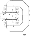
- FIG. 1 shows a basic embodiment of a homogeneous field magnet.
- FIG. 2 shows an enlarged section of a pole piece of this magnet designed according to the invention.
- identical parts are provided with the same reference symbols.
- the homogeneous field magnet shown in the schematic longitudinal section in FIG. 1 is generally designated by 2. It has a one-leg magnetic yoke 3 e.g. made of iron in the form of a "C".
- the two opposite, free leg ends 3a and 3b of the yoke 3 each open into an at least approximately cylindrical core 4 or 5 made of ferromagnetic material. These cores leading towards one another are each enclosed by their own excitation coil 7 or 8.
- the two cores 4 and 5 On the sides facing away from the leg ends 3a and 3b, the two cores 4 and 5 each merge into a widening pole shoe 10 and 11, respectively. This results in a structure of the entire magnet 2 that is at least largely symmetrical with respect to a plane of symmetry E.
- a space or useful volume N is formed between the pole faces 10a and 11a of the two pole shoes 10 and 11, which are spaced apart by a distance A.
- this useful volume there should be a magnetic field with magnetic induction B O which is sufficiently homogeneous for magnetic resonance imaging and which is caused by the two excitation coils 7 and 8.
- Each of the pole pieces 10 and 11 contains a magnetic flux Base part 10b or 11b, which is connected to the yoke 3 via the respective core 4 or 5.
- Each base part 10b or 11b has a free surface which is practically flat except for an edge area and has a bead-like edge piece 10c or 11c in the edge area which reduces the mutual distance A.
- These ring-shaped edge pieces are used for field correction.
- a special pole plate device 12 or 13 designed according to the invention is arranged in each inner, central region of the pole shoes bounded by these edge pieces.
- Each of these pole plate devices 12 and 13 should be spaced apart from the respectively assigned base part 10b or 11b by a narrow, axial correction air gap 14 or 15.
- gradient coils (not shown) for generating pulsed gradient fields required for magnetic resonance imaging are generally located in the immediate vicinity of the surfaces 10a and 11a of the pole plate devices 12 and 13 facing the useful volume N.
- FIG. 1 shows an enlarged section of part of one of the two pole pieces of the magnet 2 according to FIG. 1, for example the pole piece 10.
- FIG. 1 shows an enlarged section of part of one of the two pole pieces of the magnet 2 according to FIG. 1, for example the pole piece 10.
- Corresponding design features should also be provided for the pole piece 11.
- the base part 10b having a largely trapezoidal cut surface has a stepped surface 16 evident.
- This surface is divided into a central surface part 16a of a central, central pole region 17a and an outer surface part 16b of an edge region 17b.
- a step 18 is formed between these two areas, so that there is an edge piece 10c of the base part.
- the edge piece can, for example, have a trapezoidal or rectangular cross-sectional area. It can be formed in one piece with the base part 10b or can be attached to the base part as a separate component.
- the base part can also be profiled in another form.
- the pole plate device 12 In the central, central pole region 17a, the pole plate device 12 is arranged separated from the surface part 16a by a narrow axial correction air gap 14 of width a. A radial gap 20 should remain between the outer edge of the pole plate device and the edge piece 10c. Adjusting devices for fixing and for tilting and / or bending the pole plate device 12 are well known (cf. e.g. the aforementioned DE-OS 37 37 133). They are therefore omitted from the drawing.
- the entire pole plate device 12 (and accordingly also the entire pole plate device 13) generally has a rectangular cross-sectional area, wherein it is designed to be relatively thin compared to its radius R. So their constant thickness D is generally between 0.3 and 3 cm, preferably between 5 and 15 mm. According to the invention, the pole plate device 12 is to be divided into two pole plate elements 12a and 12b be aligned parallel to each other and spaced by a gap 22 of width w.
- the pole plate element 12a facing the base part 10b is to consist of a soft magnetic material, the relative permeability ⁇ r 1 of which is at least a factor 5, preferably at least a factor 10, lower than the relative permeability ⁇ r 2 of the soft magnetic material used for the the pole plate element 12b facing the useful volume N is provided.
- the relative permeability ⁇ r 2 should be at least 10,000, preferably at least 50,000.
- the two pole plate elements 12a and 12b also have different thicknesses d1 and d2, where d1> d2.
- the thickness d1 of the pole plate element 12a is generally between 3 and 25 mm, while a thickness d2 between 1 and 5 mm is generally chosen for the pole plate element 12b.
- the thus thicker pole plate element 12a essentially takes over the radial flux distribution of the basic magnetic field. It should therefore consist of a material with a sufficiently high magnetic saturation induction B s . Pure iron (B s ⁇ 1.8 T) or Fe-Si alloys with Si contents between 2 and 7 atom% (B s > 1.5 T) are therefore preferably suitable for this. These materials have a relative permeability ⁇ r 1, which is generally between 1000 and 5000. In contrast, the magnetic gradient flux generated by the gradient coils is essentially only detected by the thinner pole plate element 12b made of the highly permeable material.
- materials with a particularly low magnetic coercive force H c should be selected.
- Materials that meet these requirements are in particular special Fe-Ni alloys with a Ni content between 40 and 85 atom%. Examples of such alloys are the materials with the trade name "MUMETALL” (with 72 to 83 atom% Ni) and “PERMENORM 5000" (with 45 to 50 atom% Ni) from "Vacuumschmelze GmbH", Hanau, DE (cf. also the book of this company "soft magnetic materials", 4th edition, 1990, pages 278 and 279).
- a sufficient width w of the gap 22 is essential for the homogeneous magnet according to the invention, in order to ensure sufficient magnetic decoupling between the two pole plate elements 12a and 12b. Otherwise, radial magnetic flux would pass from the pole plate element 12a into the highly permeable pole plate element 12b and magnetically saturate it. That is, saturation of the highly permeable material of the pole plate element 12b due to a magnetic field strength H caused by the pole plate element 12a must be prevented, that is, a magnetic short circuit must be avoided.
- the source of the field strength H can be the radial magnetic flux in the pole plate element 12a or the coercive field strength H c of its material.
- B ' ⁇ O * H c * R2 / (8 * w * d2)
- B ' is the magnetic induction caused in the pole plate element 12b.
- B ' should at most about 1/5 to 2/3, preferably 1/3 to 1/2 of the saturation induction B.
- H c is the coercive force of the material of the pole plate element 12a.
- ⁇ O is the universal magnetic field constant.
- the gap 22 between the pole plate elements 12a and 12b can advantageously by a plate made of plastic or a non-magnetic metal such as aluminum or Copper to be filled out.
- a compact, manageable component as a pole plate device 12 is then formed from the stack of plates comprising the elements 12a, 12b and the plate filling the gap 22, for example by gluing or by a large number of thin non-magnetic screws.
Landscapes
- Physics & Mathematics (AREA)
- Electromagnetism (AREA)
- Engineering & Computer Science (AREA)
- Power Engineering (AREA)
- Condensed Matter Physics & Semiconductors (AREA)
- General Physics & Mathematics (AREA)
- Magnetic Resonance Imaging Apparatus (AREA)
Applications Claiming Priority (2)
| Application Number | Priority Date | Filing Date | Title |
|---|---|---|---|
| DE4308208 | 1993-03-15 | ||
| DE4308208 | 1993-03-15 |
Publications (2)
| Publication Number | Publication Date |
|---|---|
| EP0616230A1 true EP0616230A1 (fr) | 1994-09-21 |
| EP0616230B1 EP0616230B1 (fr) | 1998-08-05 |
Family
ID=6482852
Family Applications (1)
| Application Number | Title | Priority Date | Filing Date |
|---|---|---|---|
| EP94103114A Expired - Lifetime EP0616230B1 (fr) | 1993-03-15 | 1994-03-02 | Aimant pour champ homogène avec un arrangement de disques polaires séparés par des espaces d'air de correction pour chaque pièce polaire |
Country Status (4)
| Country | Link |
|---|---|
| US (1) | US5363078A (fr) |
| EP (1) | EP0616230B1 (fr) |
| JP (1) | JP3514806B2 (fr) |
| DE (1) | DE59406586D1 (fr) |
Cited By (2)
| Publication number | Priority date | Publication date | Assignee | Title |
|---|---|---|---|---|
| DE19813211C2 (de) * | 1998-03-25 | 2000-05-18 | Siemens Ag | Supraleitende Einrichtung mit Leitern aus Hoch-T¶c¶-Supraleitermaterial |
| US7260941B2 (en) | 2002-05-15 | 2007-08-28 | Siemens Aktiengesellschaft | Superconductor device having superconductive magnet and refrigeration unit |
Families Citing this family (12)
| Publication number | Priority date | Publication date | Assignee | Title |
|---|---|---|---|---|
| FI933834A7 (fi) * | 1993-09-01 | 1995-03-02 | Picker Nordstar Oy | Magneettikuvauslaitteen napakenkä |
| JP3143371B2 (ja) * | 1995-09-19 | 2001-03-07 | 信越化学工業株式会社 | 磁気共鳴イメージング装置 |
| JP3014319B2 (ja) * | 1996-04-12 | 2000-02-28 | 信越化学工業株式会社 | 磁石対向型永久磁石回路 |
| JP3283242B2 (ja) * | 1999-06-21 | 2002-05-20 | ジーイー横河メディカルシステム株式会社 | 勾配コイルの製造方法、勾配コイルおよびmri装置 |
| JP3705995B2 (ja) * | 2000-04-19 | 2005-10-12 | ジーイー・メディカル・システムズ・グローバル・テクノロジー・カンパニー・エルエルシー | 勾配コイル製造方法および勾配コイル並びに磁気共鳴撮影装置 |
| JP4051301B2 (ja) * | 2003-02-12 | 2008-02-20 | ジーイー・メディカル・システムズ・グローバル・テクノロジー・カンパニー・エルエルシー | 円形ポールピースおよびmri装置 |
| CN100434928C (zh) * | 2003-05-23 | 2008-11-19 | 西门子(中国)有限公司 | 一种可用于磁共振设备的磁场发生系统 |
| JP5234990B2 (ja) | 2009-05-13 | 2013-07-10 | 住友重機械工業株式会社 | 軸受構造 |
| JP6281677B2 (ja) * | 2013-03-08 | 2018-02-21 | 国立大学法人名古屋大学 | 磁気計測装置 |
| US9933392B2 (en) * | 2015-09-30 | 2018-04-03 | The Boeing Company | Apparatus, system, and method for non-destructive ultrasonic inspection |
| US10991497B2 (en) * | 2016-02-03 | 2021-04-27 | Adaptas Solutions Pty Ltd | Apparatus and methods for controlling a charged particle in a magnetic field |
| CA3122152A1 (fr) * | 2018-12-06 | 2020-06-11 | Board Of Supervisors Of Louisiana State University And Agricultural And Mechanical College | Procede et systeme pour appliquer d'une maniere extremement homogene des champs electriques pulses a l'aide de noyaux magnetiques |
Citations (7)
| Publication number | Priority date | Publication date | Assignee | Title |
|---|---|---|---|---|
| EP0170318A1 (fr) * | 1984-07-17 | 1986-02-05 | Koninklijke Philips Electronics N.V. | Appareil à résonance magnétique nucléaire avec un aimant permanent |
| JPS61203605A (ja) * | 1985-03-07 | 1986-09-09 | Fuji Electric Co Ltd | 高均一磁場マグネツト |
| US4675609A (en) * | 1985-09-18 | 1987-06-23 | Fonar Corporation | Nuclear magnetic resonance apparatus including permanent magnet configuration |
| EP0284439A1 (fr) * | 1987-03-27 | 1988-09-28 | Sumitomo Special Metals Co. Ltd. | Dispositif pour la génération d'un champ magnétique |
| DE3737133A1 (de) * | 1987-11-02 | 1989-05-11 | Siemens Ag | Homogenfeldmagnet mit profilierten polplatten |
| EP0488015A1 (fr) * | 1990-11-30 | 1992-06-03 | Siemens Aktiengesellschaft | Aimant pour champ homogène avec au moins une pièce polaire ajustable mécaniquement |
| US5278534A (en) * | 1992-09-01 | 1994-01-11 | New York University | Magnetic structure having a mirror |
Family Cites Families (8)
| Publication number | Priority date | Publication date | Assignee | Title |
|---|---|---|---|---|
| DE1234874B (de) * | 1955-07-22 | 1967-02-23 | Perkin Elmer Corp | Vorrichtung zur Erzeugung eines homogenen magnetischen Feldes |
| US2917682A (en) * | 1956-07-09 | 1959-12-15 | Schlumberger Well Surv Corp | Magnet |
| GB1084542A (en) * | 1963-04-01 | 1967-09-27 | Perkin Elmer Ltd | Magnets with high-homogeneity working gap |
| US3223897A (en) * | 1963-09-23 | 1965-12-14 | Varian Associates | Apparatus for adjusting the configuration of a magnetic field |
| GB1360606A (en) * | 1971-08-05 | 1974-07-17 | Parker L K | Magnetic systems |
| DE3566185D1 (en) * | 1984-04-11 | 1988-12-15 | Sumitomo Spec Metals | Magnetic field generating device for nmr-ct |
| JPS63199403A (ja) * | 1987-02-14 | 1988-08-17 | Hitachi Metals Ltd | 磁界発生装置 |
| JPH03273602A (ja) * | 1990-03-23 | 1991-12-04 | Seiko Epson Corp | 磁界発生装置 |
-
1994
- 1994-03-02 EP EP94103114A patent/EP0616230B1/fr not_active Expired - Lifetime
- 1994-03-02 DE DE59406586T patent/DE59406586D1/de not_active Expired - Lifetime
- 1994-03-09 US US08/209,031 patent/US5363078A/en not_active Expired - Lifetime
- 1994-03-10 JP JP06655494A patent/JP3514806B2/ja not_active Expired - Lifetime
Patent Citations (7)
| Publication number | Priority date | Publication date | Assignee | Title |
|---|---|---|---|---|
| EP0170318A1 (fr) * | 1984-07-17 | 1986-02-05 | Koninklijke Philips Electronics N.V. | Appareil à résonance magnétique nucléaire avec un aimant permanent |
| JPS61203605A (ja) * | 1985-03-07 | 1986-09-09 | Fuji Electric Co Ltd | 高均一磁場マグネツト |
| US4675609A (en) * | 1985-09-18 | 1987-06-23 | Fonar Corporation | Nuclear magnetic resonance apparatus including permanent magnet configuration |
| EP0284439A1 (fr) * | 1987-03-27 | 1988-09-28 | Sumitomo Special Metals Co. Ltd. | Dispositif pour la génération d'un champ magnétique |
| DE3737133A1 (de) * | 1987-11-02 | 1989-05-11 | Siemens Ag | Homogenfeldmagnet mit profilierten polplatten |
| EP0488015A1 (fr) * | 1990-11-30 | 1992-06-03 | Siemens Aktiengesellschaft | Aimant pour champ homogène avec au moins une pièce polaire ajustable mécaniquement |
| US5278534A (en) * | 1992-09-01 | 1994-01-11 | New York University | Magnetic structure having a mirror |
Non-Patent Citations (2)
| Title |
|---|
| M.G. ABELE ET AL.: "FIELD COMPUTATION IN PERMANENT MAGNETS", IEEE TRANSACTIONS ON MAGNETICS, vol. 28, no. 1, 1 January 1992 (1992-01-01), NEW YORK US, pages 931 - 934, XP000258114, DOI: doi:10.1109/20.120031 * |
| PATENT ABSTRACTS OF JAPAN vol. 11, no. 36 (E - 477)<2483> 3 February 1987 (1987-02-03) * |
Cited By (2)
| Publication number | Priority date | Publication date | Assignee | Title |
|---|---|---|---|---|
| DE19813211C2 (de) * | 1998-03-25 | 2000-05-18 | Siemens Ag | Supraleitende Einrichtung mit Leitern aus Hoch-T¶c¶-Supraleitermaterial |
| US7260941B2 (en) | 2002-05-15 | 2007-08-28 | Siemens Aktiengesellschaft | Superconductor device having superconductive magnet and refrigeration unit |
Also Published As
| Publication number | Publication date |
|---|---|
| EP0616230B1 (fr) | 1998-08-05 |
| JP3514806B2 (ja) | 2004-03-31 |
| US5363078A (en) | 1994-11-08 |
| DE59406586D1 (de) | 1998-09-10 |
| JPH06302424A (ja) | 1994-10-28 |
Similar Documents
| Publication | Publication Date | Title |
|---|---|---|
| DE69129687T2 (de) | Vorrichtung zur Erzeugung eines Magnetfeldes für die Bildgebung mittels magnetischer Resonanz | |
| DE69325255T2 (de) | Verbesserungen an Magneten der Bilderzeugung mittels magnetischer Resonanz | |
| DE69613061T2 (de) | Magnetkreisanordnung mit einander gegenüberliegenden Permanentmagneten | |
| DE1946059C3 (de) | Spulenanordnung zur Feldhomogenisierung | |
| EP0616230B1 (fr) | Aimant pour champ homogène avec un arrangement de disques polaires séparés par des espaces d'air de correction pour chaque pièce polaire | |
| EP1079236B1 (fr) | Assemblage d'aimants supraconducteurs comportant un "shim Z2" | |
| DE3616078C2 (fr) | ||
| EP0525246A1 (fr) | Dispositif à aimant avec un corp de joug pour produire un champ de fuite | |
| DE69936494T2 (de) | Magnetresonanzsystem mit Shim-Ringen | |
| DE69409915T2 (de) | Elektropneumatischer Wandler | |
| EP0011335A1 (fr) | Structure de bobine magnétique pour produire un champ magnétique homogène | |
| EP0488015B1 (fr) | Aimant pour champ homogène avec au moins une pièce polaire ajustable mécaniquement | |
| DE3523593A1 (de) | Beschleunigungsmessgeraet | |
| EP0766094B1 (fr) | Arrangement d'aimants pour un appareil diagnostique de résonance magnétique | |
| DE102009045373A1 (de) | Kompakte supraleitende Magnetanordnung mit aktiver Abschirmung, wobei die Abschirmspule das Feldmaximum der Hauptfeldspule dämpft | |
| DE2136237C3 (de) | Kernresonanzmagnetometer | |
| DE19821739C1 (de) | Mobiles Kernspinresonanzgerät | |
| DE69700319T2 (de) | Magnetanordnung für die bildgebende magnetische Resonanz mit gegenüberliegenden Permanentmagneten | |
| DE3814260A1 (de) | Vorrichtung zum erzeugen von magnetfeldern fuer ein magnetresonanz-bildgeraet | |
| EP3695213B1 (fr) | Capteur pour un dispositif de résonance de spin nucléaire | |
| EP0181383A1 (fr) | Tomographe a resonance de spin. | |
| DE102005028572A1 (de) | Magnetkern für einen Stromsensor | |
| DE69131940T2 (de) | Apparat zur Erzeugung von Magnetfeldern für die Bildgebung mittels magnetischer Resonanz | |
| EP0177869B1 (fr) | Aménagement d'un aimant avec un dispositif d'écran pour une installation de tomographie de spin nucléaire | |
| EP0505595A1 (fr) | Moteur pas-à-pas pour pièces d'horlogerie |
Legal Events
| Date | Code | Title | Description |
|---|---|---|---|
| PUAI | Public reference made under article 153(3) epc to a published international application that has entered the european phase |
Free format text: ORIGINAL CODE: 0009012 |
|
| AK | Designated contracting states |
Kind code of ref document: A1 Designated state(s): DE FR GB IT |
|
| 17P | Request for examination filed |
Effective date: 19950307 |
|
| GRAG | Despatch of communication of intention to grant |
Free format text: ORIGINAL CODE: EPIDOS AGRA |
|
| 17Q | First examination report despatched |
Effective date: 19971030 |
|
| GRAG | Despatch of communication of intention to grant |
Free format text: ORIGINAL CODE: EPIDOS AGRA |
|
| GRAH | Despatch of communication of intention to grant a patent |
Free format text: ORIGINAL CODE: EPIDOS IGRA |
|
| GRAH | Despatch of communication of intention to grant a patent |
Free format text: ORIGINAL CODE: EPIDOS IGRA |
|
| GRAA | (expected) grant |
Free format text: ORIGINAL CODE: 0009210 |
|
| AK | Designated contracting states |
Kind code of ref document: B1 Designated state(s): DE FR GB IT |
|
| REF | Corresponds to: |
Ref document number: 59406586 Country of ref document: DE Date of ref document: 19980910 |
|
| GBT | Gb: translation of ep patent filed (gb section 77(6)(a)/1977) |
Effective date: 19981012 |
|
| ET | Fr: translation filed | ||
| PLBE | No opposition filed within time limit |
Free format text: ORIGINAL CODE: 0009261 |
|
| STAA | Information on the status of an ep patent application or granted ep patent |
Free format text: STATUS: NO OPPOSITION FILED WITHIN TIME LIMIT |
|
| 26N | No opposition filed | ||
| PGFP | Annual fee paid to national office [announced via postgrant information from national office to epo] |
Ref country code: FR Payment date: 20010327 Year of fee payment: 8 |
|
| REG | Reference to a national code |
Ref country code: GB Ref legal event code: IF02 |
|
| PG25 | Lapsed in a contracting state [announced via postgrant information from national office to epo] |
Ref country code: FR Free format text: LAPSE BECAUSE OF NON-PAYMENT OF DUE FEES Effective date: 20021129 |
|
| REG | Reference to a national code |
Ref country code: FR Ref legal event code: ST |
|
| PG25 | Lapsed in a contracting state [announced via postgrant information from national office to epo] |
Ref country code: IT Free format text: LAPSE BECAUSE OF NON-PAYMENT OF DUE FEES;WARNING: LAPSES OF ITALIAN PATENTS WITH EFFECTIVE DATE BEFORE 2007 MAY HAVE OCCURRED AT ANY TIME BEFORE 2007. THE CORRECT EFFECTIVE DATE MAY BE DIFFERENT FROM THE ONE RECORDED. Effective date: 20050302 |
|
| PGRI | Patent reinstated in contracting state [announced from national office to epo] |
Ref country code: IT Effective date: 20080301 |
|
| PG25 | Lapsed in a contracting state [announced via postgrant information from national office to epo] |
Ref country code: DE Free format text: LAPSE BECAUSE OF NON-PAYMENT OF DUE FEES Effective date: 20111001 |
|
| PGFP | Annual fee paid to national office [announced via postgrant information from national office to epo] |
Ref country code: IT Payment date: 20120328 Year of fee payment: 19 |
|
| PGFP | Annual fee paid to national office [announced via postgrant information from national office to epo] |
Ref country code: GB Payment date: 20130311 Year of fee payment: 20 |
|
| PGFP | Annual fee paid to national office [announced via postgrant information from national office to epo] |
Ref country code: DE Payment date: 20130521 Year of fee payment: 20 |
|
| REG | Reference to a national code |
Ref country code: DE Ref legal event code: R071 Ref document number: 59406586 Country of ref document: DE |
|
| REG | Reference to a national code |
Ref country code: GB Ref legal event code: PE20 Expiry date: 20140301 |
|
| PG25 | Lapsed in a contracting state [announced via postgrant information from national office to epo] |
Ref country code: DE Free format text: LAPSE BECAUSE OF EXPIRATION OF PROTECTION Effective date: 20140304 Ref country code: GB Free format text: LAPSE BECAUSE OF EXPIRATION OF PROTECTION Effective date: 20140301 |