EP0616231B1 - Verfahren und Messanordnung zum Messen des Volumenstromes in einer Schicht mit reflektierender Struktur - Google Patents
Verfahren und Messanordnung zum Messen des Volumenstromes in einer Schicht mit reflektierender Struktur Download PDFInfo
- Publication number
- EP0616231B1 EP0616231B1 EP94109331A EP94109331A EP0616231B1 EP 0616231 B1 EP0616231 B1 EP 0616231B1 EP 94109331 A EP94109331 A EP 94109331A EP 94109331 A EP94109331 A EP 94109331A EP 0616231 B1 EP0616231 B1 EP 0616231B1
- Authority
- EP
- European Patent Office
- Prior art keywords
- volume
- volume element
- layer
- echo
- echoes
- Prior art date
- Legal status (The legal status is an assumption and is not a legal conclusion. Google has not performed a legal analysis and makes no representation as to the accuracy of the status listed.)
- Expired - Lifetime
Links
Images


Classifications
-
- G—PHYSICS
- G01—MEASURING; TESTING
- G01S—RADIO DIRECTION-FINDING; RADIO NAVIGATION; DETERMINING DISTANCE OR VELOCITY BY USE OF RADIO WAVES; LOCATING OR PRESENCE-DETECTING BY USE OF THE REFLECTION OR RERADIATION OF RADIO WAVES; ANALOGOUS ARRANGEMENTS USING OTHER WAVES
- G01S15/00—Systems using the reflection or reradiation of acoustic waves, e.g. sonar systems
- G01S15/88—Sonar systems specially adapted for specific applications
- G01S15/89—Sonar systems specially adapted for specific applications for mapping or imaging
- G01S15/8906—Short-range imaging systems; Acoustic microscope systems using pulse-echo techniques
- G01S15/8909—Short-range imaging systems; Acoustic microscope systems using pulse-echo techniques using a static transducer configuration
- G01S15/8915—Short-range imaging systems; Acoustic microscope systems using pulse-echo techniques using a static transducer configuration using a transducer array
- G01S15/8925—Short-range imaging systems; Acoustic microscope systems using pulse-echo techniques using a static transducer configuration using a transducer array the array being a two-dimensional transducer configuration, i.e. matrix or orthogonal linear arrays
-
- A—HUMAN NECESSITIES
- A61—MEDICAL OR VETERINARY SCIENCE; HYGIENE
- A61B—DIAGNOSIS; SURGERY; IDENTIFICATION
- A61B8/00—Diagnosis using ultrasonic, sonic or infrasonic waves
- A61B8/06—Measuring blood flow
-
- G—PHYSICS
- G01—MEASURING; TESTING
- G01S—RADIO DIRECTION-FINDING; RADIO NAVIGATION; DETERMINING DISTANCE OR VELOCITY BY USE OF RADIO WAVES; LOCATING OR PRESENCE-DETECTING BY USE OF THE REFLECTION OR RERADIATION OF RADIO WAVES; ANALOGOUS ARRANGEMENTS USING OTHER WAVES
- G01S15/00—Systems using the reflection or reradiation of acoustic waves, e.g. sonar systems
- G01S15/88—Sonar systems specially adapted for specific applications
- G01S15/89—Sonar systems specially adapted for specific applications for mapping or imaging
- G01S15/8906—Short-range imaging systems; Acoustic microscope systems using pulse-echo techniques
- G01S15/8979—Combined Doppler and pulse-echo imaging systems
-
- G—PHYSICS
- G01—MEASURING; TESTING
- G01S—RADIO DIRECTION-FINDING; RADIO NAVIGATION; DETERMINING DISTANCE OR VELOCITY BY USE OF RADIO WAVES; LOCATING OR PRESENCE-DETECTING BY USE OF THE REFLECTION OR RERADIATION OF RADIO WAVES; ANALOGOUS ARRANGEMENTS USING OTHER WAVES
- G01S7/00—Details of systems according to groups G01S13/00, G01S15/00, G01S17/00
- G01S7/52—Details of systems according to groups G01S13/00, G01S15/00, G01S17/00 of systems according to group G01S15/00
- G01S7/52017—Details of systems according to groups G01S13/00, G01S15/00, G01S17/00 of systems according to group G01S15/00 particularly adapted to short-range imaging
- G01S7/52053—Display arrangements
- G01S7/52057—Cathode ray tube displays
- G01S7/5206—Two-dimensional coordinated display of distance and direction; B-scan display
- G01S7/52061—Plan position indication (PPI display); C-scan display
Definitions
- the present invention relates to a method and a measuring arrangement according to the preamble of claim 1 or according to the preamble of claim 14.
- phased array sector scanners it is also known, by means of so-called phased array sector scanners, the sound beam in a die Sender / target axis contained by different levels Transmitter excitation to deflect differently and so scattering center speeds along each the currently activated PA axis, sequentially in different directions in said Level, so sequentially in this Cutting plane, in the "B mode" known to the person skilled in the art the two-dimensional speed field is scanned becomes.
- the present invention aims to Process of the type mentioned above or a corresponding one To create device by means of which the Volume flow in a layer with reflective Structure can be measured.
- the transmit wave packets to generate so that the layer is not coherent to achieve this non-coherence (phase inequality) arithmetically, by taking into account of locally different distances between transmitters and volume elements of the layer, are preferred according to the wording of claim 2
- the transmit wave packets are preferred produced according to the wording of claim 3, with what it by stimulating the intended in time and in phase
- Plenty of sources will be possible, if necessary existing differences in the distances between individual sources and individual volume elements the layer to take into account.
- Through the time and in-phase stimulation is achieved that how also the layer of interest spatially may be the majority of the sources provided generated collectively by the plurality of sources Transmit wave packets, as preferably requested, impinge coherently on the layer of interest.
- the transmission wave packets if they are by means of a Plurality of sources are generated, preferably produced according to the wording of claim 7. After that necessary time and phase shifts the suggestions of the individual sources defined with reference to the reference signal mentioned.
- the reference signal for demodulating the echo signals used, preferably this demodulation the electrical side of the actually as sound pressure / electrical Transformer trained sensor made becomes.
- the echoes in particular the volume element echoes from each sensor digitized and stored, preferably after demodulating the echo signals.
- the structure in the layer mentioned are yes at least two transmission wave packets in the manner described and generated, staggered in time, and their echoes each evaluated according to the previous explanations.
- Another advantage is that, for real-time measurements, eliminates the problem of short measurement time is, by putting the whole thing of interest, into those Scanned volumes of divided area recorded simultaneously becomes. Due to the markedly reduced measurement time it is also possible in real time, both good local resolution as well as high accuracy to reach.
- the scanned layer does not contain the main sound axis must, but to this e.g. vertical, in selectable Distance from the sensor arrangement. It should be noted that by specifying the Distances of each sensor from each volume element two-dimensional measurement regardless of the location of the Layer to the main sound axis of the transmitter arrangement or the transducer arrangement. With the help of Distance specification is actually determined which Layer should be measured or how it in the room should be with respect to the transmitter arrangement. Understands it goes without saying that by changing such "Distance tables" a layer by layer measurement is possible in quick succession.
- Fig. 1 is, schematically, a preferred, according to the invention Arranging sources for generating the Transmit wave packets and sensors to receive the backscattered echoes are shown.
- the same elements so-called Transducer 1, which in the preferred embodiment essentially in one plane, matrix-shaped, 1a, are arranged.
- the transducer elements 1 by means of one or more transmitters 6 for common Delivery of a transmission wave packet s' (t) stimulated.
- the Transducer elements 1 according to FIG. 1 each have a receiver 7 switched on, which the of the transducer element 1 Echo signals converted into electrical signals are amplified.
- the output signals of the receivers 7 are, as is usual in multi-channel Doppler devices (see “McLeod”), mixed orthogonally into the baseband with the aid of a synchronous demodulator.
- two orthogonal reference signals r (t) and r 90 (t) are fed to the synchronous demodulator 8, the reference signal r (t) also being used to excite the transducer elements 1 via the transmitters 6.
- the orthogonal echo signals demodulated on the synchronous demodulator 8 are sampled by each transducer element 1 on a sampling and holding circuit 9 and each fed to an A / D converter 10, where they are digitized.
- the values digitized on the A / D converters 10 are transferred via a multiplexer 11 for temporary storage into a memory 12, preferably a RAM memory.
- the excitation signal s (t) according to FIG. 2 is converted by the transducer elements 1 into the respective acoustic transmission wave packets s' (t), which propagate into the sound medium, where portions thereof, by those contained in the sound medium or in a fluid as Sound medium, reflective structure moving in it are reflected.
- Fig. 1 is now the layer surface 4, which is to be measured, divided into a number M volume elements, as shown, preferably the same large, the special case shown in Fig. 1 is in which the layer 4 in a parallel to Transducer level lying level.
- the phase of the received signal at a transducer element No. n of a volume element No. m ie the echo signal e nm is very sensitive to changes in the distance r nm , which is defined by a considered transducer element 1 to a considered volume element. (In the general case, different ⁇ m must be taken into account analogously.)
- each transducer element 1 of the matrix 1 a therefore receives an echo signal in a different phase position, due to the different distances of the volume elements 4 a to the transducer element 1 under consideration.
- the amplitude A (t) is a variable that varies little with the distance.
- each transducer element 1 As shown in Fig. 2, appears at the electrical output of each transducer element 1, for example the one with the no. 1, an echo which results from the totality of the echo e 1m generated by each volume element.
- This echo signal of each transducer element 1 is amplified at the receiver 7 and then demodulated at the synchronous demodulator 8.
- the orthogonal signals are sampled on the output side of the synchronous demodulator 8 at a few predetermined sampling times t i , with (not shown here) only signal components with the sum frequency in the usual manner from the demodulated signal 2 ⁇ o are filtered out.
- the output of the synchronous demodulator appears in relation to the transducer element No. discussed, for example.
- a memory 12a for example a ROM, PROM, EPROM memory
- the distance variables r nm to the respective volume elements 4a are stored in layer 4 according to FIG. 1.
- volume element / transducer element runtime-specific phase differences ⁇ nm “virtual” TARGET sampling times t nma are calculated, at which the respective transducer element-specific sum echo signal at the output of the synchronous demodulator 8 would have to be sampled so that sampled at these predetermined times, the signals sampled in this way correspond to the signal component that impinges on the transducer element 1 in question from a volume element under consideration.
- the sum signals of the complex envelopes assigned to each transducer element are fed to an interpolator 13, as are the TARGET sampling times t nma determined on the basis of the distance values r nm .
- the actually required values of the complex envelope sum are now determined in the interpolator by numerical interpolation at the actually required volume element transducer element sampling times t nma .
- the result on the output side of the interpolator is that on each transducer element of No. n determined, complex envelopes of each volume element m, taking into account the phase rotation corresponding to the fictitious sampling times or interpolation sampling times t nma .
- the values now arithmetically calculated by interpolation for the volume element / sensor-specific sampling times t nma are still "noisy" in the sense that even with these t nma sampling values, portions originating from other volume elements 4a are also present.
- the interpolator 13 performs this complex multiplication through, from the table memory 12a the respective volume elements or transducer elements reads the associated values.
- the sums of the complex envelopes in memory 14 consist of samples of each transducer element total echoes received, which are then recorded if there is an echo of each on each transducer element a volume element due to the transducer element-volume element distance, arrives.
- the complex values C m contain information about the reflective structures contained in the volume element: the amount is a measure of the reflection, the phase depends on the relative position of the reflective structures.
- the at least two transmission wave packets and their evaluation in the memory 16 thus provide at least two complex values C m and C ' m for each volume element.
- the complex values C m and C ' m which result from two or more wave pacts and are assigned to the volume elements are merely entered in the final memory 16.
- the speed v m of the structure is determined in the sense of the Doppler frequency evaluation, ie in the direction of sound.
- a chronological sequence of values C m , C ' m , C'' m etc., which represent base values of the Doppler frequencies generated in the mth volume elements, are known and analyzed way.
- a digital high-pass filter (not shown) suppresses the stationary components, which can originate, for example, from vessel walls and are generally superimposed on the Doppler-shifted signal.
- the filtered signal then passes to the frequency detector 17, which determines the average Doppler frequency and thus the velocity v m of the structure per volume element.
- the volume flow Q ⁇ , which is related to the transducer matrix area parallel layer is determined is independent of the direction of the speed vectors through this layer.
Landscapes
- Engineering & Computer Science (AREA)
- Physics & Mathematics (AREA)
- Radar, Positioning & Navigation (AREA)
- Remote Sensing (AREA)
- Acoustics & Sound (AREA)
- Health & Medical Sciences (AREA)
- Life Sciences & Earth Sciences (AREA)
- Computer Networks & Wireless Communication (AREA)
- General Physics & Mathematics (AREA)
- Biomedical Technology (AREA)
- General Health & Medical Sciences (AREA)
- Nuclear Medicine, Radiotherapy & Molecular Imaging (AREA)
- Pathology (AREA)
- Radiology & Medical Imaging (AREA)
- Hematology (AREA)
- Heart & Thoracic Surgery (AREA)
- Medical Informatics (AREA)
- Molecular Biology (AREA)
- Surgery (AREA)
- Animal Behavior & Ethology (AREA)
- Biophysics (AREA)
- Public Health (AREA)
- Veterinary Medicine (AREA)
- Measurement Of Velocity Or Position Using Acoustic Or Ultrasonic Waves (AREA)
- Ultra Sonic Daignosis Equipment (AREA)
- Length Measuring Devices By Optical Means (AREA)
- Investigating Or Analysing Materials By Optical Means (AREA)
- Investigating Or Analyzing Materials By The Use Of Ultrasonic Waves (AREA)
- Measurement Of Current Or Voltage (AREA)
- Light Receiving Elements (AREA)
Description
- Fig. 1
- schematisch die räumliche Anordnung einer bevorzugten Sender/Empfängeranordnung in Form einer Transducermatrix sowie einer auszumessenden Schicht, im Spezialfall eine zur Transducerebene parallele Schicht,
- Fig. 2
- eine schematische Darstellung der Anregungseinheiten sowie der Echosignal-Auswerteeinheit, zur Signaldigitalisierung und zum Weitermultiplexen der digitalisierten Signale,
- Fig. 3
- in Fortsetzung von Fig. 2 die Weiterverarbeitung der Signale ausgangsseitig des Multiplexers gemäss Fig. 2, anhand eines Signalfluss-Funktionsblock-Diagrammes,
- Fig. 4a
- die Enveloppen-Funktion erfindungsgemäss erzeugter Sende-Wellenpakete über der Zeitachse,
- Fig. 4b
- das Wellen- bzw. Trägersignal,
- Fig. 4c
- das mit der Enveloppen-Funktion amplitudenmodulierte Trägersignal gemäss Fig. 4b zur Erzeugung der Sende-Wellenpakete,
- Fig. 4d
- wiederum über der Zeitachse, ein am Empfangssensorelement von einem Volumenelement aus der Ziel-Schicht erhaltenes Wellenpaket,
- Fig. 4e
- das Enveloppen-Signal des Echowellenpakets gemäss Fig. 4d, und diesbezüglich die Abtastzeiten ti gemäss Fig. 2.
- A(t):
- die Enveloppe des Sende-Wellenpakets
- t :
- die Zeit
- ωo :
- die Trägerkreisfrequenz
- k=ωo/c:
- Wellenzahl
- c:
- Schallgeschwindigkeit
- D:
- Verlustraktor
zugeordnet sind.
- ϕnm :
- eine von der Distanz rnm abhängige Phasendifferenz.

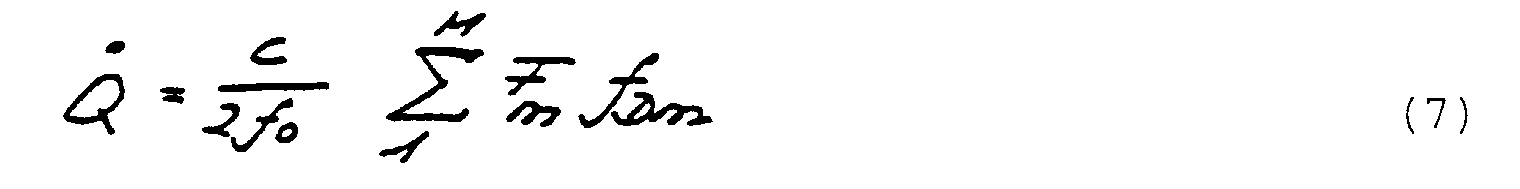
- Fm :
- Fläche des auf die Messebene projizierten Volumenelementes, Messebene senkrecht zur Beschallungsrichtung
- c :
- Schallgeschwidigkeit
- fo :
- Frequenz von r(t)
- fDm :
- Dopplerfrequenz im m-ten Volumenelement
Claims (17)
- Verfahren zum Messen des Volumenstromes in einer Schicht (4) mit reflektierender Struktur eines Materialvolumens, mittels Auswertung von Schall- oder Ultraschallecho (enm), dadurch gekennzeichnet, dassmindestens zwei Sende-Wellenpakete (S' (t)) zeitgestaffelt erzeugt werden,eine Mehrzahl Schall- oder Ultraschallsensoren (1) in einer mindestens eindimensionalen Anordnung (1a) vorgesehen wird,der Schicht (4) ein Muster von Volumenelementen (4a) zugeordnet wird, wobei mindestens die Distanz (rnm) jedes Sensors (1) von jedem Volumenelement (4a) bekannt bzw. vorgegeben ist,für jedes Sende-Wellenpaket:für jeden Sensor (1) die Echo-Empfangszeit (tnma) von jedem Volumenelement (4a) bestimmt wird,damit aus dem an jedem Sensor (1) empfangenen Echo Volumenelementechos (Σc*nm) selektioniert werden,die Volumenelementechos (Σc*nm) jedes einzelnen Volumenelementes (4a) über alle Sensoren (1) miteinander verrechnet werden, zum Erhalt eines Gesamt-Volumenelementechos (Cm) von jedem Volumenelement (4a), das repräsentativ ist für die reflektierende Struktur im einzelnen Volumenelement,durch Auswerten der Phase (17) der Gesamt-Volumenelementechowellen (Δϕ(Cm, C'm)) ein zur Geschwindigkeit der Struktur in den Volumenelementen (4a) proportionales Volumenelement-Geschwindigkeitssignal (vm) gebildet wird unddurch gegebenenfalls gewichtete Summation der Volumenelement-Geschwindigkeitsignale (vm) der Volumenstrom (Q ˙) durch die Schicht bestimmt wird.
- Verfahren nach Anspruch 1, dadurch gekennzeichnet, dass das Sende-Wellenpaket (s'(t)) so erzeugt wird, dass es die Schicht (4) mindestens genähert kohärent, d.h. mindestens genähert phasengleich, erreicht.
- Verfahren nach einem der Ansprüche 1 oder 2, dadurch gekennzeichnet, dass die Sende-Wellenpakete (S' (t)) durch zeit- und phasenrichtige Anregung (s(t)) einer Mehrzahl von Schall- oder Ultraschallquellen (1) erzeugt werden.
- Verfahren nach einem der Ansprüche 1 bis 3, dadurch gekennzeichnet, dass die Sende-Wellenpakete (s'(t)) durch mindestens genähert gleichzeitige Anregung einer Mehrzahl mindestens genähert in einer Ebene (1a) angeordneter Schall- oder Ultraschallquellen (1) erzeugt werden.
- Verfahren nach einem der Ansprüche 1 bis 4, dadurch gekennzeichnet, dass die Sensoren (1) matrixförmig (1a), mindestens genähert in einer Ebene angeordnet werden.
- Verfahren nach einem der Ansprüche 1 bis 5, dadurch gekennzeichnet, dass Quellen (1) zur Erzeugung der Sende-Wellenpakete (s'(t)) und die Sensoren (1) mittels einer räumlichen Anordnung von Sende- und Empfangstransducern (1) gebildet werden, vorzugsweise einer mindestens genähert ebenen (1a).
- Verfahren nach einem der Ansprüche 1 bis 6, dadurch gekennzeichnet, dass die Sende-Wellenpakete (s'(t)) mittels einer Mehrzahl Schall- oder Ultraschallquellen (1) erzeugt werden, die je von einem, von einem stabilen, vorzugsweise quarzstabilen Referenzsignal (r(t)) mindestens abgeleiteten Anregungssignal angeregt werden.
- Verfahren nach Anspruch 7, dadurch gekennzeichnet, dass das Referenzsignal (r(t)) zur Demodulation des Echos, vorzugsweise zur Demodulation je der von den Sensoren (1) gewandelten Echos eingesetzt wird.
- Verfahren nach einem der Ansprüche 1 bis 8, dadurch gekennzeichnet, dass die Echos von jedem Sensor (1) digitalisiert (10) und gespeichert (12) werden, vorzugsweise nach deren Demodulation (8).
- Verfahren nach einem der Ansprüche 1 bis 9, dadurch gekennzeichnet, dass die Echos von jedem Sensor (1) digitalisiert werden, die unterschiedlichen Laufzeiten, entsprechend unterschiedlichen Echo-Empfangszeiten von Volumenelementechos, an allen Sensoren (1) durch entsprechende rechnerische Phasendrehung (tnma) kompensiert werden, derart, dass von allen Sensoren (1) gleichphasige, laufzeitkompensierte Volumenelement-Echosignale (Σc*nm) vorliegen.
- Verfahren nach einem der Ansprüche 1 bis 10, dadurch gekennzeichnet, dass die Verrechnung der Echos aller Sensoren (1) so erfolgt, dass dabei das Echo eines jeweiligen Volumenelementes (m) verstärkt wird, gegenüber Echos von allen anderen Volumenelementen.
- Verfahren nach Anspruch 11, dadurch gekennzeichnet, dass die laufzeitkompensierten Volumenelement-Echosignale (Σc*nm), wie durch Superposition (15) miteinander verrechnet werden und durch diese Korrelations-Verrechnung von anderen Volumenelementen stammende Volumenelementechos unterdrückt werden.
- Verfahren nach Anspruch 9, dadurch gekennzeichnet, dass die gespeicherten (12) Echos je von allen Sensoren (1) als Datenbasis für die Verrechnung zum Erhalt der Gesamt-Volumenelementechos (Cm) aller Volumenelemente (4a) eingesetzt werden.
- Messanordnung zum Messen des Volumenstromes (Q ˙) in einer Schicht (4) mit reflektierender Struktur durch ein Materialvolumen, mittels Auswertung von Schall- oder Ultraschallecho, dadurch gekennzeichnet, dass vorgesehen sind:und dasseine Senderanordnung (1, 1a) zur Beschallung des Materialvolumens,eine Anordnung räumlich verteilter Empfangssensoren (1),jedem Sensor (1) nachgeschaltet:eine Digitalisierungs- und eine gemeinsame Korrelationsanordnung (12, 12a, 13, 14, 15) zur Digitalisierung und zur Strukturierung des von den Empfangssensoren empfangenen Echos,der Senderanordnung (1) eine Anregungseinheit (6) zugeschaltet ist, die die Senderanordnung zur Abgabe mindestens von zwei zeitlich getrennten Sende-Wellenpaketen (s'(t)) anregt undein Frequenz- bzw. Phasendetektor (17) vorgesehen ist, um auf der Basis des Doppler-Effektes die Strukturgeschwindigkeit in der Schicht zu berechnen, weiterdem Phasen- bzw. Frequenzdetektor (17) ein Summator (18) nachgeschaltet ist, um aus den Geschwindigkeitssignalen den Volumenstrom durch die Schicht zu berechnen.
- Messanordnung nach Anspruch 14, dadurch gekennzeichnet, dass die Korrelationsanordnung einen Summator (15) umfasst, dem alle Empfangssensoren vorgeschaltet sind.
- Messanordnung nach Anspruch 15, dadurch gekennzeichnet, dass den Digitalisierungsanordnungen und dem Summator (15) ein Interpolator (13) zwischengeschaltet ist.
- Messanordnung nach einem der Ansprüche 15 oder 16, dadurch gekennzeichnet, dass dem Summator (15) der Korrelationsanordnung ein Speicher (16) nachgeschaltet ist, worin die Summator-Ausgangsdaten für jedes Sende-Wellenpaket gespeichert werden, und dass der Frequenz- bzw. Phasendetektor (17) dem Speicher (16) nachgeschaltet ist, um aus den Summator-Ausgangsdaten für die Wellenpakete die Strukturgeschwindigkeit in der Schicht (4) zu berechnen.
Applications Claiming Priority (3)
| Application Number | Priority Date | Filing Date | Title |
|---|---|---|---|
| CH3886/88 | 1988-10-19 | ||
| CH388688 | 1988-10-19 | ||
| EP89912415A EP0394428B1 (de) | 1988-10-19 | 1989-10-19 | Verfahren und vorrichtung zum messen von zweidimensionalen reflektierenden strukturen |
Related Parent Applications (2)
| Application Number | Title | Priority Date | Filing Date |
|---|---|---|---|
| EP89912415.0 Division | 1989-10-19 | ||
| EP89912415A Division EP0394428B1 (de) | 1988-10-19 | 1989-10-19 | Verfahren und vorrichtung zum messen von zweidimensionalen reflektierenden strukturen |
Publications (3)
| Publication Number | Publication Date |
|---|---|
| EP0616231A2 EP0616231A2 (de) | 1994-09-21 |
| EP0616231A3 EP0616231A3 (de) | 1994-10-12 |
| EP0616231B1 true EP0616231B1 (de) | 1998-03-04 |
Family
ID=4265622
Family Applications (2)
| Application Number | Title | Priority Date | Filing Date |
|---|---|---|---|
| EP89912415A Expired - Lifetime EP0394428B1 (de) | 1988-10-19 | 1989-10-19 | Verfahren und vorrichtung zum messen von zweidimensionalen reflektierenden strukturen |
| EP94109331A Expired - Lifetime EP0616231B1 (de) | 1988-10-19 | 1989-10-19 | Verfahren und Messanordnung zum Messen des Volumenstromes in einer Schicht mit reflektierender Struktur |
Family Applications Before (1)
| Application Number | Title | Priority Date | Filing Date |
|---|---|---|---|
| EP89912415A Expired - Lifetime EP0394428B1 (de) | 1988-10-19 | 1989-10-19 | Verfahren und vorrichtung zum messen von zweidimensionalen reflektierenden strukturen |
Country Status (5)
| Country | Link |
|---|---|
| US (1) | US5117692A (de) |
| EP (2) | EP0394428B1 (de) |
| AT (2) | ATE118897T1 (de) |
| DE (2) | DE58909035D1 (de) |
| WO (1) | WO1990004793A1 (de) |
Families Citing this family (5)
| Publication number | Priority date | Publication date | Assignee | Title |
|---|---|---|---|---|
| DE4310390C2 (de) * | 1993-03-30 | 1995-03-16 | Topping Best Ltd | Ultraschallabbildungsvorrichtung zur Erfassung und/oder Identifikation von Oberflächenstrukturen und oberflächennahen Strukturen |
| US5808967A (en) * | 1996-10-07 | 1998-09-15 | Rowe-Deines Instruments Incorporated | Two-dimensional array transducer and beamformer |
| AU4393300A (en) | 1999-05-10 | 2000-11-21 | B-K Medical A/S | Vector velocity estimation using directional beam forming and cross-correlation |
| US20200191928A1 (en) * | 2017-04-24 | 2020-06-18 | Koninklijke Philips N.V. | Systems and methods for beamforning ultrasound signals using elastic interpolation |
| CN114895065B (zh) * | 2022-04-11 | 2025-05-13 | 上海理工大学 | 一种斜口空耦超声换能器测量狭窄流道气流速度场的方法 |
Family Cites Families (8)
| Publication number | Priority date | Publication date | Assignee | Title |
|---|---|---|---|---|
| US4097835A (en) * | 1976-09-20 | 1978-06-27 | Sri International | Dual transducer arrangement for ultrasonic imaging system |
| US4596145A (en) * | 1983-09-20 | 1986-06-24 | Smith Stephen W | Acoustic orthoscopic imaging system |
| US4530363A (en) * | 1983-10-20 | 1985-07-23 | General Electric Company | Transducer array for sector scan and doppler flow measurement applications |
| JPH0614930B2 (ja) * | 1985-02-19 | 1994-03-02 | 株式会社日立メデイコ | 超音波診断装置 |
| US4608868A (en) * | 1985-03-22 | 1986-09-02 | Sri International | Ultrasonic reflex transmission imaging method and apparatus |
| US4831601A (en) * | 1986-10-31 | 1989-05-16 | Siemens Aktiengesellschaft | Apparatus for transmitting and receiving ultrasonic signals |
| US4835689A (en) * | 1987-09-21 | 1989-05-30 | General Electric Company | Adaptive coherent energy beam formation using phase conjugation |
| US4800891A (en) * | 1987-11-13 | 1989-01-31 | Siemens Medical Laboratories, Inc. | Doppler velocity processing method and apparatus |
-
1989
- 1989-10-19 AT AT89912415T patent/ATE118897T1/de not_active IP Right Cessation
- 1989-10-19 DE DE58909035T patent/DE58909035D1/de not_active Expired - Fee Related
- 1989-10-19 EP EP89912415A patent/EP0394428B1/de not_active Expired - Lifetime
- 1989-10-19 DE DE58909833T patent/DE58909833D1/de not_active Expired - Fee Related
- 1989-10-19 WO PCT/EP1989/001246 patent/WO1990004793A1/de not_active Ceased
- 1989-10-19 AT AT94109331T patent/ATE163770T1/de not_active IP Right Cessation
- 1989-10-19 US US07/499,412 patent/US5117692A/en not_active Expired - Fee Related
- 1989-10-19 EP EP94109331A patent/EP0616231B1/de not_active Expired - Lifetime
Also Published As
| Publication number | Publication date |
|---|---|
| ATE118897T1 (de) | 1995-03-15 |
| EP0394428B1 (de) | 1995-02-22 |
| WO1990004793A1 (de) | 1990-05-03 |
| DE58909833D1 (de) | 1998-04-09 |
| US5117692A (en) | 1992-06-02 |
| EP0616231A2 (de) | 1994-09-21 |
| DE58909035D1 (de) | 1995-03-30 |
| ATE163770T1 (de) | 1998-03-15 |
| EP0394428A1 (de) | 1990-10-31 |
| EP0616231A3 (de) | 1994-10-12 |
Similar Documents
| Publication | Publication Date | Title |
|---|---|---|
| DE19912089B4 (de) | Verfahren und Einrichtung zur Farbfluß-Bildgebung unter Verwendung von Golay-codierter Anregung beim Senden und Pulskomprimierung beim Empfangen | |
| EP1194920B1 (de) | Rekursive ultraschallabbildung | |
| DE69710725T2 (de) | Vorrichtung zur bestimmung von bewegungen und geschwindigkeiten sich bewegender objekte | |
| EP0043158B1 (de) | Ultraschall-Untersuchungsanordnung | |
| US4265126A (en) | Measurement of true blood velocity by an ultrasound system | |
| EP0337293A1 (de) | Füllstandsmessgerät | |
| EP0987563A2 (de) | Verfahren zur Bestimmung des Abstandes zwischen einem Objekt und einer sich örtlich verändernden Einrichtung, insbesondere einem Kraftfahrzeug | |
| DE102009042968A1 (de) | Verfahren und Vorrichtung zum Vermessen eines Bodenprofils | |
| CA1250042A (en) | Ultrasonic reflex transmission imaging method and apparatus | |
| EP0814348A2 (de) | Messverfahren für den Abstand zwischen einem Kraftfahrzeug und einem Objekt | |
| DE19909699A1 (de) | Verfahren und Anordnung für eine gepulste Dopplerbildgebung unter Anwendung einer kodierten Anregung beim Senden und einer Pulskompression beim Empfangen | |
| JP4502417B2 (ja) | スペクトル広がりエラー・マージンを表示する方法およびシステム | |
| EP0616231B1 (de) | Verfahren und Messanordnung zum Messen des Volumenstromes in einer Schicht mit reflektierender Struktur | |
| DE69117345T2 (de) | Mess- und Anzeigevorrichtung für die Geschwindigkeit der Blutströmung mittels Ultraschallechographie | |
| DE69839062T2 (de) | Vorrichtung zur ultraschall-diagnose | |
| DE3828398C2 (de) | Doppler-Meßgerät | |
| EP0138017A1 (de) | Verfahren zur Ultraschall-Durchflussmessung nach dem Dopplerprinzip mit verbesserter Ortsauflösung | |
| DE69515444T2 (de) | Verfahren zum Entdecken von Gegenständen in der Bodenfläche oder zum Bestimmen der Ausbreitungsmerkmale einer akustischen Welle im Boden und Vorrichtung dafür | |
| DE19934212B4 (de) | Verfahren und Vorrichtung zum Messen der Strömungsgeschwindigkeit eines Fluidstromes | |
| DE69106209T2 (de) | Aufsichtsvorrichtung. | |
| DE69717908T2 (de) | Dauerstrichultraschalldopplerblutströmungsmesser | |
| EP0335578A2 (de) | Ultraschall-Abbildungssystem mit zwei oder mehreren gleichzeitig aktiven Aperturen | |
| DE3715914C2 (de) | ||
| DE10318756B4 (de) | Verfahren und Vorrichtung zur Bestimmung der Dicke von Blattgut | |
| DE4206570C2 (de) | Ultraschall-Geschwindigkeitsmesser |
Legal Events
| Date | Code | Title | Description |
|---|---|---|---|
| PUAI | Public reference made under article 153(3) epc to a published international application that has entered the european phase |
Free format text: ORIGINAL CODE: 0009012 |
|
| PUAL | Search report despatched |
Free format text: ORIGINAL CODE: 0009013 |
|
| AC | Divisional application: reference to earlier application |
Ref document number: 394428 Country of ref document: EP |
|
| AK | Designated contracting states |
Kind code of ref document: A2 Designated state(s): AT BE CH DE FR GB IT LI LU NL SE |
|
| AK | Designated contracting states |
Kind code of ref document: A3 Designated state(s): AT BE CH DE FR GB IT LI LU NL SE |
|
| 17P | Request for examination filed |
Effective date: 19941107 |
|
| GRAG | Despatch of communication of intention to grant |
Free format text: ORIGINAL CODE: EPIDOS AGRA |
|
| 17Q | First examination report despatched |
Effective date: 19961030 |
|
| GRAG | Despatch of communication of intention to grant |
Free format text: ORIGINAL CODE: EPIDOS AGRA |
|
| GRAH | Despatch of communication of intention to grant a patent |
Free format text: ORIGINAL CODE: EPIDOS IGRA |
|
| GRAH | Despatch of communication of intention to grant a patent |
Free format text: ORIGINAL CODE: EPIDOS IGRA |
|
| GRAA | (expected) grant |
Free format text: ORIGINAL CODE: 0009210 |
|
| AC | Divisional application: reference to earlier application |
Ref document number: 394428 Country of ref document: EP |
|
| AK | Designated contracting states |
Kind code of ref document: B1 Designated state(s): AT BE CH DE FR GB IT LI LU NL SE |
|
| PG25 | Lapsed in a contracting state [announced via postgrant information from national office to epo] |
Ref country code: NL Free format text: LAPSE BECAUSE OF FAILURE TO SUBMIT A TRANSLATION OF THE DESCRIPTION OR TO PAY THE FEE WITHIN THE PRESCRIBED TIME-LIMIT Effective date: 19980304 Ref country code: IT Free format text: LAPSE BECAUSE OF FAILURE TO SUBMIT A TRANSLATION OF THE DESCRIPTION OR TO PAY THE FEE WITHIN THE PRE;WARNING: LAPSES OF ITALIAN PATENTS WITH EFFECTIVE DATE BEFORE 2007 MAY HAVE OCCURRED AT ANY TIME BEFORE 2007. THE CORRECT EFFECTIVE DATE MAY BE DIFFERENT FROM THE ONE RECORDED.SCRIBED TIME-LIMIT Effective date: 19980304 Ref country code: GB Free format text: LAPSE BECAUSE OF FAILURE TO SUBMIT A TRANSLATION OF THE DESCRIPTION OR TO PAY THE FEE WITHIN THE PRESCRIBED TIME-LIMIT Effective date: 19980304 Ref country code: FR Free format text: LAPSE BECAUSE OF FAILURE TO SUBMIT A TRANSLATION OF THE DESCRIPTION OR TO PAY THE FEE WITHIN THE PRESCRIBED TIME-LIMIT Effective date: 19980304 |
|
| REF | Corresponds to: |
Ref document number: 163770 Country of ref document: AT Date of ref document: 19980315 Kind code of ref document: T |
|
| REG | Reference to a national code |
Ref country code: CH Ref legal event code: NV Representative=s name: TROESCH SCHEIDEGGER WERNER AG Ref country code: CH Ref legal event code: EP |
|
| REF | Corresponds to: |
Ref document number: 58909833 Country of ref document: DE Date of ref document: 19980409 |
|
| PG25 | Lapsed in a contracting state [announced via postgrant information from national office to epo] |
Ref country code: SE Free format text: LAPSE BECAUSE OF FAILURE TO SUBMIT A TRANSLATION OF THE DESCRIPTION OR TO PAY THE FEE WITHIN THE PRESCRIBED TIME-LIMIT Effective date: 19980604 |
|
| EN | Fr: translation not filed | ||
| NLV1 | Nl: lapsed or annulled due to failure to fulfill the requirements of art. 29p and 29m of the patents act | ||
| GBV | Gb: ep patent (uk) treated as always having been void in accordance with gb section 77(7)/1977 [no translation filed] |
Effective date: 19980304 |
|
| PG25 | Lapsed in a contracting state [announced via postgrant information from national office to epo] |
Ref country code: LU Free format text: LAPSE BECAUSE OF NON-PAYMENT OF DUE FEES Effective date: 19981019 Ref country code: AT Free format text: LAPSE BECAUSE OF NON-PAYMENT OF DUE FEES Effective date: 19981019 |
|
| PG25 | Lapsed in a contracting state [announced via postgrant information from national office to epo] |
Ref country code: BE Free format text: LAPSE BECAUSE OF NON-PAYMENT OF DUE FEES Effective date: 19981031 |
|
| PLBE | No opposition filed within time limit |
Free format text: ORIGINAL CODE: 0009261 |
|
| STAA | Information on the status of an ep patent application or granted ep patent |
Free format text: STATUS: NO OPPOSITION FILED WITHIN TIME LIMIT |
|
| 26N | No opposition filed | ||
| BERE | Be: lapsed |
Owner name: INSTITUT FUR BIOMEDIZINISCHE TECHNIK UND MEDIZINI Effective date: 19981031 |
|
| PGFP | Annual fee paid to national office [announced via postgrant information from national office to epo] |
Ref country code: DE Payment date: 20001118 Year of fee payment: 12 |
|
| PGFP | Annual fee paid to national office [announced via postgrant information from national office to epo] |
Ref country code: CH Payment date: 20010111 Year of fee payment: 12 |
|
| PG25 | Lapsed in a contracting state [announced via postgrant information from national office to epo] |
Ref country code: LI Free format text: LAPSE BECAUSE OF NON-PAYMENT OF DUE FEES Effective date: 20011031 Ref country code: CH Free format text: LAPSE BECAUSE OF NON-PAYMENT OF DUE FEES Effective date: 20011031 |
|
| REG | Reference to a national code |
Ref country code: CH Ref legal event code: PL |
|
| PG25 | Lapsed in a contracting state [announced via postgrant information from national office to epo] |
Ref country code: DE Free format text: LAPSE BECAUSE OF NON-PAYMENT OF DUE FEES Effective date: 20020702 |