EP0616347A1 - Disjoncteur uni- ou multipolaire - Google Patents
Disjoncteur uni- ou multipolaire Download PDFInfo
- Publication number
- EP0616347A1 EP0616347A1 EP94101023A EP94101023A EP0616347A1 EP 0616347 A1 EP0616347 A1 EP 0616347A1 EP 94101023 A EP94101023 A EP 94101023A EP 94101023 A EP94101023 A EP 94101023A EP 0616347 A1 EP0616347 A1 EP 0616347A1
- Authority
- EP
- European Patent Office
- Prior art keywords
- circuit breaker
- housing
- shell
- breaker according
- row direction
- Prior art date
- Legal status (The legal status is an assumption and is not a legal conclusion. Google has not performed a legal analysis and makes no representation as to the accuracy of the status listed.)
- Granted
Links
- 230000005405 multipole Effects 0.000 title claims abstract description 5
- 230000008878 coupling Effects 0.000 claims abstract description 71
- 238000010168 coupling process Methods 0.000 claims abstract description 71
- 238000005859 coupling reaction Methods 0.000 claims abstract description 71
- 230000007246 mechanism Effects 0.000 claims abstract description 31
- 230000000149 penetrating effect Effects 0.000 claims 2
- 210000000629 knee joint Anatomy 0.000 claims 1
- 238000004519 manufacturing process Methods 0.000 description 19
- 230000005540 biological transmission Effects 0.000 description 5
- 238000005516 engineering process Methods 0.000 description 4
- 230000000694 effects Effects 0.000 description 3
- 230000001960 triggered effect Effects 0.000 description 2
- 230000001154 acute effect Effects 0.000 description 1
- 239000003795 chemical substances by application Substances 0.000 description 1
- 238000010276 construction Methods 0.000 description 1
- 230000001419 dependent effect Effects 0.000 description 1
- 239000000834 fixative Substances 0.000 description 1
- 238000010438 heat treatment Methods 0.000 description 1
- 230000001771 impaired effect Effects 0.000 description 1
- 238000009434 installation Methods 0.000 description 1
- 230000007257 malfunction Effects 0.000 description 1
- 238000000034 method Methods 0.000 description 1
- 238000005192 partition Methods 0.000 description 1
- 230000003716 rejuvenation Effects 0.000 description 1
- IHQKEDIOMGYHEB-UHFFFAOYSA-M sodium dimethylarsinate Chemical class [Na+].C[As](C)([O-])=O IHQKEDIOMGYHEB-UHFFFAOYSA-M 0.000 description 1
Images


Classifications
-
- H—ELECTRICITY
- H01—ELECTRIC ELEMENTS
- H01H—ELECTRIC SWITCHES; RELAYS; SELECTORS; EMERGENCY PROTECTIVE DEVICES
- H01H71/00—Details of the protective switches or relays covered by groups H01H73/00 - H01H83/00
- H01H71/02—Housings; Casings; Bases; Mountings
-
- H—ELECTRICITY
- H01—ELECTRIC ELEMENTS
- H01H—ELECTRIC SWITCHES; RELAYS; SELECTORS; EMERGENCY PROTECTIVE DEVICES
- H01H71/00—Details of the protective switches or relays covered by groups H01H73/00 - H01H83/00
- H01H71/02—Housings; Casings; Bases; Mountings
- H01H71/0207—Mounting or assembling the different parts of the circuit breaker
-
- H—ELECTRICITY
- H01—ELECTRIC ELEMENTS
- H01H—ELECTRIC SWITCHES; RELAYS; SELECTORS; EMERGENCY PROTECTIVE DEVICES
- H01H71/00—Details of the protective switches or relays covered by groups H01H73/00 - H01H83/00
- H01H71/10—Operating or release mechanisms
- H01H71/1009—Interconnected mechanisms
-
- H—ELECTRICITY
- H01—ELECTRIC ELEMENTS
- H01H—ELECTRIC SWITCHES; RELAYS; SELECTORS; EMERGENCY PROTECTIVE DEVICES
- H01H73/00—Protective overload circuit-breaking switches in which excess current opens the contacts by automatic release of mechanical energy stored by previous operation of a hand reset mechanism
- H01H73/22—Protective overload circuit-breaking switches in which excess current opens the contacts by automatic release of mechanical energy stored by previous operation of a hand reset mechanism having electrothermal release and no other automatic release
- H01H73/26—Protective overload circuit-breaking switches in which excess current opens the contacts by automatic release of mechanical energy stored by previous operation of a hand reset mechanism having electrothermal release and no other automatic release reset by tumbler
Definitions
- the invention relates to a circuit breaker with the features of the preamble of claim 1.
- Such a circuit breaker is known from EP-B-0 208 613 .
- the switch housing of the circuit breaker disclosed there has two outer shells, namely a housing shell and an end shell which can be placed thereon.
- the switching mechanism is arranged between the two shells.
- the circuit breaker can be tripped free in the event of overcurrent, for example, by means of a bimetal connected to the switching mechanism.
- the single-pole circuit breaker with the pole chamber formed between the housing shell and the end shell can be expanded to a multi-pole circuit breaker with a corresponding number of pole chambers.
- one or more intermediate housing shells of identical design are inserted between the housing shell and the end shell.
- the section of the intermediate housing shell facing the housing shell corresponds structurally to the end shell.
- the intermediate housing shell is therefore placed on the housing shell in the same way as the end shell.
- the section of the intermediate housing shell facing the end shell corresponds structurally to the housing shell. In this way, the single-pole circuit breaker can be expanded to a circuit breaker with any number of poles.
- the same switching mechanism is located in each pole chamber. So that a common triggering of all poles of the circuit breaker is possible, identical switching levers, which effect the opening and closing of the electrical contacts, are coupled to all the pole chambers.
- the coupling parts are cylindrical bolts formed on the shift levers with a longitudinal axis running perpendicular to the shell plane.
- a shaft-like bolt is mounted on the shells in each pole chamber.
- each bolt is affected by its own torsional moments.
- the torsional moments additionally reduce the transmitted torque.
- the shells of the circuit breaker are structurally very complex to enable the bolts to rotate properly.
- the diameter of the bearing bore or the size of the bearing clearance must be taken into account. Due to the manufacturing-related influences, however, the desired storage is not always guaranteed.
- the risk of the bolt being misaligned with respect to its bearing bore is very great. This effect increases according to the number of poles of the circuit breaker. This further reduces the torque transmitted. In extreme cases, the misalignment even leads to a blockage of the bolt. In addition, skewed bolts can damage the shells. The heating within the pole chambers leads to deformations of the bearing bores, so that the bearing of the bolts is further impaired.
- the invention has for its object to further improve such a circuit breaker. This object is achieved by the combination of features of claim 1.
- each shift lever is axially supported on the housing side.
- the rotary movement of the shift lever therefore only counteracts a constant low frictional force regardless of the number of poles due to the axle bearing.
- Such storage prevents the transmission of frictional forces on adjacent shift levers.
- the coupling rod thereby enables a uniform transmission of the rotary movement of the immediately triggering shift lever to the other shift lever even with a larger number of poles.
- the common tripping of all poles of the circuit breaker is therefore guaranteed.
- the operational safety of the circuit breaker is further improved.
- the coupling of the switching levers according to the invention further has the effect that slight manufacturing-related inaccuracies in the manufacture of the shells of the circuit breaker do not impair the transmission of the rotary movements. This greatly reduces the proportion of rejects in the manufacture of the shells. This in turn reduces the manufacturing cost of the entire circuit breaker.
- the bearings of the shift lever can be produced with little effort and support the cost-effective production of the shells.
- the coupling of the switching levers is easy to manufacture in terms of assembly technology and therefore also reduces costs in the manufacture of the circuit breaker.
- the coupling takes place in a single operation, in which the coupling rod is simply pushed through the intermediate housing shells and the shift lever in the row direction immediately before the end shell is attached.
- the shift lever act as a closed bearing for the coupling rod. This supports the even transmission of power to all gear levers.
- the small amount of slack between the coupling rod and its bearing ensures that there is little freedom of movement for the coupling rod.
- the lots also take production-related dimensional tolerances into account when aligning all switch levers in the row direction of the circuit breaker. This also keeps the proportion of rejects in the manufacture of the components of the circuit breaker low. Furthermore, the loose additionally simplifies the assembly of the coupling rod.
- Claim 3 takes into account the simple manufacture of a through recess for the coupling rod.
- the coupling rod itself can also be simply manufactured as a cylindrical rod in terms of production technology.
- other cross-sectional shapes of coupling rods with corresponding passage recesses are also conceivable.
- the coupling rod is adapted in terms of its length to the number of poles and to the pole chamber width of the circuit breaker in such a way that it affects the housing shell and the end shell in the final assembly state of the circuit breaker with a small distance.
- the coupling rod is secured against inadvertent shifting movements in the row direction. All switch levers therefore remain reliably coupled to one another when the circuit breaker is in the final assembly state.
- the coupling rod affects a correspondingly shaped recess in the intermediate housing shell.
- the switching movements of the shift levers are also performed. Malfunctions of the shift levers are excluded.
- the rod recess surrounds the movement path of the coupling rod with a small distance, so that deviations in the movement path due to production are also taken into account.
- Claim 7 further supports the assembly-friendly assembly of the circuit breaker. Due to their design, the shells of the circuit breaker have several functions. For example, they act as boundary walls for the pole chambers, as a fixing means for the switching mechanism and also as a housing shaft for a switching element acting on the switching mechanism. Since the most diverse functions are implemented with a few, one-piece components, the entire mechanism of the circuit breaker is less prone to failure.
- the one-piece production of various functional areas of the shells according to claim 7 and 8 also ensures a mechanically very stable structure of the circuit breaker.
- Claim 10 takes into account in the manufacture of the switching element the cross-section of the housing shaft, which is dependent on the number of poles, for receiving the switching element.
- the housing shaft can therefore also act as a guide element for guiding the switching movements of the switching element.
- a switching element adapted to the cross section of the housing shaft acts as reliable protection against damage and as electrical hazard protection for all pole chambers of the circuit breaker. In addition, such a switching element enables convenient manual operation even with circuit breakers with a larger number of poles.
- the switching element relieves the coupling rod.
- One actor is assigned to one switching mechanism. When the circuit breaker is triggered manually, the switch levers are therefore acted upon directly by the effective end of the switching element and not only via the detour of a single switch lever and the coupling rod. According to claims 12 and 13, the switching element is simply mounted in terms of assembly technology.
- the switching element can be additionally supported on this intermediate housing shell with a corresponding structural design according to claims 14 and 15, so that the mechanical stability of the pivot bearing of the switching element is ensured or improved even with a large number of poles.
- the switching element is pivotally mounted only on some of the overall housing intermediate shells.
- Claims 16 to 18 relate to the application of the coupling between switching element and switching mechanism known from DE 27 21 162 A1 with all its advantages to the circuit breaker according to the invention.
- the switching element and the switching mechanism are coupled to one another via a cam rod running in the row direction.
- Claims 17 and 18 apply the coupling of all identical shift levers according to the invention to the cam rod by means of the coupling rod at.
- the switching element acts in a reliable manner on all switching mechanisms of the circuit breaker in a reliable manner with little effort.
- a frame that can be easily mounted on the shells is provided as a mechanical damage protection element for the switching element.
- the cover frame has the further function as a fixing means for the shells in the final assembly state of the circuit breaker.
- a further fixing means is provided to further improve the mechanically stable structure of the circuit breaker housing. Since the fixing means penetrates all the shells of the switch housing, it can also serve as an assembly aid for the loose lining up of all shells during assembly.
- Claim 23 proposes a fixative that is easy to manufacture and assemble. Since, on the one hand, the fixing means is arranged in the region of the housing base and, on the other hand, the cover frame fixes the shells in the region of the housing shaft, the switch housing, which is constructed from several shells, acts as a compact unit in the final assembly state. By releasing the cover frame or the fixing agent, the circuit breaker can be disassembled in a modular manner if necessary and therefore easy to assemble.
- An arrangement of the rods according to claim 24 takes into account their simple assembly with a small space requirement within the pole chambers.
- Claim 26 takes into account the structure of the circuit breaker with little space. In addition, the same level of movement allows the different Lever and the rods a very effective power transmission between the components within the pole chambers.
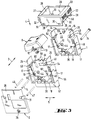
- the housing of the single-pole circuit breaker shown in FIG. 1 essentially consists of a housing shell 1 and an end shell 2 oriented parallel to it. Both shells 1, 2 are displaced in a row direction 3 and are directly fixed to one another in the final assembly state with their mutually facing surfaces .
- the row direction 3 is arranged at right angles to the shell plane in which the two shells 1, 2 lie.
- the shell plane is spanned by a mounting direction 4 and a transverse direction 5. All directions 3, 4, 5 are arranged at right angles to one another.
- the plane spanned by the mounting direction 4 and the transverse direction 5 corresponds to the plane of movement of the switching mechanism of the circuit breaker.
- the switching mechanism consists essentially of a release lever 6, a latching lever 7 and a rocker switch 8 for manually switching the circuit breaker on and off.
- a bimetal 9 running in the transverse direction 5 acts on the release lever 6 in the event of an overcurrent, thereby causing the circuit breaker to trip.
- the release lever 6 is pivotally mounted on a cylindrical journal 10 extending in the row direction 3.
- the rocker switch 8 is pivotally mounted on an axle pin 11. Both axle journals 10, 11 are formed on the inside of the housing shell 1 and arranged parallel to one another. However, the journal 10 extends further in the direction of the end shell 2.
- the switching rocker 8 surrounds the axle pin 11 in the final assembly state with an axle bore passing through it in the row direction 3.
- the corresponding hole in the release lever for its pivot mounting on the axle pin 10 is not visible in FIG. 1.
- an active end 13 with an outline shape which tapers approximately conically in the direction of the shift lever 7 is integrally formed on the rocker switch 8.
- the cone tip of the effective end 13 facing the latching lever 7 is rounded off like a segment of a circle.
- the effective end 13 has a bore running in the row direction 3, which is penetrated by a cylindrical cam rod 14 in the final assembly state.
- the cam rod 14 In the final assembly state, the cam rod 14 also passes through an approximately V-shaped cam path 15 of the shift lever 7. During the switching movement of the rocker switch 8, the cam rod 14 runs on the cam path 15.
- the two axle journals 10, 11 are integrally formed on the inside of a housing wall 16 forming part of the housing shell 1.
- the housing wall 16 lies in the plane spanned by the mounting direction 4 and the transverse direction 5.
- the edge edges of the housing wall 16 extending in the mounting direction are each integrally connected to a housing side wall 17.
- the housing side walls 17 are arranged at right angles to the housing wall 16. When viewed in mounting direction 4, this results in a U-shape of housing shell 1.
- a U-shaped outline contour of housing shell 1 is also produced are connected in one piece.
- the housing base 18 lies in a plane spanned by the row direction 3 and the transverse direction 5.
- a further recess in the housing base serves to accommodate a cylindrical bolt which runs with its longitudinal axis in the direction of attachment 4 and acts as an adjusting screw 22 for adjusting the bimetal 9.
- the housing wall 16, the housing side walls 17 and the housing base 18 on the part of the housing shell 1 delimit a cavity 23 of the circuit breaker housing which acts as a pole chamber.
- the cavity 23 is closed in the assembled state of the circuit breaker in the row direction 3 on the part of the end shell 2.
- the edge regions of the end shell 2 lying in the shell plane, which extend in the mounting direction 4, are bent in the row direction 3 and, in the final assembly state, lie directly against the edge edges of the housing side walls 17 facing them.
- the cavity 23 is accessible through a housing opening opposite the housing base 18 against the mounting direction 4.
- This housing opening is delimited by a rectangular housing shaft 24.
- the housing shaft 24 consists of the free ends 25 of the housing side walls 17, the partial area of the housing wall 16 connecting the two free ends 25 and a free end 26 as part of the end shell 2.
- the approximately end-to-end rectangular end 26 is row-like compared to the rest of the end shell 2 rejuvenated.
- the extension of the free end 26 in the transverse direction 5 corresponds to the distance in the transverse direction 5 between the two free ends 25. Accordingly, the two free ends 25 are arranged offset in the transverse direction 5 with respect to the rest of the housing side walls 17, so that the housing shaft 24 has a smaller cross section than that area of the circuit breaker housing facing the housing base 18.
- the housing shaft 24 surrounds the partial area of the rocker switch 8 facing the latching lever 7.
- the housing shaft 24 is in turn surrounded by a cover frame 27 in the final installation state.
- the cover frame 27 has viewed in the mounting direction 4 the outline shape of a rectangular frame. With respect to an imaginary axis of symmetry extending in the row direction and bisecting the extent of the cover frame 27 in the transverse direction 5, the cover frame 27 is constructed in mirror symmetry. The same applies analogously with respect to an axis of symmetry running in the transverse direction 5 and bisecting the extent of the cover frame 27 in the row direction 3.
- On each frame side of the cover frame 27 is a plate-like Frame wall 28 or 29 molded in one piece.
- the two frame walls 28 arranged parallel to one another and lying in a plane spanned by the mounting direction 4 and the transverse direction 5 are formed on the longitudinal sides of the cover frame 27.
- a rectangular latching recess 30 is arranged in each of the two corner regions of the frame walls 28 facing the housing base 18. In the final assembly state, they interact with corresponding detents 31 integrally molded on the outer surface of the free end 26 or on the outer surface of the housing wall 16. In FIG. 1, only the two locking lugs 31 formed on the free end 26 are visible.
- the cover frame 27 is placed on the housing shaft 24 and moved in the mounting direction 4.
- the frame walls 28, 29 bear directly on the outer surfaces of the housing shaft 24.
- the shoulder between the housing side wall 17 and its free end 25 serves as a limit stop for the sliding movement of the cover frame 27.
- the edge of the frame wall 29 facing the housing bottom 18 and extending in the row direction 3 bears against this shoulder.
- the locking recesses 30 are penetrated by the locking lugs 31, the cover frame 27 is locked with the housing shell 1 and the end shell 2.
- the one-piece interconnected frame walls 28, 29 of the cover frame 27 clasp the housing shaft 24 and thereby hold the multi-part circuit breaker housing together in a mechanically stable manner.
- each frame wall 29 On the outer surface of each frame wall 29, two latching arms 32 lying side by side in the row direction 3 are formed. Viewed in the row direction 3, the latching arms 32 are bent on the frame walls 29 and then run counter to the mounting direction 4.
- Each spring arm 32 has a grooved surface with grooves running in the row direction 3 in the region of its free end on its outer surface facing away from the frame wall 29. They simplify the manual operation of the spring arms 32.
- the spring arms 32 latch when the circuit breaker is installed, for example in control panels, and enable the circuit breaker to be securely seated.
- the spring arms 32 also allow easy handling of the cover frame 27 to lock it with the circuit breaker housing or to unlock it.
- the frame walls 28, 29 are delimited by a cover collar 33 integrally molded onto them.
- the cover collar 33 lies in a plane spanned by the row direction 3 and the transverse direction 5 and forms the cover surface of the cover frame 27.
- the cover collar 33 also has the shape of a rectangular frame. With its corresponding frame sides, it protrudes on both sides of the frame walls 28 in the row direction 3 and the frame walls 29 in the transverse direction 5.
- the frame walls of the cover collar 33 running in the row direction 3 cover the free ends of the spring arms 32.
- the two shells 1, 2 are riveted to one another by a tubular rivet 34 running in the row direction 3 in the final assembly state.
- a cylindrical elevation with a longitudinal axis running in the row direction 3 is formed on the surface of the housing base 18 facing the cavity 23. It is continuously penetrated by a cylinder bore 35 in the row direction 3.
- the end shell 2 is penetrated by a rivet hole 36.
- the cylinder bore 35 and the rivet bore 36 are aligned with one another in the final assembly state of the two shells 1, 2.
- the tubular rivet 34 passes through the cylinder bore 35 and the rivet bore 36 and thereby holds the two shells 1, 2 in a mechanically stable manner in the area of the housing base 18 in the final assembly state.
- a fixed contact 37 and movement contact 38 are mechanically and electrically contacted, as is known from DE 27 21 162 A1.
- the fixed contact 37 and the movement contact 38 can each be seen in FIG. 1 as circular plates.
- the fixed contact 37 is fastened to the free end of the contact terminal 21 running in the transverse direction 5.
- the movement contact 38 is attached to the free end of a contact spring 39 which acts as a leaf spring.
- the contact spring 39 extends essentially in the transverse direction 5 and is fastened to the contact connection 19.
- a cylindrical guide pin 40 with a longitudinal axis running in the row direction 3 is formed on the housing wall 16 for guiding the pivoting movement of the shift lever 7.
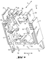
- a torsion spring 41 is mounted on the journal 11 in addition to the rocker switch 8.
- the longer of the two legs of the torsion spring 41 is supported on a spring stop 42. It has a slot-like outline shape and is integrally formed on the end shell 2, not shown in FIG. 2.
- the torsion spring 41 supports the switching movements of the rocker switch 8.
- Another torsion spring 43 supports the pivoting movements of the release lever 6.
- the torsion spring 43 is mounted on a fixing pin 44 which runs parallel to the axle pin 11 and is also formed on the housing wall 16.
- the longer of the two legs of the torsion spring 43 is supported on the lever arm of the release lever 6 running in the transverse direction 5.
- the shorter spring leg is supported on the release lever 6 in the area of the journal 10.
- a lever stop 45 with a rectangular outline shape is formed on the housing wall 16 between the bimetal 9 and the lever arm of the release lever 6 extending in the transverse direction 5.
- a cylindrical portion of the release lever 6 with the cylinder axis running in the row direction 3 bears against the lever stop 45.
- This partial area of the release lever 6 is penetrated by an elongated hole-like coupling bore 46 running in the row direction 3.
- the coupling bore 46 is penetrated by a coupling rod 47 to be described in FIG. 3 in the final assembly state.
- the latching lever 7 is penetrated by a coupling bore 48 in a cylindrical partial area.
- the coupling bore 48 is located in a free end, by means of which the link lever 7 acts on the release lever 6.
- the coupling bore 48 is circular. In the final assembly state of the circuit breaker, it is penetrated by a coupling rod 49 (FIG. 3).
- a rectangular housing slot 50 can be seen in FIG. 2 between the rocker switch 8 and the shift lever 6. Its long side runs in the transverse direction 5. It serves to enter an electrical contact path for a lighting assembly 51 (FIG. 4).
- the second contact path is formed by a columnar contact extension 52 running in the direction of attachment 4 (FIG. 4). It is an integral part of the contact connection 19.
- the lighting module 51 serves to visually display the switching position of the rocker switch 8.
- the insides of the free ends 25 are curved toward the rocker switch 8 in a concave manner and are arranged continuously along the mounting direction 4 at a parallel distance from the facing and also curved outer surface of the rocker switch 8.
- the cover collar 33 forms a continuation of the concave-like curvature of the inside of the free end 25 with its outer surface facing the curved side of the rocker switch 8 and inclined with respect to the mounting direction 4.
- rocker stop 53 Opposite the cover collar 33 in the mounting direction 4 is formed on the free end 25 facing the contact extension 52, a pin-like rocker stop 53 pointing in the direction of the axle pin 11.
- Another rocker stop 54 is formed on the free end 25 opposite in the transverse direction 5 at approximately the same height. It is also oriented towards the journal 11 and is approximately twice as long as the rocker stop 53. The two rocker stops 53, 54 serve to limit the switching movements of the rocker switch 8.
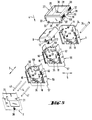
- the one-pole circuit breaker recognizable in FIG. 1 is expanded in FIG. 3 to a two-pole circuit breaker in that an intermediate housing shell 55 is inserted between the housing shell 1 and the end shell 2.
- the intermediate housing shell 55 is subdivided by an intermediate wall 56 along the row direction 3 into two partial regions, namely into a partial region acting as an end shell 2 and into a partial region acting as a housing shell 1.
- 3 shows the portion of the intermediate housing shell 55 which acts as the housing shell 1 and faces the end shell 2.
- the intermediate housing shell is configured in exactly the same way as the housing shell 1.
- an extension plate 57 is integrally formed on the outside of the housing base 18 of the housing intermediate wall 55. It lies in a plane spanned by the placement direction 4 and the transverse direction 5. Viewed in the row direction 3, it has an approximately rectangular outline shape. In the transverse direction 5, its extent corresponds to the distance between the two housing side walls 17 of the intermediate housing shell 55.
- the extension plate 57 acts as an extension of the intermediate wall 56 in the mounting direction 4.
- the extension plate 57 can serve, for example, to fix the intermediate housing shell 55 during the assembly of the circuit breaker housing, so that the individual shells 1, 2, 5 are technically easy to line up.
- the extension plate 57 can also serve for fixing and easy handling of the circuit breaker housing in the final assembly state.
- the area of the intermediate housing shell 55 opposite the housing base 18 along the mounting direction 4 and facing the rocker switch 8 is structurally changed compared to the corresponding area of the housing shell 1. While the housing side walls 17 of the intermediate housing shell 55 and the housing shell 1 are aligned with one another in the row direction 3 in the final assembly state, the intermediate wall 56 has a lower overall height compared to the housing wall 16 along the mounting direction 4. In the area of the housing side walls 17, the intermediate wall 56 terminates approximately with the rocker stops 53, 54. Viewed in the row direction 3, the intermediate wall 56, starting from the two rocker stops 53, 54, has an approximately conically tapered course in the direction of an axle pin 58 for pivoting the rocker switch 8.
- the cylindrical axle pin 58 with a longitudinal axis running in the row direction 3 is aligned with the axle pin 11 in the final assembly state
- the journal 58 protrudes on both sides of the intermediate wall 56 in the row direction 3.
- the approximately conical shape of the intermediate wall 56 with shoulder-shaped recesses takes into account the pivoting mobility of the rocker switch 8.
- the free ends 25 of the intermediate housing shell 55 extend the free ends 25 of the housing shell 1 in the row direction 3 and thereby enlarge the cross section of the housing shaft 24.
- the rocker switch 8 from FIG. 1 is widened in FIG Embodiment replaced.
- two ends 13 aligned with each other when viewed in the row direction 3 are also formed on the switching rocker 8 in FIG.
- the cover frame 27 from FIG. 1 is replaced by a cover frame 27 with frame walls 29 correspondingly elongated in the row direction 3.
- the spring arms 32 of the cover frame 27 from FIG. 3 are also widened in the row direction 3.
- the two spring arms 32 are separated from one another by a cover wall 59 formed on the frame wall 29 and running parallel to the frame walls 28.
- the tubular rivet 34 from FIG. 1 is also replaced in FIG. 3 by a corresponding tubular rivet 34 that is elongated in the row direction 3.
- the cam rod 14 from FIG. 1 for the mechanical coupling of the rocker switch 8 with the latching lever 7 is in FIG. 3 by a version extended in the row direction 3 exchanged.
- the cam rod 14 from FIG. 3 passes through the cam tracks 15 of the latching levers 7 of both poles, so that an approximately simultaneous pivoting movement of the two latching levers 7 occurs with an identical movement path.
- the cam rod 14 and the two coupling rods 47, 49 are arranged parallel to the row direction 3 in the final assembly state. They are approximately the same length and are designed as a cylindrical rod with approximately the same diameter.
- the latching levers 7 of the two switching mechanisms are also mechanically connected to one another by the coupling rod 49.
- the two release levers 6 are mechanically connected to one another by the coupling rod 47.
- the two trigger levers 6 are moved uniformly when only a single bimetal 9 is triggered. So that the cam rod 14 and the two coupling rods 47, 49 can be pivoted in the plane of movement of the release lever 6 and the latching lever 7 in accordance with their pivoting movements, the intermediate wall 56 is pierced by shaft recesses 60, 61, 62.
- the outline contour of the shaft recesses 60, 61, 62 is the somewhat enlarged image of the movement path of the cam rod 14 and the coupling rods 47, 49 taking place in the direction of the row 3.
- the shaft recess 60 is assigned to the coupling rod 49 and has an elongated cross-section.
- the long sides of the slot-like shaft recess 60 run at an acute angle to the mounting direction 4 and are inclined in the direction of the rocker stop 53.
- the shaft recess 61 is approximately at the same height as the shaft recess 60. It has a rectangular cross section with rounded corners in the shape of a quarter circle. The long sides of this rectangle run in the transverse direction 5.
- the shaft recess 61 is assigned to the cam rod 14 and is arranged between the shaft recess 60 and the guide pin 40.
- the shaft recess 62 has a slot-like outline shape and is assigned to the coupling rod 47.
- the longitudinal sides of the shaft recess 62 run approximately parallel to the mounting direction 4. It is arranged between the guide pin 40 and the lever stop 45.
- the lighting assembly 51 is clearly visible in FIG. It essentially consists of a printed circuit board 63, a glow lamp 64 and a resistor 65. Instead of a glow lamp 64, an incandescent lamp or an LED can also be used.
- the lighting assembly 51 is in the case of a multi-pole Circuit breaker plugged onto the contact extensions 52 of two adjacent intermediate housing shells 55 and soldered. The current paths on the circuit board 63 are guided so that the desired electrical connections are realized. If it is a single-pole circuit breaker, the circuit board 63 is mounted with a connection on the contact extension 52 of the contact connection 19. The second electrical connection is brought to the circuit board 63 via the housing slot 50.
- a cover wall 59 is also assigned to each spring arm 32. This also improves the mechanical stability of the frame wall 29.
- the procedure for installing the circuit breaker is as follows. First, a number of intermediate housing shells 55 corresponding to the desired number of poles of the circuit breaker is lined up in row direction 3. The following applies: n-1 intermediate shells 55 are required for n poles.
- the switching mechanism is already mounted on each intermediate housing shell 55. When the intermediate housing shells 55 are lined up, the rocker switch 8 must also be pivoted by means of the journal 58. If the required number of intermediate housing shells 55 has been joined together, the housing shell 1 is attached to the intermediate housing shell 55 that is also located with the switching mechanism already mounted. It must be ensured that the axle pin 11 engages in the axle bore 12 of the rocker switch 8.
- the cam rod 14 is then inserted through all the cam tracks 15, through the holes in the ends 13 and through the shaft recesses 61.
- the coupling rod 47 is inserted in the same way in the row direction 3 through all coupling bores 46 and all shaft recesses 62. Analogously to this, the coupling rod 49 passes through all coupling bores 48 and all shaft cutouts 60 in the final assembly state.
- the end shell 2 is then attached to the her nearest housing intermediate shell 55 attached.
- the circuit breaker housing is closed on all sides in row direction 3 and transverse direction 5.
- the cover frame 27 is then pushed onto the housing shaft 24 in the mounting direction 4.
- the cover frame 27 is locked in place with the housing shell 1 and with the end shell 2 and in this way holds all the shells 1, 2, 5 in the region of the housing shaft 24 in a mechanically stable manner.
- the tubular rivet 34 is pushed through the aligned cylinder bores 35 and the rivet bore 36 in the row direction 3.
- the shells 1, 2, 5 are also connected to one another in a mechanically stable manner in the region of the housing base 18.
Landscapes
- Breakers (AREA)
- Driving Mechanisms And Operating Circuits Of Arc-Extinguishing High-Tension Switches (AREA)
- Air Bags (AREA)
- Jib Cranes (AREA)
- Control Of Combustion (AREA)
- Switch Cases, Indication, And Locking (AREA)
Priority Applications (1)
| Application Number | Priority Date | Filing Date | Title |
|---|---|---|---|
| DE9422029U DE9422029U1 (de) | 1993-03-17 | 1994-01-25 | Mehrpoliger Schutzschalter |
Applications Claiming Priority (2)
| Application Number | Priority Date | Filing Date | Title |
|---|---|---|---|
| DE9303918 | 1993-03-17 | ||
| DE9303918U | 1993-03-17 |
Publications (2)
| Publication Number | Publication Date |
|---|---|
| EP0616347A1 true EP0616347A1 (fr) | 1994-09-21 |
| EP0616347B1 EP0616347B1 (fr) | 1998-03-11 |
Family
ID=6890753
Family Applications (1)
| Application Number | Title | Priority Date | Filing Date |
|---|---|---|---|
| EP94101023A Expired - Lifetime EP0616347B1 (fr) | 1993-03-17 | 1994-01-25 | Disjoncteur multipolaire |
Country Status (9)
| Country | Link |
|---|---|
| US (1) | US5451729A (fr) |
| EP (1) | EP0616347B1 (fr) |
| JP (1) | JP2760944B2 (fr) |
| KR (1) | KR0151219B1 (fr) |
| AT (1) | ATE164027T1 (fr) |
| DE (2) | DE59405409D1 (fr) |
| DK (1) | DK0616347T3 (fr) |
| ES (1) | ES2115086T3 (fr) |
| TW (1) | TW289832B (fr) |
Cited By (4)
| Publication number | Priority date | Publication date | Assignee | Title |
|---|---|---|---|---|
| EP1037238A3 (fr) * | 1999-03-11 | 2001-10-31 | Ellenberger & Poensgen GmbH | Disjoncteur de surintensité |
| WO2010145757A1 (fr) * | 2009-06-19 | 2010-12-23 | Ellenberger & Poensgen Gmbh | Procédé de commande du déclenchement d'un disjoncteur de protection électronique |
| DE102009025513A1 (de) | 2009-06-19 | 2010-12-30 | Ellenberger & Poensgen Gmbh | Elektronischer Schutzschalter |
| CN102915857A (zh) * | 2011-08-02 | 2013-02-06 | 法纳通电器(上海)有限公司 | 墙壁开关 |
Families Citing this family (134)
| Publication number | Priority date | Publication date | Assignee | Title |
|---|---|---|---|---|
| IT1292453B1 (it) | 1997-07-02 | 1999-02-08 | Aeg Niederspannungstech Gmbh | Gruppo rotante di contatti per interrutttori di alta portata |
| DE19819242B4 (de) | 1998-04-29 | 2005-11-10 | Ge Power Controls Polska Sp.Z.O.O. | Thermomagnetischer Leistungsschalter |
| US6114641A (en) | 1998-05-29 | 2000-09-05 | General Electric Company | Rotary contact assembly for high ampere-rated circuit breakers |
| DE19835068A1 (de) * | 1998-08-04 | 2000-02-10 | Zeiss Carl Jena Gmbh | Mikroskop, insbesondere Laser-Scanning-Mikroskop |
| US6087913A (en) | 1998-11-20 | 2000-07-11 | General Electric Company | Circuit breaker mechanism for a rotary contact system |
| US6037555A (en) | 1999-01-05 | 2000-03-14 | General Electric Company | Rotary contact circuit breaker venting arrangement including current transformer |
| US6166344A (en) | 1999-03-23 | 2000-12-26 | General Electric Company | Circuit breaker handle block |
| US6262872B1 (en) | 1999-06-03 | 2001-07-17 | General Electric Company | Electronic trip unit with user-adjustable sensitivity to current spikes |
| US6094126A (en) * | 1999-06-08 | 2000-07-25 | Sorenson; Richard W. | Thermal circuit breaker switch |
| TW453504U (en) * | 1999-06-24 | 2001-09-01 | You Tsung Mou | Button switch having overload protection function |
| TW427544U (en) | 1999-06-24 | 2001-03-21 | You Tsung Mou | Pressing-key switch with overload protection function |
| TW515567U (en) | 1999-06-24 | 2002-12-21 | Tsung-Mou You | Push button type switch having overload protection and automatic reload function |
| US6268991B1 (en) | 1999-06-25 | 2001-07-31 | General Electric Company | Method and arrangement for customizing electronic circuit interrupters |
| US6218917B1 (en) | 1999-07-02 | 2001-04-17 | General Electric Company | Method and arrangement for calibration of circuit breaker thermal trip unit |
| US6188036B1 (en) | 1999-08-03 | 2001-02-13 | General Electric Company | Bottom vented circuit breaker capable of top down assembly onto equipment |
| US6710988B1 (en) | 1999-08-17 | 2004-03-23 | General Electric Company | Small-sized industrial rated electric motor starter switch unit |
| US6252365B1 (en) | 1999-08-17 | 2001-06-26 | General Electric Company | Breaker/starter with auto-configurable trip unit |
| US6396369B1 (en) | 1999-08-27 | 2002-05-28 | General Electric Company | Rotary contact assembly for high ampere-rated circuit breakers |
| US6175288B1 (en) | 1999-08-27 | 2001-01-16 | General Electric Company | Supplemental trip unit for rotary circuit interrupters |
| US6232570B1 (en) | 1999-09-16 | 2001-05-15 | General Electric Company | Arcing contact arrangement |
| US6249209B1 (en) * | 1999-09-17 | 2001-06-19 | Tsung-Mou Yu | Switch structure having a current overloading protection mechanism |
| US6326869B1 (en) | 1999-09-23 | 2001-12-04 | General Electric Company | Clapper armature system for a circuit breaker |
| US6239395B1 (en) | 1999-10-14 | 2001-05-29 | General Electric Company | Auxiliary position switch assembly for a circuit breaker |
| US6229413B1 (en) | 1999-10-19 | 2001-05-08 | General Electric Company | Support of stationary conductors for a circuit breaker |
| US6252490B1 (en) * | 1999-10-21 | 2001-06-26 | Wen-Jang Lin | Safety plug and switch device |
| US6317018B1 (en) | 1999-10-26 | 2001-11-13 | General Electric Company | Circuit breaker mechanism |
| TW456574U (en) | 1999-10-29 | 2001-09-21 | You Tsung Mou | Overload protection push button switch with indirectly driven auto-reset activated mechanism |
| US6232856B1 (en) | 1999-11-02 | 2001-05-15 | General Electric Company | Magnetic shunt assembly |
| US6377144B1 (en) | 1999-11-03 | 2002-04-23 | General Electric Company | Molded case circuit breaker base and mid-cover assembly |
| ES2249875T3 (es) | 1999-11-03 | 2006-04-01 | AEG NIEDERSPANNUNGSTECHNIK GMBH & CO. KG | Disposicion de brazo de contacto rotatorio para disyuntor. |
| US6252489B1 (en) * | 1999-11-10 | 2001-06-26 | Tsung-Mou Yu | Switch structure |
| US6275133B1 (en) * | 1999-12-03 | 2001-08-14 | Tsung-Mou Yu | Switch structure |
| US6300586B1 (en) | 1999-12-09 | 2001-10-09 | General Electric Company | Arc runner retaining feature |
| US6310307B1 (en) | 1999-12-17 | 2001-10-30 | General Electric Company | Circuit breaker rotary contact arm arrangement |
| US6172584B1 (en) | 1999-12-20 | 2001-01-09 | General Electric Company | Circuit breaker accessory reset system |
| US6184761B1 (en) | 1999-12-20 | 2001-02-06 | General Electric Company | Circuit breaker rotary contact arrangement |
| US6215379B1 (en) | 1999-12-23 | 2001-04-10 | General Electric Company | Shunt for indirectly heated bimetallic strip |
| US6281461B1 (en) | 1999-12-27 | 2001-08-28 | General Electric Company | Circuit breaker rotor assembly having arc prevention structure |
| US6346869B1 (en) | 1999-12-28 | 2002-02-12 | General Electric Company | Rating plug for circuit breakers |
| TW462531U (en) | 1999-12-30 | 2001-11-01 | You Tsung Mou | Over-load protection type button switch with drawing type auto-reset driven mechanism |
| TW475775U (en) | 1999-12-30 | 2002-02-01 | Tsung-Mou You | Overload protection type push button switch having an intermittent retractable activated mechanism |
| US6307459B1 (en) * | 2000-01-05 | 2001-10-23 | Tsung-Mou Yu | Power switch device |
| US6384354B1 (en) * | 2000-01-08 | 2002-05-07 | Michael Shotey | Cover for electrical switch |
| US6211758B1 (en) | 2000-01-11 | 2001-04-03 | General Electric Company | Circuit breaker accessory gap control mechanism |
| US6353380B1 (en) * | 2000-01-27 | 2002-03-05 | Tsung-Mou Yu | Power switch device |
| US6307460B1 (en) * | 2000-02-01 | 2001-10-23 | Tsung-Mou Yu | Power switch device |
| US6239677B1 (en) | 2000-02-10 | 2001-05-29 | General Electric Company | Circuit breaker thermal magnetic trip unit |
| US6429759B1 (en) | 2000-02-14 | 2002-08-06 | General Electric Company | Split and angled contacts |
| US6313425B1 (en) | 2000-02-24 | 2001-11-06 | General Electric Company | Cassette assembly with rejection features |
| US6281458B1 (en) | 2000-02-24 | 2001-08-28 | General Electric Company | Circuit breaker auxiliary magnetic trip unit with pressure sensitive release |
| US6404314B1 (en) | 2000-02-29 | 2002-06-11 | General Electric Company | Adjustable trip solenoid |
| US6204743B1 (en) | 2000-02-29 | 2001-03-20 | General Electric Company | Dual connector strap for a rotary contact circuit breaker |
| US6379196B1 (en) | 2000-03-01 | 2002-04-30 | General Electric Company | Terminal connector for a circuit breaker |
| US6340925B1 (en) | 2000-03-01 | 2002-01-22 | General Electric Company | Circuit breaker mechanism tripping cam |
| US6448521B1 (en) | 2000-03-01 | 2002-09-10 | General Electric Company | Blocking apparatus for circuit breaker contact structure |
| US6346868B1 (en) | 2000-03-01 | 2002-02-12 | General Electric Company | Circuit interrupter operating mechanism |
| US6211757B1 (en) | 2000-03-06 | 2001-04-03 | General Electric Company | Fast acting high force trip actuator |
| US6459349B1 (en) | 2000-03-06 | 2002-10-01 | General Electric Company | Circuit breaker comprising a current transformer with a partial air gap |
| US6366438B1 (en) | 2000-03-06 | 2002-04-02 | General Electric Company | Circuit interrupter rotary contact arm |
| US6496347B1 (en) | 2000-03-08 | 2002-12-17 | General Electric Company | System and method for optimization of a circuit breaker mechanism |
| US6429659B1 (en) | 2000-03-09 | 2002-08-06 | General Electric Company | Connection tester for an electronic trip unit |
| US6232859B1 (en) | 2000-03-15 | 2001-05-15 | General Electric Company | Auxiliary switch mounting configuration for use in a molded case circuit breaker |
| US6366188B1 (en) | 2000-03-15 | 2002-04-02 | General Electric Company | Accessory and recess identification system for circuit breakers |
| US6218919B1 (en) | 2000-03-15 | 2001-04-17 | General Electric Company | Circuit breaker latch mechanism with decreased trip time |
| US6459059B1 (en) | 2000-03-16 | 2002-10-01 | General Electric Company | Return spring for a circuit interrupter operating mechanism |
| US6421217B1 (en) | 2000-03-16 | 2002-07-16 | General Electric Company | Circuit breaker accessory reset system |
| US6559743B2 (en) | 2000-03-17 | 2003-05-06 | General Electric Company | Stored energy system for breaker operating mechanism |
| US6373010B1 (en) | 2000-03-17 | 2002-04-16 | General Electric Company | Adjustable energy storage mechanism for a circuit breaker motor operator |
| US6476698B1 (en) | 2000-03-17 | 2002-11-05 | General Electric Company | Convertible locking arrangement on breakers |
| FR2806548B1 (fr) | 2000-03-17 | 2002-08-23 | Ge Power Controls France | Mecanisme extractible pour disjoncteurs |
| US6388213B1 (en) | 2000-03-17 | 2002-05-14 | General Electric Company | Locking device for molded case circuit breakers |
| US6472620B2 (en) | 2000-03-17 | 2002-10-29 | Ge Power Controls France Sas | Locking arrangement for circuit breaker draw-out mechanism |
| US6479774B1 (en) | 2000-03-17 | 2002-11-12 | General Electric Company | High energy closing mechanism for circuit breakers |
| US6586693B2 (en) | 2000-03-17 | 2003-07-01 | General Electric Company | Self compensating latch arrangement |
| DE10013103C1 (de) * | 2000-03-17 | 2001-11-29 | Aeg Niederspannungstech Gmbh | Gehäuse |
| US6639168B1 (en) | 2000-03-17 | 2003-10-28 | General Electric Company | Energy absorbing contact arm stop |
| US6392171B1 (en) * | 2000-03-27 | 2002-05-21 | Chiung-Ying Linhuang | Integral multi-switch |
| US6747535B2 (en) | 2000-03-27 | 2004-06-08 | General Electric Company | Precision location system between actuator accessory and mechanism |
| US6995640B2 (en) | 2000-05-16 | 2006-02-07 | General Electric Company | Pressure sensitive trip mechanism for circuit breakers |
| US6373357B1 (en) | 2000-05-16 | 2002-04-16 | General Electric Company | Pressure sensitive trip mechanism for a rotary breaker |
| TW478641U (en) | 2000-06-13 | 2002-03-01 | Tsung-Mou You | Cyclic type push button switch having overload protection |
| US6469610B1 (en) * | 2000-07-28 | 2002-10-22 | Tsung-Mou Yu | Switch assembly |
| US6323450B1 (en) * | 2000-07-28 | 2001-11-27 | Tsung-Mou Yu | Switch assembly |
| US6326572B1 (en) | 2000-09-02 | 2001-12-04 | Tsung-Mou Yu | Push-button switch assembly |
| US6400245B1 (en) | 2000-10-13 | 2002-06-04 | General Electric Company | Draw out interlock for circuit breakers |
| US6429760B1 (en) | 2000-10-19 | 2002-08-06 | General Electric Company | Cross bar for a conductor in a rotary breaker |
| US6531941B1 (en) | 2000-10-19 | 2003-03-11 | General Electric Company | Clip for a conductor in a rotary breaker |
| US6806800B1 (en) | 2000-10-19 | 2004-10-19 | General Electric Company | Assembly for mounting a motor operator on a circuit breaker |
| US6444931B1 (en) * | 2000-10-31 | 2002-09-03 | Alcatel Usa Sourcing, L.P. | Modular circuit breaker housing assembly |
| US6362711B1 (en) | 2000-11-10 | 2002-03-26 | General Electric Company | Circuit breaker cover with screw locating feature |
| US6380829B1 (en) | 2000-11-21 | 2002-04-30 | General Electric Company | Motor operator interlock and method for circuit breakers |
| US6448522B1 (en) | 2001-01-30 | 2002-09-10 | General Electric Company | Compact high speed motor operator for a circuit breaker |
| US6483416B2 (en) * | 2001-02-22 | 2002-11-19 | Tsung-Mou Yu | Overload protection device of a press type switch |
| US6476337B2 (en) | 2001-02-26 | 2002-11-05 | General Electric Company | Auxiliary switch actuation arrangement |
| US6882258B2 (en) | 2001-02-27 | 2005-04-19 | General Electric Company | Mechanical bell alarm assembly for a circuit breaker |
| US6452125B1 (en) | 2001-03-17 | 2002-09-17 | Tsung-Mou Yu | Switch with an override interruption structure |
| US6525639B1 (en) * | 2001-08-15 | 2003-02-25 | Tsang-I Cheng | Power source electrical switch |
| US6678135B2 (en) | 2001-09-12 | 2004-01-13 | General Electric Company | Module plug for an electronic trip unit |
| US6469882B1 (en) | 2001-10-31 | 2002-10-22 | General Electric Company | Current transformer initial condition correction |
| US6804101B2 (en) | 2001-11-06 | 2004-10-12 | General Electric Company | Digital rating plug for electronic trip unit in circuit breakers |
| US6713693B1 (en) * | 2003-01-30 | 2004-03-30 | Carling Technologies, Inc. | Electric switch having both toggle and rocker functions |
| US6713704B1 (en) | 2003-02-03 | 2004-03-30 | Tsung-Mou Yu | Pushbutton assembly |
| US6818848B2 (en) * | 2003-02-03 | 2004-11-16 | Tsung-Mou Yu | Pushbutton assembly with positioning rod and disk |
| US6800826B1 (en) | 2003-05-24 | 2004-10-05 | Tsung-Mou Yu | Activation mechanism for switch devices |
| US6788186B1 (en) * | 2003-05-31 | 2004-09-07 | Tsung-Mou Yu | Activation mechanism for switch devices |
| US6753491B1 (en) * | 2003-09-10 | 2004-06-22 | Albert Huang | Circuit breaker for a dual-circuit |
| US7026564B1 (en) * | 2004-01-27 | 2006-04-11 | Pass & Seymour/Legrand | Paddle switch assembly |
| US6894241B1 (en) | 2004-02-26 | 2005-05-17 | Tsung-Mou Yu | Resilient switching device |
| US6884955B1 (en) | 2004-04-20 | 2005-04-26 | Tsung-Mou Yu | Circuit breaker on a pushbutton switch having a linkage movably connected to the pushbutton so as to allow free movement of a heat sensitive plate |
| US6933455B1 (en) * | 2004-04-28 | 2005-08-23 | Tsung-Mou Yu | Circuit breaker on a pushbutton switch |
| US20050252757A1 (en) * | 2004-05-14 | 2005-11-17 | May Galen J | Residential circuit breaker having a tripped switch indicator means |
| US6940389B1 (en) | 2004-05-14 | 2005-09-06 | Tsung-Mou Yu | Mechanism for ensuring bimetallic plate to be deformed without barrier |
| US7148784B2 (en) * | 2004-05-26 | 2006-12-12 | Tsung-Mou Yu | Safety switch device |
| US7005957B2 (en) | 2004-05-29 | 2006-02-28 | Tsung-Mou Yu | Mechanism for trip-free of the bimetallic plate of a safety switch device |
| US7202769B2 (en) * | 2004-06-19 | 2007-04-10 | Tsung-Mou Yu | Protection mechanism for switch |
| US6864453B1 (en) | 2004-07-08 | 2005-03-08 | Tsung-Mou Yu | Protection mechanism for switch |
| US7034650B2 (en) | 2004-07-10 | 2006-04-25 | Tsung-Mou Yu | Protection mechanism for switches |
| US7030726B2 (en) * | 2004-07-10 | 2006-04-18 | Tsung-Mou Yu | Protection mechanism for switches |
| WO2006097164A1 (fr) | 2005-03-12 | 2006-09-21 | Ellenberger & Poensgen Gmbh | Disjoncteur de protection pour la protection d'un circuit électrique |
| US7292129B2 (en) * | 2005-07-02 | 2007-11-06 | Tsung-Mou Yu | Protection device for switches |
| US7656268B2 (en) * | 2005-07-02 | 2010-02-02 | Tsung-Mou Yu | Safety switch |
| DE102005038149A1 (de) | 2005-08-12 | 2007-02-22 | Abb Patent Gmbh | Leitungsschutzschalter |
| JP4852337B2 (ja) * | 2006-04-25 | 2012-01-11 | 河村電器産業株式会社 | 配線用遮断器 |
| US7583174B2 (en) * | 2007-11-14 | 2009-09-01 | Tsung Mou Yu | Safety switch |
| US7583175B2 (en) * | 2007-11-16 | 2009-09-01 | Tsung Mou Yu | Safety switch |
| US7755465B2 (en) * | 2008-04-23 | 2010-07-13 | Sun-Lite Sockets Industry Inc. | Temperature control switch |
| CN201663068U (zh) * | 2010-04-22 | 2010-12-01 | 南京德朔实业有限公司 | 用于动力工具上的开关改良结构 |
| EP2597665A1 (fr) * | 2011-11-24 | 2013-05-29 | Eaton Industries GmbH | Commutateur pour courant continu doté d'au moins une chambre de commutation |
| CA2939551C (fr) | 2014-02-13 | 2021-06-08 | Ellenberger & Poensgen Gmbh | Disjoncteur thermique de protection contre les surintensites |
| DE202014010312U1 (de) | 2014-02-13 | 2015-06-15 | Ellenberger & Poensgen Gmbh | Thermischer Überstromschutzschalter |
| US11189447B2 (en) * | 2014-03-28 | 2021-11-30 | Yaowu Hua | Time switch of controllable time adjustment |
| US9373465B1 (en) | 2015-04-10 | 2016-06-21 | Tsung-Mou Yu | Switch with overload release structure |
| CN105632847B (zh) * | 2016-03-30 | 2017-10-24 | 陈德伦 | 一种具有自动脱扣功能的开关机构 |
| USD938369S1 (en) * | 2019-10-21 | 2021-12-14 | Ellenberger & Poensgen Gmbh | Combined electrical switch with mounting plate |
Citations (6)
| Publication number | Priority date | Publication date | Assignee | Title |
|---|---|---|---|---|
| US2913542A (en) * | 1957-10-23 | 1959-11-17 | Ite Circuit Breaker Ltd | Two pole circuit breaker |
| DE1964782U (de) * | 1967-03-07 | 1967-07-27 | Siemens Ag | Mehrpoliger leitungsschutzschalter. |
| FR2390824A1 (fr) * | 1977-05-11 | 1978-12-08 | Ellenberger & Poensgen | Disjoncteur a maximum de courant a bascule de fermeture-coupure |
| DE8520327U1 (de) * | 1985-07-13 | 1985-10-03 | Sursum Elektrizitätsgesellschaft Leyhausen GmbH & Co, 8500 Nürnberg | Installationsgerät mit Rohrnieten |
| EP0208613A1 (fr) * | 1985-07-05 | 1987-01-14 | Telemecanique | Interrupteur de protection à pôles accouplables |
| DE4034392A1 (de) * | 1989-10-31 | 1991-05-02 | Abb Elettrocondutture Spa | Miniaturisierter schaltautomat mit modularem aufbau fuer elektrische haushaltsanlagen, industrieanlagen und dergleichen |
Family Cites Families (29)
| Publication number | Priority date | Publication date | Assignee | Title |
|---|---|---|---|---|
| DE326752C (de) * | 1920-02-03 | 1920-10-02 | Grimme Natalis & Co Komm Ges A | Vorrichtung zum OEffnen von Konservendosen |
| DE753881C (de) * | 1942-04-11 | 1952-08-28 | Aeg | Gemeinsame Einstellvorrichtung fuer den Ausloesestrom der auf eine gemeinsame Ausloesewelle wirkenden Waermeausloeser von Motor-schutzschaltern |
| DE1101575B (de) * | 1959-01-16 | 1961-03-09 | Hochkoepper & Co P | Schalter mit Anzeigelampe |
| NL134085C (fr) * | 1963-06-05 | |||
| US3256407A (en) * | 1963-10-28 | 1966-06-14 | Gen Electric | Circuit breaker and accessory device combination |
| DE1463116B2 (de) * | 1963-11-27 | 1970-07-16 | Ellenberger & Poensgen Gmbh, 8503 Altdorf | Mit einem Klemmenbrett verbundene druckknopfbetätigte überstromschalter |
| US3341791A (en) * | 1964-06-16 | 1967-09-12 | Square D Co | Electric circuit breaker with improved operating mechanism |
| JPS494706B1 (fr) * | 1964-12-30 | 1974-02-02 | ||
| US3383486A (en) * | 1967-04-17 | 1968-05-14 | Gen Electric | Electric circuit breaker with combined plug-in terminal and contact support |
| DE1763252C3 (de) * | 1968-04-25 | 1978-10-19 | Baer Elektrowerke Kg, 5885 Schalksmuehle | Einbauschalter, insbesondere Kippschalter |
| DK152157C (da) * | 1976-12-10 | 1988-06-20 | Knudsen Nordisk Elect | Gruppeafbryder |
| GB2011722B (en) * | 1977-10-18 | 1982-05-06 | Parr D | Electric switches |
| DE2928277C2 (de) * | 1979-07-13 | 1983-12-01 | Ellenberger & Poensgen Gmbh, 8503 Altdorf | Kombinierbarer zweipoliger Überstromschutzschalter |
| CH647094A5 (en) * | 1979-11-09 | 1984-12-28 | Weber Ag Fab Elektro | Two-pole protective circuit breaker with thermal tripping |
| DE8111050U1 (de) * | 1981-04-11 | 1981-10-01 | Bär Elektrowerke KG, 5885 Schalksmühle | "Elektrischer Schalter" |
| US4363016A (en) * | 1981-06-03 | 1982-12-07 | Amf Incorporated | Circuit breaker |
| JPS5931817A (ja) * | 1982-08-13 | 1984-02-21 | Nippon Steel Corp | 熱量配分装置 |
| JPS59197288A (ja) * | 1983-04-25 | 1984-11-08 | 株式会社東芝 | 洗濯機 |
| DD221878A1 (de) * | 1984-03-12 | 1985-05-02 | Elektroinstallation Annaberg V | Mehrpoliger leitungsschutzschalter |
| DD224150A1 (de) * | 1984-05-17 | 1985-06-26 | Oppach Schaltelektronik | Motorschutzrelais |
| DE3701275A1 (de) * | 1987-01-17 | 1988-07-28 | Vorwerk Co Interholding | Ueberstromschutz-schnappschalter fuer haushaltsgeraete |
| IT212320Z2 (it) * | 1987-10-16 | 1989-07-04 | Valvar Spa | Interruttore elettrico a scatto rapido per il comando di dispositivo alzacristalli di un autoveicolo |
| DE3802765A1 (de) * | 1988-01-30 | 1989-08-10 | Insta Elektro Gmbh & Co Kg | Schaltvorrichtung fuer ein elektrisches installationsgeraet, insbesondere 2-polig abschaltbare steckdose |
| DE3918567B4 (de) * | 1988-02-08 | 2004-07-08 | Saia-Burgess Halver Gmbh & Co.Kg | Wippenschalter |
| US4931762A (en) * | 1989-04-13 | 1990-06-05 | Heinemann Electric Company | Circuit breaker construction |
| JPH0722029Y2 (ja) * | 1989-10-09 | 1995-05-17 | ホシデン株式会社 | 自照式電源スイッチ付回路遮断器 |
| DE3935280A1 (de) * | 1989-10-24 | 1991-05-16 | Guenter Trautmann | Sicherheits - stromunterbrecher in wasserdichter gummi-manschette zum an - oder einbau in elektrische geraete |
| US4937548A (en) * | 1989-10-25 | 1990-06-26 | Mechanical Products, Inc. | Circuit breaker |
| DE9104076U1 (de) * | 1990-04-06 | 1991-07-18 | Ellenberger & Poensgen GmbH, 90518 Altdorf | Druckknopfbetätigter Schutzschalter |
-
1994
- 1994-01-25 AT AT94101023T patent/ATE164027T1/de not_active IP Right Cessation
- 1994-01-25 DK DK94101023T patent/DK0616347T3/da active
- 1994-01-25 EP EP94101023A patent/EP0616347B1/fr not_active Expired - Lifetime
- 1994-01-25 DE DE59405409T patent/DE59405409D1/de not_active Expired - Lifetime
- 1994-01-25 ES ES94101023T patent/ES2115086T3/es not_active Expired - Lifetime
- 1994-01-25 DE DE9422029U patent/DE9422029U1/de not_active Expired - Lifetime
- 1994-01-28 TW TW083100717A patent/TW289832B/zh not_active IP Right Cessation
- 1994-03-14 KR KR1019940004979A patent/KR0151219B1/ko not_active Expired - Lifetime
- 1994-03-17 US US08/214,151 patent/US5451729A/en not_active Expired - Lifetime
- 1994-03-17 JP JP6047114A patent/JP2760944B2/ja not_active Expired - Lifetime
Patent Citations (6)
| Publication number | Priority date | Publication date | Assignee | Title |
|---|---|---|---|---|
| US2913542A (en) * | 1957-10-23 | 1959-11-17 | Ite Circuit Breaker Ltd | Two pole circuit breaker |
| DE1964782U (de) * | 1967-03-07 | 1967-07-27 | Siemens Ag | Mehrpoliger leitungsschutzschalter. |
| FR2390824A1 (fr) * | 1977-05-11 | 1978-12-08 | Ellenberger & Poensgen | Disjoncteur a maximum de courant a bascule de fermeture-coupure |
| EP0208613A1 (fr) * | 1985-07-05 | 1987-01-14 | Telemecanique | Interrupteur de protection à pôles accouplables |
| DE8520327U1 (de) * | 1985-07-13 | 1985-10-03 | Sursum Elektrizitätsgesellschaft Leyhausen GmbH & Co, 8500 Nürnberg | Installationsgerät mit Rohrnieten |
| DE4034392A1 (de) * | 1989-10-31 | 1991-05-02 | Abb Elettrocondutture Spa | Miniaturisierter schaltautomat mit modularem aufbau fuer elektrische haushaltsanlagen, industrieanlagen und dergleichen |
Cited By (7)
| Publication number | Priority date | Publication date | Assignee | Title |
|---|---|---|---|---|
| EP1037238A3 (fr) * | 1999-03-11 | 2001-10-31 | Ellenberger & Poensgen GmbH | Disjoncteur de surintensité |
| WO2010145757A1 (fr) * | 2009-06-19 | 2010-12-23 | Ellenberger & Poensgen Gmbh | Procédé de commande du déclenchement d'un disjoncteur de protection électronique |
| DE102009025513A1 (de) | 2009-06-19 | 2010-12-30 | Ellenberger & Poensgen Gmbh | Elektronischer Schutzschalter |
| CN102804319A (zh) * | 2009-06-19 | 2012-11-28 | 埃伦贝格尔及珀恩斯根有限公司 | 电子保护开关 |
| CN102804319B (zh) * | 2009-06-19 | 2015-09-30 | 埃伦贝格尔及珀恩斯根有限公司 | 电子保护开关 |
| CN102915857A (zh) * | 2011-08-02 | 2013-02-06 | 法纳通电器(上海)有限公司 | 墙壁开关 |
| CN102915857B (zh) * | 2011-08-02 | 2015-04-01 | 法纳通电器(上海)有限公司 | 墙壁开关 |
Also Published As
| Publication number | Publication date |
|---|---|
| DE9422029U1 (de) | 1997-09-18 |
| KR940022612A (ko) | 1994-10-21 |
| JP2760944B2 (ja) | 1998-06-04 |
| US5451729A (en) | 1995-09-19 |
| EP0616347B1 (fr) | 1998-03-11 |
| DE59405409D1 (de) | 1998-04-16 |
| ATE164027T1 (de) | 1998-03-15 |
| ES2115086T3 (es) | 1998-06-16 |
| KR0151219B1 (ko) | 1998-10-15 |
| TW289832B (fr) | 1996-11-01 |
| JPH06325679A (ja) | 1994-11-25 |
| DK0616347T3 (da) | 1998-10-07 |
Similar Documents
| Publication | Publication Date | Title |
|---|---|---|
| EP0616347B1 (fr) | Disjoncteur multipolaire | |
| EP3454422A1 (fr) | Borne de connexion conductrice | |
| EP1995754A1 (fr) | Commutateur d'installation électrique | |
| EP0563775B1 (fr) | Disjoncteur de protection commandé par bimétal | |
| EP1405325A1 (fr) | Appareil de connexion a verrouillage de connexion | |
| DE69513746T2 (de) | Schutzschalter | |
| EP0450366B1 (fr) | Disjoncteur commandé par bouton-poussoir | |
| EP1218900B1 (fr) | Dispositif permettant de poser l'arbre de commande d'un disjoncteur basse tension et disjoncteur basse tension multipolaire dote de ce dispositif | |
| DE3851093T2 (de) | Mehrpoliger Schalter. | |
| EP0188482B1 (fr) | Verrou de commutation | |
| EP1405324B1 (fr) | Dispositif de commutation muni d'un verrouillage de connexion | |
| DE3602123A1 (de) | Sicherungsautomat mit einem elektromagnet zur fernsteuerung eines wegrueckbaren unterbrecherkontakts und einem organ zur uebertragung der bewegung des ankers des elektromagnets auf einen bezueglich der bewegung des ankers versetzten punkt dieses kontakts | |
| EP0802552A2 (fr) | Interrupteur électrique à déclenchement par manque de tension | |
| DD221878A1 (de) | Mehrpoliger leitungsschutzschalter | |
| EP0634051B1 (fr) | Disjoncteur multipolaire a basse tension avec arbre de commande | |
| EP1065683B1 (fr) | Disjoncteur aves des bornes pour plusieurs intensités nominales | |
| DE2717444C2 (de) | Mehrpoliges thermisches Überstromrelais | |
| DE3734396A1 (de) | Elektrisches schaltgeraet | |
| EP0849748A2 (fr) | Interrupteur électrique d'installation | |
| DE3501480C2 (de) | Niederspannungs-Leistungsschalter mit in einer gesonderten Kammer angeordnetem Schaltschloß | |
| EP0043406B1 (fr) | Elément interrupteur de protection pour être ajouté à un appareil interrupteur construit comme interrupteur rotatif | |
| DE3425996C2 (fr) | ||
| EP0529278B1 (fr) | Appareillage électrique | |
| EP1110229B1 (fr) | Appareil d'installation a support axial indeformable | |
| EP2649626B1 (fr) | Arrangement de commutation |
Legal Events
| Date | Code | Title | Description |
|---|---|---|---|
| PUAI | Public reference made under article 153(3) epc to a published international application that has entered the european phase |
Free format text: ORIGINAL CODE: 0009012 |
|
| AK | Designated contracting states |
Kind code of ref document: A1 Designated state(s): AT BE CH DE DK ES FR GB GR IE IT LI LU MC NL PT SE |
|
| 17P | Request for examination filed |
Effective date: 19940907 |
|
| 17Q | First examination report despatched |
Effective date: 19960212 |
|
| GRAG | Despatch of communication of intention to grant |
Free format text: ORIGINAL CODE: EPIDOS AGRA |
|
| GRAG | Despatch of communication of intention to grant |
Free format text: ORIGINAL CODE: EPIDOS AGRA |
|
| GRAH | Despatch of communication of intention to grant a patent |
Free format text: ORIGINAL CODE: EPIDOS IGRA |
|
| GRAH | Despatch of communication of intention to grant a patent |
Free format text: ORIGINAL CODE: EPIDOS IGRA |
|
| GRAA | (expected) grant |
Free format text: ORIGINAL CODE: 0009210 |
|
| AK | Designated contracting states |
Kind code of ref document: B1 Designated state(s): AT BE CH DE DK ES FR GB GR IE IT LI LU MC NL PT SE |
|
| REF | Corresponds to: |
Ref document number: 164027 Country of ref document: AT Date of ref document: 19980315 Kind code of ref document: T |
|
| REG | Reference to a national code |
Ref country code: CH Ref legal event code: EP |
|
| REG | Reference to a national code |
Ref country code: CH Ref legal event code: NV Representative=s name: E. BLUM & CO. PATENTANWAELTE |
|
| REF | Corresponds to: |
Ref document number: 59405409 Country of ref document: DE Date of ref document: 19980416 |
|
| GBT | Gb: translation of ep patent filed (gb section 77(6)(a)/1977) |
Effective date: 19980423 |
|
| ITF | It: translation for a ep patent filed | ||
| REG | Reference to a national code |
Ref country code: ES Ref legal event code: FG2A Ref document number: 2115086 Country of ref document: ES Kind code of ref document: T3 |
|
| ET | Fr: translation filed | ||
| REG | Reference to a national code |
Ref country code: IE Ref legal event code: FG4D Free format text: 79273 |
|
| REG | Reference to a national code |
Ref country code: PT Ref legal event code: SC4A Free format text: AVAILABILITY OF NATIONAL TRANSLATION Effective date: 19980605 |
|
| REG | Reference to a national code |
Ref country code: DK Ref legal event code: T3 |
|
| PLBE | No opposition filed within time limit |
Free format text: ORIGINAL CODE: 0009261 |
|
| STAA | Information on the status of an ep patent application or granted ep patent |
Free format text: STATUS: NO OPPOSITION FILED WITHIN TIME LIMIT |
|
| 26N | No opposition filed | ||
| REG | Reference to a national code |
Ref country code: GB Ref legal event code: IF02 |
|
| PGFP | Annual fee paid to national office [announced via postgrant information from national office to epo] |
Ref country code: AT Payment date: 20030110 Year of fee payment: 10 |
|
| PGFP | Annual fee paid to national office [announced via postgrant information from national office to epo] |
Ref country code: PT Payment date: 20030117 Year of fee payment: 10 |
|
| PGFP | Annual fee paid to national office [announced via postgrant information from national office to epo] |
Ref country code: MC Payment date: 20030123 Year of fee payment: 10 |
|
| PGFP | Annual fee paid to national office [announced via postgrant information from national office to epo] |
Ref country code: LU Payment date: 20030127 Year of fee payment: 10 |
|
| PGFP | Annual fee paid to national office [announced via postgrant information from national office to epo] |
Ref country code: BE Payment date: 20030128 Year of fee payment: 10 |
|
| PGFP | Annual fee paid to national office [announced via postgrant information from national office to epo] |
Ref country code: IE Payment date: 20030130 Year of fee payment: 10 Ref country code: GR Payment date: 20030130 Year of fee payment: 10 Ref country code: ES Payment date: 20030130 Year of fee payment: 10 |
|
| PG25 | Lapsed in a contracting state [announced via postgrant information from national office to epo] |
Ref country code: LU Free format text: LAPSE BECAUSE OF NON-PAYMENT OF DUE FEES Effective date: 20040125 Ref country code: AT Free format text: LAPSE BECAUSE OF NON-PAYMENT OF DUE FEES Effective date: 20040125 |
|
| PG25 | Lapsed in a contracting state [announced via postgrant information from national office to epo] |
Ref country code: IE Free format text: LAPSE BECAUSE OF NON-PAYMENT OF DUE FEES Effective date: 20040126 Ref country code: ES Free format text: LAPSE BECAUSE OF NON-PAYMENT OF DUE FEES Effective date: 20040126 |
|
| PG25 | Lapsed in a contracting state [announced via postgrant information from national office to epo] |
Ref country code: MC Free format text: LAPSE BECAUSE OF NON-PAYMENT OF DUE FEES Effective date: 20040131 Ref country code: BE Free format text: LAPSE BECAUSE OF NON-PAYMENT OF DUE FEES Effective date: 20040131 |
|
| BERE | Be: lapsed |
Owner name: *ELLENBERGER & POENSGEN G.M.B.H. Effective date: 20040131 |
|
| PG25 | Lapsed in a contracting state [announced via postgrant information from national office to epo] |
Ref country code: PT Free format text: LAPSE BECAUSE OF NON-PAYMENT OF DUE FEES Effective date: 20040731 |
|
| PG25 | Lapsed in a contracting state [announced via postgrant information from national office to epo] |
Ref country code: GR Free format text: LAPSE BECAUSE OF NON-PAYMENT OF DUE FEES Effective date: 20040804 |
|
| REG | Reference to a national code |
Ref country code: IE Ref legal event code: MM4A |
|
| REG | Reference to a national code |
Ref country code: ES Ref legal event code: FD2A Effective date: 20040126 |
|
| REG | Reference to a national code |
Ref country code: CH Ref legal event code: PFA Owner name: ELLENBERGER & POENSGEN GMBH Free format text: ELLENBERGER & POENSGEN GMBH#INDUSTRIESTRASSE 2-8#D-90518 ALTDORF (DE) -TRANSFER TO- ELLENBERGER & POENSGEN GMBH#INDUSTRIESTRASSE 2-8#D-90518 ALTDORF (DE) |
|
| PGFP | Annual fee paid to national office [announced via postgrant information from national office to epo] |
Ref country code: CH Payment date: 20120124 Year of fee payment: 19 Ref country code: FR Payment date: 20120201 Year of fee payment: 19 |
|
| PGFP | Annual fee paid to national office [announced via postgrant information from national office to epo] |
Ref country code: DE Payment date: 20120125 Year of fee payment: 19 |
|
| PGFP | Annual fee paid to national office [announced via postgrant information from national office to epo] |
Ref country code: SE Payment date: 20120124 Year of fee payment: 19 Ref country code: DK Payment date: 20120125 Year of fee payment: 19 Ref country code: GB Payment date: 20120124 Year of fee payment: 19 Ref country code: IT Payment date: 20120126 Year of fee payment: 19 |
|
| PGFP | Annual fee paid to national office [announced via postgrant information from national office to epo] |
Ref country code: NL Payment date: 20120127 Year of fee payment: 19 |
|
| REG | Reference to a national code |
Ref country code: NL Ref legal event code: V1 Effective date: 20130801 |
|
| REG | Reference to a national code |
Ref country code: DK Ref legal event code: EBP |
|
| REG | Reference to a national code |
Ref country code: CH Ref legal event code: PL |
|
| REG | Reference to a national code |
Ref country code: SE Ref legal event code: EUG |
|
| GBPC | Gb: european patent ceased through non-payment of renewal fee |
Effective date: 20130125 |
|
| REG | Reference to a national code |
Ref country code: FR Ref legal event code: ST Effective date: 20130930 |
|
| PG25 | Lapsed in a contracting state [announced via postgrant information from national office to epo] |
Ref country code: CH Free format text: LAPSE BECAUSE OF NON-PAYMENT OF DUE FEES Effective date: 20130131 Ref country code: DE Free format text: LAPSE BECAUSE OF NON-PAYMENT OF DUE FEES Effective date: 20130801 Ref country code: LI Free format text: LAPSE BECAUSE OF NON-PAYMENT OF DUE FEES Effective date: 20130131 Ref country code: SE Free format text: LAPSE BECAUSE OF NON-PAYMENT OF DUE FEES Effective date: 20130126 Ref country code: NL Free format text: LAPSE BECAUSE OF NON-PAYMENT OF DUE FEES Effective date: 20130801 |
|
| REG | Reference to a national code |
Ref country code: DE Ref legal event code: R119 Ref document number: 59405409 Country of ref document: DE Effective date: 20130801 |
|
| PG25 | Lapsed in a contracting state [announced via postgrant information from national office to epo] |
Ref country code: FR Free format text: LAPSE BECAUSE OF NON-PAYMENT OF DUE FEES Effective date: 20130131 Ref country code: GB Free format text: LAPSE BECAUSE OF NON-PAYMENT OF DUE FEES Effective date: 20130125 |
|
| PG25 | Lapsed in a contracting state [announced via postgrant information from national office to epo] |
Ref country code: IT Free format text: LAPSE BECAUSE OF NON-PAYMENT OF DUE FEES Effective date: 20130125 |
|
| PG25 | Lapsed in a contracting state [announced via postgrant information from national office to epo] |
Ref country code: DK Free format text: LAPSE BECAUSE OF NON-PAYMENT OF DUE FEES Effective date: 20130131 |