EP0616411A1 - Schnelladeverfahren für Batterie und integrierter Schaltkreis zur Durchführung des Verfahrens - Google Patents
Schnelladeverfahren für Batterie und integrierter Schaltkreis zur Durchführung des Verfahrens Download PDFInfo
- Publication number
- EP0616411A1 EP0616411A1 EP94400575A EP94400575A EP0616411A1 EP 0616411 A1 EP0616411 A1 EP 0616411A1 EP 94400575 A EP94400575 A EP 94400575A EP 94400575 A EP94400575 A EP 94400575A EP 0616411 A1 EP0616411 A1 EP 0616411A1
- Authority
- EP
- European Patent Office
- Prior art keywords
- battery
- voltage
- charge
- signal
- variation
- Prior art date
- Legal status (The legal status is an assumption and is not a legal conclusion. Google has not performed a legal analysis and makes no representation as to the accuracy of the status listed.)
- Granted
Links
Images
Classifications
-
- H—ELECTRICITY
- H02—GENERATION; CONVERSION OR DISTRIBUTION OF ELECTRIC POWER
- H02J—ELECTRIC POWER NETWORKS; CIRCUIT ARRANGEMENTS OR SYSTEMS FOR SUPPLYING OR DISTRIBUTING ELECTRIC POWER; SYSTEMS FOR STORING ELECTRIC ENERGY
- H02J7/00—Circuit arrangements for charging or discharging batteries or for supplying loads from batteries
- H02J7/90—Regulation of charging or discharging current or voltage
- H02J7/96—Regulation of charging or discharging current or voltage in response to battery voltage
- H02J7/963—Regulation of charging or discharging current or voltage in response to battery voltage in response to battery voltage gradient
Definitions
- the present invention relates to a method for rapidly charging a battery, in particular a battery of the cadmium-nickel (CdNi) or nickel-metal-hydride (NiMh) type. This method can nevertheless be useful for charging all types of battery in a rapid manner if the charging characteristics of these batteries are similar.
- the invention also relates to an improved integrated circuit capable of implementing the method of the invention.
- delta V or negative delta V method.
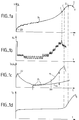
- This method uses the characteristic curve of charge voltage of a battery, for example of the cadmium-nickel type. This curve is shown in Figure 1a.
- an electronic control circuit which then decides to stop the load.
- a more recent method is to measure the temperature of the battery, and to decide to stop the load when the rate of temperature increase exceeds a certain threshold. Indeed, we see, in Figure 1d, that the temperature remains constant for almost the entire charge. It begins to increase towards the end more and more strongly, especially in the last part of the curve. With this temperature measurement method, the load is stopped at point B, at a time when the temperature increases at a speed greater than a certain rate fixed in advance.
- a disadvantage of this method is that it requires a temperature sensor on each battery, as well as one or two additional contacts to the battery-charger connection. This is sometimes prohibitively expensive.
- a second drawback of this method is that the temperature propagates slowly from the core of the battery to its periphery and then to the sensor. In other words, when the charge is stopped, the battery has already had time to overheat.
- the object of the invention is to remedy the drawbacks mentioned by proposing a method, and an integrated circuit implementing this method, which make it possible to stop the charges of the batteries before the time when an overload, or even an overheating, could have been detected.
- the principle of the invention resides in the monitoring of the curve of variation of charge of the battery as a function of time. In fact, it has been observed in the invention that the voltage across the terminals of the battery increases more and more quickly and then, before reaching its maximum, begins to grow less quickly. We then had the idea, rather than using the actual voltage signal, to use a derivative, a variation, of this voltage signal. As long as this derivative, this variation, increases from one period to the next, we are in a situation without risk for the battery.
- the invention also relates to an integrated circuit provided with circuits and connections for measuring and controlling the rapid charge of a battery, comprising a microprocessor in relation to a memory.
- program characterized in that the program contained in this memory includes instructions corresponding to the steps of the method.
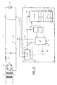
- FIG. 2 shows an integrated circuit 1 usable for implementing the method of the invention in order to charge a battery 2 from a current source 3.
- the current source 3 is represented here in a schematic manner with a transformer 4, a rectifier bridge 5 and a filter 6.
- Figure 4 will show a preferred variant embodiment of a circuit delivering a strong and constant load current.
- the battery 2 is connected by connections 7 and 8 to the charging circuit 3.
- the charging voltage of the battery is measured periodically with an analog to digital converter 9 during charging.
- This voltage is taken for example by connecting the analog digital converter 9 to connections 7 and 8.
- the analog digital converter 9 produces a measurement signal in binary mode available on its outputs 10 to 11.
- the outputs 10 to 11 of the analog digital converter 9 are connected by a bus 12 of the integrated circuit to a microprocessor 13 which manages the measurements and which produces a signal for stopping the load when the load is nominal.
- This signal for stopping the charge is for example a logic level available on a connection 14 at the output of the microprocessor 13 and terminating on a passing transistor 15 interposed in one of the connections 7 or 8. It is possible to adopt other load stop circuits: the one shown is only shown for information.
- the rectifier 5 can be a rectifier controlled by the microprocessor 13, in which case this rectifier 5 can, when the time comes, be invalidated.
- the microprocessor 13 is related to a program memory 16 of the non-volatile type (ROM). This memory 16 contains the instructions corresponding to the execution of the steps of the method. When the assembly is powered up, the microprocessor 13 can transfer the instructions contained in the memory 16 into a working memory 17 of the random access type also connected to the microprocessor 13. Depending on the type of microprocessor used, it can also be it is possible to execute the instructions read directly from the non-volatile memory 16.
- the volatile random access memory 17 also includes a set of registers which can be used to store the values of the working variables produced in the different phases of the process.
- the microprocessor 13 can finally be connected to an alarm circuit 18 comprising for example a lamp or a loudspeaker.
- the microprocessor 13 receives a clock signal H and also transmits, on a control bus 19, orders to the memories 16 and 17 and the analog-to-digital converter 9.
- the timing of the sampling carried out by the analog to digital converter 9 is caused by the microprocessor 13. In one example, this timing is of the order of one measurement per second.
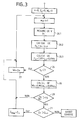
- the analog-to-digital converter 9 samples the measurement of the voltage V in step 20.1 and produces a first digitized measurement signal Y n .
- a derivative or pseudo derivative d n Y n - Y nk is calculated from Y n .
- the signal d n called the second signal, is shown in Figure 1b.
- the signal d n which represents the variation of the battery voltage, undergoes staircase steps which are due to the quantification of the analog-to-digital converter 9. This signal is not easily exploitable given its erratic nature. However, one could imagine using it as to locate its maximum corresponding to the inflection point I in Figure 1a. It would suffice to identify the instant when this signal d n would become greater than a predetermined threshold.
- the constant k is for example fixed at 10.
- the second signal thus produced, d n is representative of the variation of the charging voltage during a period.
- the duration of this period is k samples. It is not exactly a derivative, but a simple approximation which has the advantage of being easily calculated by the microprocessor 13 taking into account that there is only one subtraction to do.
- a division by k is omitted since k is constant throughout the process.
- the value k can be chosen according to the type of batteries to be charged.
- the last k measured samples Y n to Y nk will be permanently stored in memory 17.
- a new sample is measured, it takes the place of the last sample Y n measured, this takes the place of the sample Y n-1 , and so on, the old disappearing sample Y nk .
- This is represented diagrammatically in FIG. 2 by arrows for shifting the content of the registers of the memory 17. In practice, this can be done differently by simply modifying the addresses of the useful registers.
- the signal dn is noisy due to the quantization in the analog-to-digital converter 9.
- the quantization problems are solved by smoothing the derivative to obtain a smooth derivative which is more easily exploitable.
- This smoothing corresponds to a damping applied to the quantized signal dn so as to produce a third signal z n shown in Figure 1c.
- This method gives a smoothing by calculation of the average of the derivative dn.
- the triggering thus described of the stop of the charge is automatic when one is in the significant right part of the curve of the voltage V.
- a problem can arise which consists in distinguishing the top of the smoothed derivative Z n , corresponding to the point C, on the one hand a vertex 22 located at the very beginning of the curve and on the other hand many other local maximums 25 located in the middle part of the curve.
- the vertex 22 located at the start of the curve is created by the conditions of initialization of the variables at zero at the start of the charge and by a decrease in the slope of the battery voltage at the start of the charge. In fact, during the first seconds of connection, the voltage across the battery rises very quickly: rise 23 Figure 1a. Then it goes back down, causing the summit 22 of the derivative to pass.
- the local maximums 25 are themselves consecutive to the quantification of the analog-digital converter 9 in an area where the slope of the curve of the charging voltage is constant, area 24 in FIG. 1a.
- a test 26 carried out after step 20.3, it is ensured that the duration since the start of the charge is greater than a basic duration T.
- the basic duration T will be equal to one hundred seconds: equal to one hundred times the duration which separates two successive samples.
- step 28 the calculation of the variable w n is undertaken as indicated in step 28, making sure that w n is equal to 0.996 w n-1 + 0.004 z not
- step 27 This amounts to filtering the value of the derivative over approximately one thousand samples (while keeping only k samples in memory).
- step 27 makes it possible to arbitrarily fix the highly damped derivative w n quickly, at a significant value without having to wait for it to go up there.
- step 29 This comparison is undertaken in the form of a report.
- test 29 will be considered negative and the load will be allowed to continue. We retained fifty percent but obviously we could retain another report, for example twenty five percent or even possibly seventy or eighty percent. If necessary we could use this test, to stop charging.
- test 29 As soon as the result of test 29 becomes positive, we are in the significant measurement phase and we can, by carrying out test 21, locate the maximum value z n .
- test 29 When the test 29 is positive, it is considered that the battery voltage has entered a phase of rapid increase in its slope. This only occurs in this area of the charge curve, regardless of the type of battery. This makes it possible to isolate the period, located to the right of a duration XX from which the smoothed derivative z n no longer has local maxima or other singularities. It is therefore easy from this point to detect the vertex of this smoothed derivative.
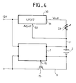
- FIG. 3 shows a preferred embodiment of such a current source stable over time and independent of the variation of the supply voltage.
- a voltage stabilized supply not shown, supplies the integrated circuit 1 at 12 volts, as well as a circuit 30, of the LM 317 type from SGS THIOMSON MICROELECTRONICS.
- This circuit 30 has two outputs 31 and 32, called Vout and Adjust, between which a setting resistor 33 can be put in parallel.
- the resistor 33 makes it possible to impose on battery 2 a voltage available at output 32 and an equal current to the ratio of the voltage difference between outputs 31 and 32 by the value of resistor 33.
Landscapes
- Engineering & Computer Science (AREA)
- Power Engineering (AREA)
- Charge And Discharge Circuits For Batteries Or The Like (AREA)
- Secondary Cells (AREA)
Applications Claiming Priority (2)
| Application Number | Priority Date | Filing Date | Title |
|---|---|---|---|
| FR9303153A FR2702884B1 (fr) | 1993-03-18 | 1993-03-18 | Procédé de charge rapide d'une batterie et circuit intégré pour la mise en Óoeuvre de ce procédé. |
| FR9303153 | 1993-03-18 |
Publications (2)
| Publication Number | Publication Date |
|---|---|
| EP0616411A1 true EP0616411A1 (de) | 1994-09-21 |
| EP0616411B1 EP0616411B1 (de) | 1996-03-13 |
Family
ID=9445123
Family Applications (1)
| Application Number | Title | Priority Date | Filing Date |
|---|---|---|---|
| EP94400575A Expired - Lifetime EP0616411B1 (de) | 1993-03-18 | 1994-03-16 | Schnelladeverfahren für Batterie und integrierter Schaltkreis zur Durchführung des Verfahrens |
Country Status (5)
| Country | Link |
|---|---|
| US (1) | US5612607A (de) |
| EP (1) | EP0616411B1 (de) |
| JP (1) | JPH06351169A (de) |
| DE (1) | DE69400088T2 (de) |
| FR (1) | FR2702884B1 (de) |
Cited By (3)
| Publication number | Priority date | Publication date | Assignee | Title |
|---|---|---|---|---|
| GB2292828A (en) * | 1994-08-29 | 1996-03-06 | Andrew Corp | Charging rechargeable batteries for portable cellular telephones utilising battery output voltage to initiate and end fast charging |
| WO2007004098A1 (en) * | 2005-06-30 | 2007-01-11 | Koninklijke Philips Electronics N.V. | Method and charger for boost charging a chargeable battery on the basis of a physical model |
| CN100392942C (zh) * | 2005-10-31 | 2008-06-04 | 中兴通讯股份有限公司 | 一种对电池充电过程进行控制的装置及方法 |
Families Citing this family (10)
| Publication number | Priority date | Publication date | Assignee | Title |
|---|---|---|---|---|
| KR100265709B1 (ko) * | 1996-10-15 | 2000-09-15 | 윤종용 | 2차 배터리 충전 장치 |
| US5770938A (en) * | 1996-12-09 | 1998-06-23 | Industrial Technology Research Institute | Real time charging control of a fast battery charger |
| US6222343B1 (en) | 1998-08-14 | 2001-04-24 | Milwaukee Electric Tool Corporation | Battery charger, a method for charging a battery, and a software program for operating the battery charger |
| US7336054B2 (en) * | 1998-08-14 | 2008-02-26 | Milwaukee Electric Tool Corporation | Apparatus and method of activating a microcontroller |
| JP2002044879A (ja) * | 2000-07-21 | 2002-02-08 | Honda Motor Co Ltd | 二次電池の充電方法および装置 |
| US20060113956A1 (en) * | 2003-05-07 | 2006-06-01 | Bublitz Scott D | Battery charger and assembly |
| AU2007325229A1 (en) * | 2006-11-27 | 2008-06-05 | Universal Supercapacitors Llc | Method of charging double electric layer electrochemical capacitors |
| DE102007051052A1 (de) * | 2007-10-16 | 2009-04-23 | C. & E. Fein Gmbh | Verfahren zum Laden von wiederaufladbaren Lithium-Akkumulatoren, Ladegerät und Lithium-Akkumulator |
| US9229502B2 (en) * | 2012-04-05 | 2016-01-05 | Apple Inc. | Fast wake-up of differential receivers using common mode decoupling capacitors |
| US10164450B2 (en) * | 2015-08-17 | 2018-12-25 | Ford Global Technologies, Llc | Early alert of battery thermal state based on voltage |
Citations (4)
| Publication number | Priority date | Publication date | Assignee | Title |
|---|---|---|---|---|
| EP0005841A2 (de) * | 1978-05-31 | 1979-12-12 | Black & Decker Inc. | Verfahren zum Laden eines Akkumulators und Vorrichtung für dieses Verfahren |
| US4503378A (en) * | 1983-05-02 | 1985-03-05 | General Motors Corporation | Charging system for nickel-zinc batteries |
| EP0444617A2 (de) * | 1990-02-28 | 1991-09-04 | Hitachi Maxell Ltd. | Verfahren zum Laden einer Sekundärbatterie |
| EP0493226A1 (de) * | 1990-12-21 | 1992-07-01 | Societe Generale De Travaux Electriques | Verfahren und Vorrichtung zum Laden einer Batterie |
Family Cites Families (1)
| Publication number | Priority date | Publication date | Assignee | Title |
|---|---|---|---|---|
| US4746852A (en) * | 1984-10-29 | 1988-05-24 | Christie Electric Corp. | Controller for battery charger |
-
1993
- 1993-03-18 FR FR9303153A patent/FR2702884B1/fr not_active Expired - Fee Related
-
1994
- 1994-03-16 EP EP94400575A patent/EP0616411B1/de not_active Expired - Lifetime
- 1994-03-16 DE DE69400088T patent/DE69400088T2/de not_active Expired - Fee Related
- 1994-03-18 US US08/210,701 patent/US5612607A/en not_active Expired - Fee Related
- 1994-03-18 JP JP6073886A patent/JPH06351169A/ja not_active Withdrawn
Patent Citations (4)
| Publication number | Priority date | Publication date | Assignee | Title |
|---|---|---|---|---|
| EP0005841A2 (de) * | 1978-05-31 | 1979-12-12 | Black & Decker Inc. | Verfahren zum Laden eines Akkumulators und Vorrichtung für dieses Verfahren |
| US4503378A (en) * | 1983-05-02 | 1985-03-05 | General Motors Corporation | Charging system for nickel-zinc batteries |
| EP0444617A2 (de) * | 1990-02-28 | 1991-09-04 | Hitachi Maxell Ltd. | Verfahren zum Laden einer Sekundärbatterie |
| EP0493226A1 (de) * | 1990-12-21 | 1992-07-01 | Societe Generale De Travaux Electriques | Verfahren und Vorrichtung zum Laden einer Batterie |
Cited By (5)
| Publication number | Priority date | Publication date | Assignee | Title |
|---|---|---|---|---|
| GB2292828A (en) * | 1994-08-29 | 1996-03-06 | Andrew Corp | Charging rechargeable batteries for portable cellular telephones utilising battery output voltage to initiate and end fast charging |
| US5640079A (en) * | 1994-08-29 | 1997-06-17 | Andrew Corporation | Battery charger for portable rechargeable batteries |
| GB2292828B (en) * | 1994-08-29 | 1997-11-05 | Andrew Corp | Method and system for charging portable rechargeable batteries |
| WO2007004098A1 (en) * | 2005-06-30 | 2007-01-11 | Koninklijke Philips Electronics N.V. | Method and charger for boost charging a chargeable battery on the basis of a physical model |
| CN100392942C (zh) * | 2005-10-31 | 2008-06-04 | 中兴通讯股份有限公司 | 一种对电池充电过程进行控制的装置及方法 |
Also Published As
| Publication number | Publication date |
|---|---|
| EP0616411B1 (de) | 1996-03-13 |
| JPH06351169A (ja) | 1994-12-22 |
| US5612607A (en) | 1997-03-18 |
| FR2702884A1 (fr) | 1994-09-23 |
| DE69400088T2 (de) | 1996-08-22 |
| DE69400088D1 (de) | 1996-04-18 |
| FR2702884B1 (fr) | 1995-04-28 |
Similar Documents
| Publication | Publication Date | Title |
|---|---|---|
| EP0616411B1 (de) | Schnelladeverfahren für Batterie und integrierter Schaltkreis zur Durchführung des Verfahrens | |
| FR2897945A1 (fr) | Dispositif destine a calculer une quantite indiquant l'etat charge d'une batterie installee sur un vehicule | |
| CA2546891C (fr) | Procede de chargement equilibre d'une batterie lithium-ion ou lithium polymere | |
| CA2594826C (fr) | Procede de chargement equilibre d'une batterie lithium-ion ou lithium polymere | |
| FR2841385A1 (fr) | Dispositif de calcul du degre de deterioration et procede de calcul du degre de deterioration d'une batterie | |
| FR2884928A1 (fr) | Procede et dispositif de detection de l'etat charge d'une batterie d'accumulateurs fondes sur un calcul de reseau neuronal | |
| EP3104143B1 (de) | System, das eine fotovoltaikzelle und eine messvorrichtung der lichtintensität umfasst, sowie verfahren zur messung der lichtintensität, die bei dieser fotovoltaikzelle eingeht | |
| FR2803105A1 (fr) | Procede de charge rapide d'une batterie d'accumulateurs | |
| EP3371544B1 (de) | Zündverfahren für einen elektronischen zünder und elektronischen zünder | |
| FR2605415A1 (fr) | Appareil de controle de l'etat de charge d'une pile | |
| FR2486243A1 (fr) | Procede et appareil pour detecter la presence d'une substance sur la surface d'un liquide | |
| EP0313460A1 (de) | Analog-Digitalwandler mit hoher Dynamik | |
| FR2977678A1 (fr) | Procede de diagnostic d'une batterie | |
| FR2747860A1 (fr) | Procede de regulation par traitement numerique du courant d'excitation d'un alternateur de vehicule automobile et dispositif regulateur mettant en oeuvre un tel procede | |
| FR2826125A1 (fr) | Procede et dispositif de controle de l'etat de charge d'un batterie, en particulier une batterie rechargeable pour un telephone mobile cellulaire | |
| WO1981002066A1 (fr) | Procede de mesure de l'etat de charge d'un accumulateur et dispositif pour la mise en oeuvre de ce procede | |
| EP3729118B1 (de) | Verfahren zur bestimmung einer folge von entladungsströmen, die bei einer gegebenen temperatur auf eine lithium-ionen-zelle anwendbar sind | |
| EP0596789A1 (de) | Verfahren und Vorrichtung zum Messen der Ladung einer Akkumulatorenbatterie | |
| FR2673468A1 (fr) | Circuit de conditionnement de signaux pour sonde a declenchement. | |
| FR2670953A1 (fr) | Procede et dispositif pour charger un accumulateur. | |
| EP1336857B1 (de) | Anordnung zur Bestimmung des Ladezustands einer Batterie, insbesondere zur Verwendung in einem Kraftfahrzeug | |
| FR2766991A1 (fr) | Procede pour la regulation par traitement numerique du courant d'excitation d'un alternateur de vehicule automobile et dispositif regulateur mettant en oeuvre un tel procede | |
| EP0240402A1 (de) | Verfahren und Einrichtung zur Sendung elektrischen Stromes mit einem Transistor in eine Schaltung | |
| EP0159263B1 (de) | Verfahren und Vorrichtung zur Kontrolle des Flüssigkeitsstandes in einem Tank | |
| EP3650875B1 (de) | Verfahren zum testen von einer elektrischen schutzeinrichtung und elektrische schutzeinrichtung, die ein solches verfahren durchführt |
Legal Events
| Date | Code | Title | Description |
|---|---|---|---|
| PUAI | Public reference made under article 153(3) epc to a published international application that has entered the european phase |
Free format text: ORIGINAL CODE: 0009012 |
|
| 17P | Request for examination filed |
Effective date: 19940527 |
|
| AK | Designated contracting states |
Kind code of ref document: A1 Designated state(s): DE FR GB IT |
|
| 17Q | First examination report despatched |
Effective date: 19941215 |
|
| GRAA | (expected) grant |
Free format text: ORIGINAL CODE: 0009210 |
|
| AK | Designated contracting states |
Kind code of ref document: B1 Designated state(s): DE FR GB IT |
|
| REF | Corresponds to: |
Ref document number: 69400088 Country of ref document: DE Date of ref document: 19960418 |
|
| GBT | Gb: translation of ep patent filed (gb section 77(6)(a)/1977) |
Effective date: 19960401 |
|
| ITF | It: translation for a ep patent filed | ||
| PLBE | No opposition filed within time limit |
Free format text: ORIGINAL CODE: 0009261 |
|
| STAA | Information on the status of an ep patent application or granted ep patent |
Free format text: STATUS: NO OPPOSITION FILED WITHIN TIME LIMIT |
|
| 26N | No opposition filed | ||
| REG | Reference to a national code |
Ref country code: GB Ref legal event code: IF02 |
|
| PGFP | Annual fee paid to national office [announced via postgrant information from national office to epo] |
Ref country code: DE Payment date: 20030327 Year of fee payment: 10 |
|
| PG25 | Lapsed in a contracting state [announced via postgrant information from national office to epo] |
Ref country code: DE Free format text: LAPSE BECAUSE OF NON-PAYMENT OF DUE FEES Effective date: 20041001 |
|
| PGFP | Annual fee paid to national office [announced via postgrant information from national office to epo] |
Ref country code: FR Payment date: 20050308 Year of fee payment: 12 |
|
| PG25 | Lapsed in a contracting state [announced via postgrant information from national office to epo] |
Ref country code: IT Free format text: LAPSE BECAUSE OF NON-PAYMENT OF DUE FEES;WARNING: LAPSES OF ITALIAN PATENTS WITH EFFECTIVE DATE BEFORE 2007 MAY HAVE OCCURRED AT ANY TIME BEFORE 2007. THE CORRECT EFFECTIVE DATE MAY BE DIFFERENT FROM THE ONE RECORDED. Effective date: 20050316 |
|
| PGFP | Annual fee paid to national office [announced via postgrant information from national office to epo] |
Ref country code: GB Payment date: 20050316 Year of fee payment: 12 |
|
| PG25 | Lapsed in a contracting state [announced via postgrant information from national office to epo] |
Ref country code: GB Free format text: LAPSE BECAUSE OF NON-PAYMENT OF DUE FEES Effective date: 20060316 |
|
| GBPC | Gb: european patent ceased through non-payment of renewal fee |
Effective date: 20060316 |
|
| REG | Reference to a national code |
Ref country code: FR Ref legal event code: ST Effective date: 20061130 |
|
| PG25 | Lapsed in a contracting state [announced via postgrant information from national office to epo] |
Ref country code: FR Free format text: LAPSE BECAUSE OF NON-PAYMENT OF DUE FEES Effective date: 20060331 |