EP0616445A1 - Duplexmehrträgerbinäre Funkübertragungsanordnung, entsprechende Mobile- und Feststation - Google Patents
Duplexmehrträgerbinäre Funkübertragungsanordnung, entsprechende Mobile- und Feststation Download PDFInfo
- Publication number
- EP0616445A1 EP0616445A1 EP94460008A EP94460008A EP0616445A1 EP 0616445 A1 EP0616445 A1 EP 0616445A1 EP 94460008 A EP94460008 A EP 94460008A EP 94460008 A EP94460008 A EP 94460008A EP 0616445 A1 EP0616445 A1 EP 0616445A1
- Authority
- EP
- European Patent Office
- Prior art keywords
- base station
- data
- signal
- terminals
- transmission
- Prior art date
- Legal status (The legal status is an assumption and is not a legal conclusion. Google has not performed a legal analysis and makes no representation as to the accuracy of the status listed.)
- Granted
Links
- 238000004891 communication Methods 0.000 title abstract description 29
- 230000005540 biological transmission Effects 0.000 claims description 60
- 230000008901 benefit Effects 0.000 description 17
- 238000000034 method Methods 0.000 description 15
- 239000000969 carrier Substances 0.000 description 12
- 230000001413 cellular effect Effects 0.000 description 9
- 238000001228 spectrum Methods 0.000 description 9
- 230000001934 delay Effects 0.000 description 8
- 238000002592 echocardiography Methods 0.000 description 8
- 238000005562 fading Methods 0.000 description 7
- 230000002457 bidirectional effect Effects 0.000 description 6
- 230000009466 transformation Effects 0.000 description 6
- 230000004044 response Effects 0.000 description 5
- 238000013459 approach Methods 0.000 description 4
- 230000000873 masking effect Effects 0.000 description 4
- 230000017105 transposition Effects 0.000 description 4
- 238000004458 analytical method Methods 0.000 description 3
- 238000010586 diagram Methods 0.000 description 3
- 230000000694 effects Effects 0.000 description 3
- 235000021183 entrée Nutrition 0.000 description 3
- 230000008569 process Effects 0.000 description 3
- 238000007476 Maximum Likelihood Methods 0.000 description 2
- 230000001427 coherent effect Effects 0.000 description 2
- 238000010276 construction Methods 0.000 description 2
- 238000012217 deletion Methods 0.000 description 2
- 230000037430 deletion Effects 0.000 description 2
- 238000012545 processing Methods 0.000 description 2
- 230000002238 attenuated effect Effects 0.000 description 1
- 238000013475 authorization Methods 0.000 description 1
- 230000008859 change Effects 0.000 description 1
- 238000006243 chemical reaction Methods 0.000 description 1
- 238000001724 coherent Stokes Raman spectroscopy Methods 0.000 description 1
- 230000003111 delayed effect Effects 0.000 description 1
- 230000001419 dependent effect Effects 0.000 description 1
- 238000009792 diffusion process Methods 0.000 description 1
- 238000010494 dissociation reaction Methods 0.000 description 1
- 230000005593 dissociations Effects 0.000 description 1
- 230000008030 elimination Effects 0.000 description 1
- 238000003379 elimination reaction Methods 0.000 description 1
- 230000001747 exhibiting effect Effects 0.000 description 1
- 239000000284 extract Substances 0.000 description 1
- 238000001914 filtration Methods 0.000 description 1
- 230000000670 limiting effect Effects 0.000 description 1
- 230000007246 mechanism Effects 0.000 description 1
- 239000003607 modifier Substances 0.000 description 1
- 230000003287 optical effect Effects 0.000 description 1
- 238000005457 optimization Methods 0.000 description 1
- 244000045947 parasite Species 0.000 description 1
- 230000036961 partial effect Effects 0.000 description 1
- 230000002093 peripheral effect Effects 0.000 description 1
- 230000002829 reductive effect Effects 0.000 description 1
- 230000002441 reversible effect Effects 0.000 description 1
- 238000000926 separation method Methods 0.000 description 1
- 230000008054 signal transmission Effects 0.000 description 1
- 230000005236 sound signal Effects 0.000 description 1
- 238000010183 spectrum analysis Methods 0.000 description 1
- 230000007480 spreading Effects 0.000 description 1
- 206010042772 syncope Diseases 0.000 description 1
Images



Classifications
-
- H—ELECTRICITY
- H04—ELECTRIC COMMUNICATION TECHNIQUE
- H04B—TRANSMISSION
- H04B7/00—Radio transmission systems, i.e. using radiation field
- H04B7/24—Radio transmission systems, i.e. using radiation field for communication between two or more posts
- H04B7/26—Radio transmission systems, i.e. using radiation field for communication between two or more posts at least one of which is mobile
- H04B7/2621—Radio transmission systems, i.e. using radiation field for communication between two or more posts at least one of which is mobile using frequency division multiple access [FDMA]
-
- H—ELECTRICITY
- H04—ELECTRIC COMMUNICATION TECHNIQUE
- H04L—TRANSMISSION OF DIGITAL INFORMATION, e.g. TELEGRAPHIC COMMUNICATION
- H04L27/00—Modulated-carrier systems
- H04L27/26—Systems using multi-frequency codes
- H04L27/2601—Multicarrier modulation systems
- H04L27/2602—Signal structure
Definitions
- the field of the invention is that of digital radiocommunication between geographically distinct transmitting and receiving stations. More specifically, the invention relates to a radiocommunication system in which a base station can manage data exchanges over the air with several remote stations, and in particular mobile stations.
- the GSM system is based on a cellular approach: the geographic territory to be covered in small portions, or cells, each served by one or more base stations. This division into cells makes it possible to optimize the use of the radio spectrum, several cells being able to use the same portion of spectrum.
- Each base station can communicate over the air with a plurality of mobiles circulating in its cell. Furthermore, the base stations are linked to a switching center which provides connections between a mobile and a remote terminal (which is for example a subscriber to the switched network or another mobile).
- the communications managed by a base station are distributed over frequency channels (traffic channels). Each traffic channel is then shared in time multiplex by several mobile stations.
- a frequency hopping management algorithm between the various frequency channels makes it possible to improve the robustness of the system with respect to the phenomenon of fading ("fading", in English).
- This phenomenon of fading is indeed a crucial problem, especially in urban areas. More precisely, we know that under conditions of multi-propagation (a station receiving simultaneously several fields coming from the same transmitter) there can occur selective fading (Rayleigh process).
- the frequency hopping technique makes it possible to limit the effects of these fades, by regularly changing the transmission frequency.
- this technique has a major drawback, namely the complexity of the stations, and in particular of the mobile stations, these having to permanently modify the modulation and demodulation frequencies, with all the constraints of tuning that this can pose.
- the invention particularly aims to overcome these drawbacks of the state of the art.
- an objective of the present invention is to provide a digital radiocommunication system exhibiting good robustness with respect to poor transmission conditions.
- the invention aims to provide such a system capable of operating in the presence of multi-jets, interference, fading, ...
- Another object of the invention is to provide such a system, in which the speed / bandwidth ratio is optimized.
- the invention also aims to provide such a radiocommunication system, in which the network layout engineering is simplified, in particular as regards the location of the antennas of the base stations.
- a particular objective of the invention is also to provide such a system in which the geographic coverage of a base station can be easily modified over time, for example as a function of the evolution of its environment.
- the invention is based on the use of a COFDM modulation (Coded Orthogonal Frequency Division Multiplex (Multiplexing of Orthogonal Coded Frequencies)) in both directions of transmission, from a mobile station to a base station (uplink) and from a base station to a mobile station (downlink).
- COFDM modulation Coded Orthogonal Frequency Division Multiplex (Multiplexing of Orthogonal Coded Frequencies)
- the COFDM technique is already known in the field of digital broadcasting.
- it has the advantage, in addition to a very good robustness with respect to various disturbances, and in particular multi-routes, to allow the coverage of a large geographic territory by using a plurality of transmitters operating at a single modulation frequency. (single frequency network).
- the invention shows that, however, the COFDM is entirely usable in a radiocommunication system.
- said signal received by said base station is organized in successive frames each comprising a predetermined number of first data symbols, each frame being divided into time intervals each comprising at least one data symbol, and it is assigned to each of said mobiles at least one time interval, said mobile transmitting data only during the time intervals assigned to it.
- TDMA time division multiple access
- said signal from each of said base stations comprises synchronization data
- each of said mobiles comprises means for controlling the instant of transmission of said first symbols, as a function of said synchronization data.
- a guard interval is provided between each of said first data symbols, so as to absorb the synchronization differences between two mobile stations.
- Such a guard interval has already been proposed to avoid phenomena of intersymbol interference. According to the invention, it responds to another problem, namely the synchronization differences which may appear between two mobile stations (seen from the base station), for example because one of the mobile stations is close to an antenna, and the other distant (different transmission times).
- said second channel coding means perform a time and frequency interleaving of said data elements of said second source signal
- said first channel coding means perform a frequency only interleaving of said data elements of said first source signal
- the coding used is not the same in the two directions of transmission (unlike known radiocommunication systems).
- this coding is adapted to the particularities of each direction of transmission.
- due to the time distribution in the uplink direction there is no time interleaving. It is therefore not necessary, to carry out the decoding, to combine the data contained in several successive time intervals.
- each of said time intervals comprises a series of at least two first consecutive data symbols, and the first symbol of said series is a demodulation reference symbol, making it possible to perform in a base station a differential demodulation of the following symbols of said series.
- each mobile station it is indeed necessary for each mobile station to provide its own demodulation reference, in the case of differential demodulation. It is also possible to implement, in at least one of the directions of transmission, a coherent demodulation.
- said transmission and reception terminals are located so that the transmission times of a signal between each of said terminals and the associated base station are different.
- transmission times may depend on the location of the terminals (transmission time between the terminal and the base station) and / or on the use of different delays (possibly variable in time) for each terminal.
- the difference between two of said transmission times is greater than the inverse of the bandwidth of the signal transmitted by said mobile stations.
- the applied delay is greater than the time resolution capacity of the base station, which guarantees the dissociation of the energies coming from the different antennas.
- each base station is linked to a switching center (possibly via one or more intermediate levels, forming a tree network) which provides the necessary connections.
- the invention is not limited solely to radiotelephony to mobiles. Indeed, the good robustness and the high throughput offered by the COFDM technique make it possible to transmit data and / or images. Many computer, telematics, multimedia applications can therefore be envisaged.
- mobile station is used here to simplify the understanding of the invention, compared with known systems (GSM for example), but should not be limited strictly speaking to movable (“mobile”) terminals. They can also be fixed elements, or simply capable of being moved.
- the invention makes it possible to implement local networks, in which a base station controls (over the air) several telephone and / or computer terminals.
- the establishment of a such a network is particularly simple (absence of cabling), and this network is easily upgradeable (addition or deletion of a terminal).
- the invention therefore relates to a new radiocommunication system with mobiles, implementing multicarrier modulation in both directions of communication.
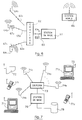
- Figure 1 shows an example of implementation of a cellular radio network according to the invention.
- the main characteristic of the invention is to associate with each base station (that is to say, in the case of a cellular network, with each cell) a plurality transmission / reception terminals.
- This new approach makes it possible, on the one hand, to take advantage of the advantages of single-frequency multi-carrier systems, and on the other hand to simplify the establishment and management of a network infrastructure.
- Each terminal of the same cell operates at the same transmit and receive frequencies.
- two neighboring cells use different frequencies.
- a first important characteristic of the invention appears directly from the view in FIG. 1 the shape and size of cells 11 1 to 11 4 can be any, and different from one cell to another.
- each cell comprises only a single antenna.
- the shape of the cells is therefore imposed: it is necessary that the perimeter thereof is substantially the same distance from a central point (the antenna).
- the cells should ideally be circular, and are in practice hexagonal (in the case of GSM).
- the shape can be arbitrary, and for example rectangular (cells 11 and 11 4 ). It is thus possible to adapt the shape of the cells as a function of needs and constraints, by appropriately placing the terminals 13 1 , 1 to 13 1.7 .
- Cell 11 1 has the form of the union (in the mathematical sense) of all of the covers 14 1.1 to 14 1.7 .
- cell 11 1 could be extended on its left by adding terminals 13 1 , 1 and 13 1.2 (case of the extension of a new district, the construction of a new road ... ).
- This flexibility is enabled by an essential characteristic of COFDM coding, which makes it possible to take advantage of multiple paths. This makes it possible, when viewed from mobiles, to create monofrequency broadcasting networks, that is to say networks comprising co-channel transmitters all transmitting on the same modulation frequency, each transmitter being seen as an echo.
- the mobile station (SM) 151.1 receives the contributions 16 1 and 16 2 and 16 3 from the terminals 13 1.1 and 13 1.2 and 13 1 , 3 respectively.
- the base station 12 1 receives signals transmitted by the mobile station 15 1,1 via the three terminals 13 1,1 and 13 1 , 2 and 13 1.3 .
- the base station 12 1 therefore forms in the uplink direction a receiver with spatial diversity (several distributed reception antennas). Again, we thus benefit from the echoes produced by the various contributions 17 1 and 17 2 and 17 3 .
- This characteristic also makes it possible to eliminate the gray areas in the cover of a cell. For example, if the zone 14 1 , 7 is not covered, a terminal 13 1 , 7 can be added, to remove the shadow zone. It should be noted that this addition can be made at any time, and for example when a new building has been constructed, masking zone 14 1.7 .
- each base station can manage a predefined number of communications.
- a high population density for example the center of a city
- the surface area of the cells may be increased (depending on the probability of the number of simultaneous calls).
- the system described above allows first of all to establish communications between two mobiles 15 1,1 and 15 1,2 circulating in the same cell 11 1 .
- This case also corresponds to the simplified embodiment where there is only one base station, and therefore only one cell (case of a network simply covering a city or a private site).
- the communication is then directly managed by the base station 12 1 . (It can also pass through switch 18, as in the following case).
- the network thus formed may include a tree structure on several levels, as well as GSM (each base station being connected to a base station controller, itself connected to a switching center).
- Communications can also be established, via the switch 18, with any other type of terminal 110 (telephone on the switched network, computer center, computer terminal, fax machine, etc.).
- FIG. 2 illustrates the transmission chain in the downward direction, that is to say from a base station 12, to a mobile station 15 1,1 .
- This chain of transmission is similar to that implemented in the case of COFDM broadcasting already known. However, it is recalled below, by way of example (other types of coding which can of course be implemented), the essential characteristics.
- COFDM Coded Orthogonal Frequency Division Multiplex
- the first principle is the distribution of the information to be transmitted over a large number of modulated carriers each at a low bit rate, in order to reduce the selectivity effect of the transmission channel (COFDM signal).
- the second principle of the COFDM system consists in correlating by a coding process consecutive information elements (channel coding) and in transmitting them to points distant from the time-frequency domain (technique of interleaving in time and in frequency). The distance between these points is chosen so as to ensure statistical independence between two successive elements of a source signal.
- Channel coding implements a convolutional code.
- the channel coding aspect does not relate directly to the present invention, the principle is briefly described in order to fully present an example of a broadcasting system which can implement the method of the invention. This is of course a simple, non-limiting example.
- the actual modulation process of this known system overcomes the problems associated with the frequency selectivity of the channel. It consists in ensuring the distribution of digital elements constituting the data signal in the frequency-time space and in simultaneously transmitting sets of digital elements on a plurality of parallel broadcasting channels by means of a frequency multiplex using frequencies orthogonal carriers. In particular, this type of modulation makes it possible to avoid two successive elements of the data train being transmitted at the same frequency.
- FIG. 2 is therefore a block diagram of a transmission chain (base station 219) and reception chain (mobile station 220) of a system implementing the COFDM technique.
- the source digital data 21 to be transmitted are subject to a convolutional coding 22.
- the general principle of such a code is to associate with each source value a coded value dependent on this value source and at least one of the values preceding it. Due to the link thus created between the coded values, it is then possible, on decoding, to reconstruct the sequence of the source values even when a received coded value is false, using a maximum likelihood decoding, such than a soft decision Viterbi decoding (that is to say a decoding delivering an estimate of the value received and a weighting representative of the confidence that can be given to this estimate).
- a maximum likelihood decoding such than a soft decision Viterbi decoding (that is to say a decoding delivering an estimate of the value received and a weighting representative of the confidence that can be given to this estimate).
- an external code of the Reed-Solomon or CSRS type (Cyclotomatically Shortened Reed Solomon (cyclotomatically shortened Reed Solomon code)) can be concatenated to the convolutional code.
- the source data can of course be of any type, be it audio signals, image signals or data signals. They can moreover correspond to several sources of distinct origins, emitted simultaneously.
- the COFDM system is based on the simultaneous use of a plurality of carrier frequencies transmitted simultaneously.
- the number N of carriers can be arbitrary. It is conventionally of the order of a few hundred (it could also be of the order of a few units).
- Each of these carriers is modulated at a low flow rate (compared to the flow rate required for a corresponding single-carrier system). This reduces the selectivity effect of the channel.
- the global signal emitted is therefore a broadband signal (occupying for example a band of a few megahertz).
- This wide band is an advantage, in the case of systems designed to take advantage of multipaths, such as COFDM. Indeed, due to the spreading of the response of the transmission channel, it is very improbable that a deep fading simultaneously affects the whole of the signal.
- the spectra of the different carriers overlap each other.
- the complete signal checks certain conditions of orthogonality, allowing the separation of the information associated with the different carriers, for example by using the technique of the Fourier transformation (as it is specified further on).
- the concept of orthogonality of the carrier frequencies implies that the spectra of the carriers can overlap, provided that, when one of the spectra exhibits its maximum power, that is to say at the frequency precise of the carrier corresponding to this spectrum, all the other spectra have zero power. The decoding is therefore not disturbed if we consider this precise frequency.
- the intersymbol interference introduced in particular by the multiple paths during the transmission can disturb this orthogonality.
- a guard interval is inserted between each symbol sent. The duration of this guard interval is chosen to be greater than the spread of the impulse response of the channel.
- the coding module 22 delivers coded data elements C k 23 belonging to a modulation alphabet.
- the choice of the alphabet specifies the type of modulation used. For example, for a modulation with 4 phase states (MDP4), the alphabet used is ⁇ 1 + i, 1 - i, -1 + i, -1 - i ⁇ .
- MDP4 modulation with 4 phase states
- Many other types of modulation can be used, such as MDP8,16QAM modulations or trellis coding modulations according to the Ungerboeck method.
- the coded data elements 23 are then subjected to an operation 24 of distribution in the frequency-time space, which consists in associating with each of the carrier frequencies data elements selected in the series of coded data 23 so as to break, by mixing, the correlation of the distortions suffered by the transmitted samples.
- time-frequency space is meant a set of points distributed along two perpendicular axes, the time axis and the frequency axis. According to the frequency axis, there are as many points as there are carrier frequencies. According to the time axis, a point corresponds to the duration of a symbol.
- this distribution ensures at least that two successive source data are not transmitted consecutively and / or on the same carrier frequency. More generally, the distance in time-frequency space between two successive coded data is at a minimum such that the statistical independence between these data is ensured.
- this distribution 24 in time-frequency space can correspond to an interleaving in time 24A consisting for example of a selective application of delays of different durations, followed by an interleaving in frequencies 24 8 , consisting of a selective allocation data elements delayed at different carriers.
- this interleaving in time is, in the case of telephone communications, different from that applied in currently developed broadcasting systems (DAB (Digital Audiobroadcasting)). More precisely, the delays applied are lower, and chosen so as not to disturb the communication (due to too long a delay between transmission and reception, as is for example the case in satellite communications).
- DAB Digital Audiobroadcasting
- Each carrier frequency is then modulated by the sequence of data elements C k which is intended for it.
- This modulation operation can be performed by applying an inverse fast Fourier transformation (FFT- 1 ) 26 to the series 25 of data elements.
- FFT- 1 inverse fast Fourier transformation
- These symbols 27 are then transmitted, in a conventional manner, using a transmission module 28, which in particular performs the digital / analog conversion of the symbols 27, then a transposition of the corresponding analog signal in the radio frequency domain.
- the signal is transmitted by all of the terminals associated with the base station 119.
- the transmission channel 29 (generally having multiple paths seen from the mobile 220) is received in a reception module 210 of this mobile, also conventional.
- each symbol received (not affected by intersymbol interference) can take the form: where H k represents the response of channel 29 at the frequency f k .
- This signal 211 is subjected to a transformation (FFT) 212, symmetrical with the inverse transformation 26.
- This transformation 212 delivers the following data elements 213:
- a deinterlacing module 216 performing the reverse operations of the module 24, so as to reconstitute the original order of the symbols, which are then directed into a decoding module 217, performing a decoding with maximum a posteriori likelihood, such as a soft decision Viterbi decoding.
- a decoding module 217 performing a decoding with maximum a posteriori likelihood, such as a soft decision Viterbi decoding.
- the multiplicative factor 1 H * j, k of the previous equation is directly representative of the confidence associated with the decision.
- N j , k is a complex Gaussian noise whose each component has a variance cr2j.k.
- the decoding module thus supplies, after a possible decoding of the concatenated code, if such a code has been implemented on transmission, the signal 218 corresponding to the source signal 21.
- FIG. 3 shows, by way of example, such a structure. More specifically, FIG. 3 illustrates a frame made up of M successive symbols.
- Each frame advantageously begins with two particular symbols S1 and S2, the role of which is explained below. It then comprises a certain number of useful symbols S3 to SM, each comprising N modulated orthogonal carriers 31.
- the symbol S1 is a null symbol (no signal is emitted during the duration of this symbol), making it possible on the one hand to carry out an analog synchronization, and on the other hand to carry out the spectral analysis of the possible jammers.
- the symbol S2 is a second synchronization symbol constituted by a multiplex of all the carrier frequencies modulated by fixed symbols (wobble symbol). Among other things, it allows synchronization to be reset more precisely by analyzing the channel's impulse response. The role and the embodiment of these symbols S1 and S2 are described in patent FR 88 15216, filed on 18.11.88.
- This symbol S2 can also be used as a phase reference for the demodulation of each carrier of the following symbols, when these are differentially modulated.
- each mobile station demodulates only the symbol sequence intended for it plus the symbol which immediately precedes this sequence, (principle of differential demodulation).
- the frame can also be divided into channels (Ci, Cj) grouping together for example a predetermined number of symbols, each channel containing for example the data intended for a given mobile station, or for a group of mobile stations.
- each symbol begins with a guard interval 22, which makes it possible to eliminate losses of orthogonality due to intersymbol interference.
- One of the essential advantages of the COFDM system is that the receivers are not disturbed by the received signal echoes. On the contrary, they take advantage of it.
- this system was designed in particular to allow the reception of digital signals in mobiles, even, and in particular, in particularly hostile transmission environments, such as urban environments.
- the COFDM system works in channels affected by multiple paths, due to the presence of natural obstacles (buildings, trees, vehicles, ).
- Such channels can be modeled by a Rayleigh distribution or a Rice-Nagakami distribution (if a path predominates).
- the receivers must include means for reconstructing the digital data transmitted, compensating for the problems due to the disturbances, and in particular to the echoes induced by the transmission channel.
- this result is achieved in particular thanks to interleaving in time and in frequency (frequency diversity), in the use of convolutional coding and in the presence of a guard interval between two symbols. consecutive data.
- This advantageous characteristic also makes it possible to use single-frequency broadcasting networks, that is to say networks comprising co-channel transmitters, all transmitting on the same modulation frequency, each transmitter being seen as an echo.
- multicarrier and “single frequency”, which do not apply to the same processing phase of the signal to be transmitted.
- the multicarrier signal corresponds to the useful baseband signal, which consists of a plurality of carriers (32; fig.3) each modulated by a data element.
- This baseband signal is then transposed into the radio frequency domain (28), by multiplication by a radiofrequency transmission frequency, with a view to its transmission.
- the system is said to be single frequency because each transmitter (each terminal) uses the same transmission frequency.
- the principle of monofrequency networks amounts to generating active echoes (interpreted as natural echoes), from a set of terminals distributed over the surface of a cell.
- Figure 4 shows the data transmission chain in the uplink direction. It has many points in common with the transmission chain in the downward direction of FIG. 2, but also certain specificities, due to the fact that several mobile stations 419, at 419 K can transmit to a single base station, the latter managing several communications simultaneously.
- the reception part, in the base station 420 is entirely similar to that carried out in the mobile station 220 in FIG. 2.
- the constitution and the operation of the elements 410 to 417 are therefore not repeated. Reference will be made to the corresponding elements 210 to 217.
- the operation is modified substantially, due to the use of a TDMA distribution.
- the coded data 43 are subjected to an interleaving in frequency 44 8 . However, these data are not temporally interleaved (unlike the downlink signal).
- each mobile station 419 operating only over a short period of time see Figure 5
- interleaving time as implemented in module 24A cannot be implemented.
- a particular time interleaving can however be envisaged, but limited to the number of symbols constituting each interval of a TDMA frame.
- the data 45 interleaved in frequency is then transformed using an FFT- 1 46 (identical to the FFT- 1 26), then transmitted using the transmission module 48.
- This module 48 performs the same functions than module 28, but only during the time interval which is allocated to the mobile station considered. It is therefore controlled by synchronization means 421.
- each mobile station 419 extracts synchronization data 422.
- the synchronization means 421 deliver to the transmission module 48 transmission authorizations 423, during the transmission moments allocated to the station.
- FIG. 5 shows an example of a symbol frame as received by the base station.
- the frame is divided into time intervals (or "slots" in English) Il (SH to SL), I j (SP to SQ), each interval being allocated to a mobile station.
- each interval begins with a synchronization symbol (thus, each mobile emits its own synchronization symbol).
- This synchronization symbol can also serve as a demodulation reference (as well as the S2 symbol already described), and as a gain reference (each mobile being received by the base station with variable powers).
- the allocation of the intervals is fixed: the interval I is systematically assigned to the mobile station i.
- this mobile station knows the location of this interval in the frame (for example in the form of a delay to be applied after reception of the synchronization symbols S1 and S2).
- the synchronization data 422 therefore correspond to the symbols S1 and S2.
- this allocation is dynamic: the base station allocates intervals as required (that is to say when a call is requested). In this case, at least some of the frames sent by the base station carrying an allocation descriptor.
- a channel of this frame (formed by one or more symbols) carries this descriptor, in a known format mobile stations. It is part of the synchronization data 422 taken into account by the synchronization means 421.
- this is the first channel of the frame.
- mobile stations for which no communication is in progress can operate intermittently. They go out of standby shortly before the start of the frame (synchronization symbol), then return to standby if the descriptor channel does not carry any information concerning them.
- this descriptor can begin with an indicator for a change in allocation. As long as this indicator retains a determined value, the mobile stations know that the allocation has not changed.
- the frame received (FIG. 5) by the base station comprises a symbol (or a channel) 53 in which all of the mobile stations can transmit communication requests.
- a particular mechanism manages possible collisions between two simultaneous requests (for example by a request for repetition in the allocation descriptor, or by repetition at regular or random time intervals, until the corresponding allocation appears in the descriptor).
- Each interval I or I j can include one or more symbols. However, if a differential demodulation (414) is implemented, each interval must include at least two symbols, the first (SQ, SP) being a demodulation reference symbol known to the base station.
- mobile stations may implement partial FFT, the data elements being adequately distributed over the corresponding carrier frequencies by the base station.
- Each symbol always begins with a guard interval 52, which makes it possible to absorb intersymbol interference and the differences in transmission time between two mobile stations.
- a base station 61 (notably comprising the elements contained in blocks 219, FIG. 2 and 420, FIG. 4) is connected to a coupler 62, by a bidirectional link 63. (This coupler can also be an integral part of the base station ).
- the coupler 62 is itself connected to several bidirectional radio terminals 64 1 to 64 N , by means of as many distribution links 65 1 to 65 N.
- bidirectional links 63 and 65 1 to 65 N can for example be coaxial or optical cables, so as to form a star network, or a tree (the tree structure can possibly have several levels).
- they may be radio links.
- FIG. 8 illustrates such a situation: the base station 81 is connected to the terminals 82 1 to 82 4 by a tree-coaxial network 83. In this architecture, the coupler is distributed between the connection points 84 1 to 84 3 .
- the coupler 62 plays the conventional role of combiner, in the upward direction, and of divider, in the downward direction.
- the signal received 63 M by the base station 61 corresponds to the combination of the signals received from the mobile 66 by each of the terminals 64 1 to 64 N.
- the signal transmitted 63 D by the base station 61 is transmitted by all of the terminals 64 1 to 64 N.
- Each terminal 64 1 to 64 N conventionally comprises a bidirectional amplifier, a transmission filter and a reception filter, and a bidirectional antenna.
- a separate delay T i 67 2 to 67 N is also associated with each terminal.
- the diversity of space can, under certain conditions, pose problems.
- the components of the two signals will combine into a single component.
- the resultant is very attenuated, even null.
- the two components are considered as echoes, which a COFDM receiver can handle.
- delays 67 2 to 76 N are therefore used , as has already been presented in French patent application FR 90 11192, in the significantly different (because unidirectional) context of broadcasting.
- delays are chosen so that the difference in any two of them is greater than the resolution in time T R of the receiver: for i, j 1 [1, N], i ⁇ j) or approximately: B being the bandwidth of the transmitted signal.
- the present invention is not limited to cellular telephone radiocommunications.
- many other applications can be envisaged, in particular because the COFDM technique offers the double advantage of a high throughput and great robustness.
- Figure 7 presents such a particular application to local networks.
- a local area network makes it possible to connect a plurality of computer terminals 71 1 , 712 to one another, so that these can exchange data and / or share peripherals (printer 72, for example).
- the system of the invention makes it possible to produce such a network, without wiring (if not, possibly, that between the coupler 73 and the transmission / reception terminals 74 1 to 74 N ).
- adding a new element 71 2 to the network is very simple: it suffices to provide it with transmission / reception means 75, and to declare its existence at the base station 76.
- the system can simultaneously manage other types of communications, such as telephone communications between telephone sets 77 i , 77 2 . Again, no wiring is necessary and these stations can be moved, even during communication.
- the base station 76 controls these different communications. It can also manage the transmission of specific data (paging system, broadcasting of animated or non-animated images, etc.). It can also control a data server 78.
Landscapes
- Engineering & Computer Science (AREA)
- Computer Networks & Wireless Communication (AREA)
- Signal Processing (AREA)
- Mobile Radio Communication Systems (AREA)
Applications Claiming Priority (2)
| Application Number | Priority Date | Filing Date | Title |
|---|---|---|---|
| FR9303280 | 1993-03-17 | ||
| FR9303280A FR2702904B1 (fr) | 1993-03-17 | 1993-03-17 | Systeme de radiocommunication numerique bidirectionnel multiporteuse, station mobile et station de base correspondantes. |
Publications (2)
| Publication Number | Publication Date |
|---|---|
| EP0616445A1 true EP0616445A1 (de) | 1994-09-21 |
| EP0616445B1 EP0616445B1 (de) | 2000-05-31 |
Family
ID=9445216
Family Applications (1)
| Application Number | Title | Priority Date | Filing Date |
|---|---|---|---|
| EP94460008A Expired - Lifetime EP0616445B1 (de) | 1993-03-17 | 1994-03-17 | Duplexmehrträgerbinäre Funkübertragungsanordnung, entsprechende Mobile- und Feststation |
Country Status (3)
| Country | Link |
|---|---|
| EP (1) | EP0616445B1 (de) |
| DE (1) | DE69424705T2 (de) |
| FR (1) | FR2702904B1 (de) |
Cited By (12)
| Publication number | Priority date | Publication date | Assignee | Title |
|---|---|---|---|---|
| GB2296407A (en) * | 1994-12-22 | 1996-06-26 | Roke Manor Research | Frequency hopped cellular mobile radio system using orthogonal frequency division multiple access |
| EP0725509A1 (de) * | 1995-01-31 | 1996-08-07 | ALCATEL BELL Naamloze Vennootschap | Speziell zugeordnetes Übertragungssystem mit Frequenzmultiplex mit Mehrfachzugriff (FDMA), Sender und Empfänger in einem solchen Übertragungssystem |
| WO1996019052A3 (de) * | 1994-12-16 | 1996-08-29 | Grundig Emv | Schaltungsanordnung und verfahren zur realisierung eines rückübertragungskanals vom empfänger zum sender in einem gleichwellennetz |
| WO1997006619A1 (en) * | 1995-08-04 | 1997-02-20 | Telia Ab | Procedure to suppress near-end crosstalk at bidirectional communication in wire network |
| WO1997026720A1 (en) * | 1996-01-19 | 1997-07-24 | Pcs Wireless (Ip) Inc. | Delay insensitive basestation-to-handset interface for radio telephone systems |
| WO1999000926A3 (en) * | 1997-06-30 | 1999-03-18 | Ericsson Telefon Ab L M | A digital system for subscriber lines allowing high bit rates |
| EP0831627A3 (de) * | 1996-09-24 | 2000-01-19 | AT&T Corp. | Zuordnung von Unterträgern an eine Gruppenantenne in einem Mehrträgersender |
| US6023628A (en) * | 1992-08-05 | 2000-02-08 | Pcs Wireless, Inc. | Base stations for TDD telephony and methods for operating the same |
| EP0810753A3 (de) * | 1996-05-27 | 2001-09-05 | Sony Corporation | Übertragungs- und Empfangssystem für Mehrfachzugriff mit Multiplexierung von Mehrträgersignalen |
| US6625847B1 (en) | 1999-03-04 | 2003-09-30 | Samuel Heath & Sons Plc | Door closers |
| EP0829989A3 (de) * | 1996-08-23 | 2004-08-11 | Sony Corporation | Verfahren für die Übertragung und den Empfang von digitalen multiplizierten Mehrfrequenzsignalen, Übertragungsvorrichtung und Empfangsvorrichtung für ein solches Verfahren |
| CN101557503B (zh) * | 2009-05-19 | 2011-04-13 | 辽宁省电力有限公司抚顺供电公司 | 电力抢修应急指挥无线视频音频监控系统 |
Citations (3)
| Publication number | Priority date | Publication date | Assignee | Title |
|---|---|---|---|---|
| US4392242A (en) * | 1980-03-10 | 1983-07-05 | Nippon Electric Co., Ltd. | Mobile communication system |
| EP0499560A1 (de) * | 1991-01-17 | 1992-08-19 | France Telecom | Verfahren zur Kanalschätzung für COFDM-Übertragungssystem |
| EP0529421A2 (de) * | 1991-08-29 | 1993-03-03 | Daimler-Benz Aktiengesellschaft | Verfahren und Anordnung zur Messung der Trägerfrequenzablage in einem Mehrkanalübertragungssystem |
-
1993
- 1993-03-17 FR FR9303280A patent/FR2702904B1/fr not_active Expired - Lifetime
-
1994
- 1994-03-17 EP EP94460008A patent/EP0616445B1/de not_active Expired - Lifetime
- 1994-03-17 DE DE69424705T patent/DE69424705T2/de not_active Expired - Lifetime
Patent Citations (3)
| Publication number | Priority date | Publication date | Assignee | Title |
|---|---|---|---|---|
| US4392242A (en) * | 1980-03-10 | 1983-07-05 | Nippon Electric Co., Ltd. | Mobile communication system |
| EP0499560A1 (de) * | 1991-01-17 | 1992-08-19 | France Telecom | Verfahren zur Kanalschätzung für COFDM-Übertragungssystem |
| EP0529421A2 (de) * | 1991-08-29 | 1993-03-03 | Daimler-Benz Aktiengesellschaft | Verfahren und Anordnung zur Messung der Trägerfrequenzablage in einem Mehrkanalübertragungssystem |
Cited By (19)
| Publication number | Priority date | Publication date | Assignee | Title |
|---|---|---|---|---|
| US6023628A (en) * | 1992-08-05 | 2000-02-08 | Pcs Wireless, Inc. | Base stations for TDD telephony and methods for operating the same |
| WO1996019052A3 (de) * | 1994-12-16 | 1996-08-29 | Grundig Emv | Schaltungsanordnung und verfahren zur realisierung eines rückübertragungskanals vom empfänger zum sender in einem gleichwellennetz |
| AU702787B2 (en) * | 1994-12-16 | 1999-03-04 | Grundig Car Intermedia System Gmbh | Circuit array and method for creating a data feedback channel from receiver to transmitter in a common frequency network |
| US6178175B1 (en) | 1994-12-16 | 2001-01-23 | Grundig Ag | Circuit array and method for creating a data feedback channel from receiver to transmitter in a common frequency network |
| GB2296407A (en) * | 1994-12-22 | 1996-06-26 | Roke Manor Research | Frequency hopped cellular mobile radio system using orthogonal frequency division multiple access |
| GB2296407B (en) * | 1994-12-22 | 1999-10-06 | Roke Manor Research | Frequency hopped cellular mobile radio systems |
| EP0725509A1 (de) * | 1995-01-31 | 1996-08-07 | ALCATEL BELL Naamloze Vennootschap | Speziell zugeordnetes Übertragungssystem mit Frequenzmultiplex mit Mehrfachzugriff (FDMA), Sender und Empfänger in einem solchen Übertragungssystem |
| AU708418B2 (en) * | 1995-01-31 | 1999-08-05 | Alcatel N.V. | A transmission system |
| WO1997006619A1 (en) * | 1995-08-04 | 1997-02-20 | Telia Ab | Procedure to suppress near-end crosstalk at bidirectional communication in wire network |
| WO1997026720A1 (en) * | 1996-01-19 | 1997-07-24 | Pcs Wireless (Ip) Inc. | Delay insensitive basestation-to-handset interface for radio telephone systems |
| EP0810753A3 (de) * | 1996-05-27 | 2001-09-05 | Sony Corporation | Übertragungs- und Empfangssystem für Mehrfachzugriff mit Multiplexierung von Mehrträgersignalen |
| EP0829989A3 (de) * | 1996-08-23 | 2004-08-11 | Sony Corporation | Verfahren für die Übertragung und den Empfang von digitalen multiplizierten Mehrfrequenzsignalen, Übertragungsvorrichtung und Empfangsvorrichtung für ein solches Verfahren |
| EP0831627A3 (de) * | 1996-09-24 | 2000-01-19 | AT&T Corp. | Zuordnung von Unterträgern an eine Gruppenantenne in einem Mehrträgersender |
| US6208669B1 (en) | 1996-09-24 | 2001-03-27 | At&T Corp. | Method and apparatus for mobile data communication |
| US6404783B1 (en) | 1996-09-24 | 2002-06-11 | At&T Corp. | Method and apparatus for mobile data communication |
| WO1999000926A3 (en) * | 1997-06-30 | 1999-03-18 | Ericsson Telefon Ab L M | A digital system for subscriber lines allowing high bit rates |
| AU742816B2 (en) * | 1997-06-30 | 2002-01-10 | Telefonaktiebolaget Lm Ericsson (Publ) | A digital system for subscriber lines allowing high bit rates |
| US6625847B1 (en) | 1999-03-04 | 2003-09-30 | Samuel Heath & Sons Plc | Door closers |
| CN101557503B (zh) * | 2009-05-19 | 2011-04-13 | 辽宁省电力有限公司抚顺供电公司 | 电力抢修应急指挥无线视频音频监控系统 |
Also Published As
| Publication number | Publication date |
|---|---|
| FR2702904A1 (fr) | 1994-09-23 |
| EP0616445B1 (de) | 2000-05-31 |
| FR2702904B1 (fr) | 1995-06-30 |
| DE69424705D1 (de) | 2000-07-06 |
| DE69424705T2 (de) | 2001-02-08 |
Similar Documents
| Publication | Publication Date | Title |
|---|---|---|
| EP0095959B1 (de) | Funkverbindungssystem nach dem Frequenzsprungverfahren | |
| EP0565470B1 (de) | Verfahren zur digitalen Funknachrichtenübertragung | |
| EP0775394B1 (de) | Verfahren zur luftschnittstellenanpassung in einer mobilen funkkommunikationsanordnung | |
| FR2696602A1 (fr) | Procédé et appareil permettant l'application de sauts de fréquence à une voie de signalisation dans un système de télécommunications. | |
| FR2939005A1 (fr) | Procede d'emission de donnees et procede de reception correspondant | |
| EP0616445B1 (de) | Duplexmehrträgerbinäre Funkübertragungsanordnung, entsprechende Mobile- und Feststation | |
| FR2943882A1 (fr) | Procede d'emission pour un reseau sans fil et procede de reception correspondant | |
| EP1070401A1 (de) | Signal eines zellularen funktelefonsystems mit zusätzlichem abwärtskanal und dafür geeignetes verfahren, system, mobilstation und basisstation | |
| EP1464148B1 (de) | Kommunikationsverwaltungsverfahren in einem netzwerk, signal, vorrichtung und empfangsgerät dafür | |
| EP0641096B1 (de) | Verfahren mit mehrfachem Zugang durch Einteilung in orthogonale Frequenzen, entsprechende zentrale Station, entfernte Station, System und deren Verwendung | |
| EP1391095B1 (de) | Verfahren zur schätzung der übertragungsfunktion eines mehrträger-signalübertragungskanals und eines entsprechenden empfängers | |
| EP1770885B1 (de) | Verfahren und Vorrichtung zur automatischen Planung von Verzögerungen zwischen Sendezeiten von Sender in einem synchronen Einfrequenznetzes | |
| EP0588741B1 (de) | System zur Rundsendung von Digitalsignalen bei Zeitdiversity, entsprechende Sender und Empfänger | |
| FR2697699A1 (fr) | Dispositif de réamplification d'un signal radiofréquence, notamment pour des applications domestiques, et systèmes de réception correspondant. | |
| EP0887950A1 (de) | Basisstation mit Antennendiversity zur Übertragung von unidirektionalen Kanälen und entsprechendes Verfahren | |
| EP2446554B1 (de) | Verfahren zum senden in einem drahtlosen netzwerk, und ein entsprechendes verfahren zum empfangen | |
| EP1181786B1 (de) | Verfahren zur funkübertragung zwischen einer basisstation und mobilfunkendgeräten | |
| WO2000072472A1 (fr) | Procede de diffusion de signaux radio depuis une station de base de radiocommunication, stations de base et terminaux mobiles pour la mise en oeuvre d'un tel procede | |
| EP0767550B1 (de) | Interbandfrequenzsprungverfahren in einer zellulare Funkkommunikationsanordnung mit mobilen Stationen und Stationen dafür | |
| FR2829890A1 (fr) | Procede et systeme de diffusion d'informations sous forme numerique depuis un satellite | |
| WO2006069826A1 (fr) | Procede d'emission de signaux multiporteuses dans un reseau multicellulaire a macro-diversite planifiee, reseau, signal, procede et dispositif de reception correspondants. | |
| EP4383591B1 (de) | Verfahren zur zuweisung von zeit-frequenz-ressourcen in einem satellitenkommunikationssystem mit strahlformung, vorrichtung und computerprogramm dafür | |
| EP2524446A1 (de) | Verfahren zur übertragung eines digitalen signals für ein verteiltes system, zugehöriges programmprodukt und relaisvorrichtung | |
| EP1128590A1 (de) | Synchronisierungssystem für ein digitales telekommunikationssystem mit vielfachzugriff | |
| FR2890820A1 (fr) | Procede d'etablissement d'une couverture permettant une telediffusion numerique par reutilisation d'une meme frequence |
Legal Events
| Date | Code | Title | Description |
|---|---|---|---|
| PUAI | Public reference made under article 153(3) epc to a published international application that has entered the european phase |
Free format text: ORIGINAL CODE: 0009012 |
|
| AK | Designated contracting states |
Kind code of ref document: A1 Designated state(s): DE GB IT |
|
| 17P | Request for examination filed |
Effective date: 19950306 |
|
| 17Q | First examination report despatched |
Effective date: 19980731 |
|
| GRAG | Despatch of communication of intention to grant |
Free format text: ORIGINAL CODE: EPIDOS AGRA |
|
| GRAG | Despatch of communication of intention to grant |
Free format text: ORIGINAL CODE: EPIDOS AGRA |
|
| GRAH | Despatch of communication of intention to grant a patent |
Free format text: ORIGINAL CODE: EPIDOS IGRA |
|
| GRAH | Despatch of communication of intention to grant a patent |
Free format text: ORIGINAL CODE: EPIDOS IGRA |
|
| GRAA | (expected) grant |
Free format text: ORIGINAL CODE: 0009210 |
|
| AK | Designated contracting states |
Kind code of ref document: B1 Designated state(s): DE GB IT |
|
| REF | Corresponds to: |
Ref document number: 69424705 Country of ref document: DE Date of ref document: 20000706 |
|
| ITF | It: translation for a ep patent filed | ||
| GBT | Gb: translation of ep patent filed (gb section 77(6)(a)/1977) |
Effective date: 20000825 |
|
| PLBE | No opposition filed within time limit |
Free format text: ORIGINAL CODE: 0009261 |
|
| STAA | Information on the status of an ep patent application or granted ep patent |
Free format text: STATUS: NO OPPOSITION FILED WITHIN TIME LIMIT |
|
| 26N | No opposition filed | ||
| REG | Reference to a national code |
Ref country code: GB Ref legal event code: IF02 |
|
| PGFP | Annual fee paid to national office [announced via postgrant information from national office to epo] |
Ref country code: IT Payment date: 20120225 Year of fee payment: 19 |
|
| PGFP | Annual fee paid to national office [announced via postgrant information from national office to epo] |
Ref country code: GB Payment date: 20130228 Year of fee payment: 20 Ref country code: DE Payment date: 20130221 Year of fee payment: 20 |
|
| REG | Reference to a national code |
Ref country code: DE Ref legal event code: R071 Ref document number: 69424705 Country of ref document: DE |
|
| REG | Reference to a national code |
Ref country code: DE Ref legal event code: R071 Ref document number: 69424705 Country of ref document: DE |
|
| REG | Reference to a national code |
Ref country code: GB Ref legal event code: PE20 Expiry date: 20140316 |
|
| PG25 | Lapsed in a contracting state [announced via postgrant information from national office to epo] |
Ref country code: DE Free format text: LAPSE BECAUSE OF EXPIRATION OF PROTECTION Effective date: 20140318 Ref country code: GB Free format text: LAPSE BECAUSE OF EXPIRATION OF PROTECTION Effective date: 20140316 |