EP0616492B1 - Vorrichtung zum melken eines tieres - Google Patents
Vorrichtung zum melken eines tieres Download PDFInfo
- Publication number
- EP0616492B1 EP0616492B1 EP92921303A EP92921303A EP0616492B1 EP 0616492 B1 EP0616492 B1 EP 0616492B1 EP 92921303 A EP92921303 A EP 92921303A EP 92921303 A EP92921303 A EP 92921303A EP 0616492 B1 EP0616492 B1 EP 0616492B1
- Authority
- EP
- European Patent Office
- Prior art keywords
- milk
- path
- inlet
- milking
- further characterised
- Prior art date
- Legal status (The legal status is an assumption and is not a legal conclusion. Google has not performed a legal analysis and makes no representation as to the accuracy of the status listed.)
- Expired - Lifetime
Links
- 239000008267 milk Substances 0.000 claims abstract description 96
- 210000004080 milk Anatomy 0.000 claims abstract description 96
- 235000013336 milk Nutrition 0.000 claims abstract description 96
- 210000000078 claw Anatomy 0.000 claims abstract description 17
- 238000001514 detection method Methods 0.000 claims description 33
- RYGMFSIKBFXOCR-UHFFFAOYSA-N Copper Chemical compound [Cu] RYGMFSIKBFXOCR-UHFFFAOYSA-N 0.000 claims description 7
- 229910052802 copper Inorganic materials 0.000 claims description 7
- 239000010949 copper Substances 0.000 claims description 7
- 230000002159 abnormal effect Effects 0.000 abstract description 3
- 210000002445 nipple Anatomy 0.000 description 26
- 239000000126 substance Substances 0.000 description 17
- 208000004396 mastitis Diseases 0.000 description 10
- 239000003990 capacitor Substances 0.000 description 8
- 230000008878 coupling Effects 0.000 description 7
- 238000010168 coupling process Methods 0.000 description 7
- 238000005859 coupling reaction Methods 0.000 description 7
- 238000005259 measurement Methods 0.000 description 6
- 238000000034 method Methods 0.000 description 6
- 238000012544 monitoring process Methods 0.000 description 5
- RJKFOVLPORLFTN-LEKSSAKUSA-N Progesterone Chemical compound C1CC2=CC(=O)CC[C@]2(C)[C@@H]2[C@@H]1[C@@H]1CC[C@H](C(=O)C)[C@@]1(C)CC2 RJKFOVLPORLFTN-LEKSSAKUSA-N 0.000 description 4
- 210000000481 breast Anatomy 0.000 description 4
- 238000010586 diagram Methods 0.000 description 4
- 238000012360 testing method Methods 0.000 description 4
- 238000004804 winding Methods 0.000 description 4
- 230000001419 dependent effect Effects 0.000 description 3
- 230000000694 effects Effects 0.000 description 3
- 239000007788 liquid Substances 0.000 description 3
- 230000008569 process Effects 0.000 description 3
- 238000013459 approach Methods 0.000 description 2
- 230000015556 catabolic process Effects 0.000 description 2
- 238000004140 cleaning Methods 0.000 description 2
- 238000010276 construction Methods 0.000 description 2
- 208000015181 infectious disease Diseases 0.000 description 2
- 239000011810 insulating material Substances 0.000 description 2
- 150000002500 ions Chemical class 0.000 description 2
- 239000003016 pheromone Substances 0.000 description 2
- 239000000186 progesterone Substances 0.000 description 2
- 229960003387 progesterone Drugs 0.000 description 2
- 230000035945 sensitivity Effects 0.000 description 2
- 230000009471 action Effects 0.000 description 1
- 238000011001 backwashing Methods 0.000 description 1
- 230000008859 change Effects 0.000 description 1
- 238000004587 chromatography analysis Methods 0.000 description 1
- 239000004020 conductor Substances 0.000 description 1
- 238000011161 development Methods 0.000 description 1
- 230000005669 field effect Effects 0.000 description 1
- 235000020243 first infant milk formula Nutrition 0.000 description 1
- 235000013305 food Nutrition 0.000 description 1
- 238000009499 grossing Methods 0.000 description 1
- 229910052739 hydrogen Inorganic materials 0.000 description 1
- 239000001257 hydrogen Substances 0.000 description 1
- -1 hydrogen ions Chemical class 0.000 description 1
- 238000009413 insulation Methods 0.000 description 1
- 239000000463 material Substances 0.000 description 1
- 238000012986 modification Methods 0.000 description 1
- 230000004048 modification Effects 0.000 description 1
- 238000005192 partition Methods 0.000 description 1
- 231100000915 pathological change Toxicity 0.000 description 1
- 230000036285 pathological change Effects 0.000 description 1
- 230000035699 permeability Effects 0.000 description 1
- 229910001414 potassium ion Inorganic materials 0.000 description 1
- 238000012545 processing Methods 0.000 description 1
- 230000000750 progressive effect Effects 0.000 description 1
- 230000001932 seasonal effect Effects 0.000 description 1
- 229910001415 sodium ion Inorganic materials 0.000 description 1
- 230000000007 visual effect Effects 0.000 description 1
- 238000005406 washing Methods 0.000 description 1
Images


Classifications
-
- A—HUMAN NECESSITIES
- A01—AGRICULTURE; FORESTRY; ANIMAL HUSBANDRY; HUNTING; TRAPPING; FISHING
- A01J—MANUFACTURE OF DAIRY PRODUCTS
- A01J5/00—Milking machines or devices
- A01J5/04—Milking machines or devices with pneumatic manipulation of teats
- A01J5/041—Milk claw
-
- A—HUMAN NECESSITIES
- A01—AGRICULTURE; FORESTRY; ANIMAL HUSBANDRY; HUNTING; TRAPPING; FISHING
- A01J—MANUFACTURE OF DAIRY PRODUCTS
- A01J5/00—Milking machines or devices
- A01J5/013—On-site detection of mastitis in milk
- A01J5/0133—On-site detection of mastitis in milk by using electricity, e.g. conductivity or capacitance
-
- G—PHYSICS
- G01—MEASURING; TESTING
- G01N—INVESTIGATING OR ANALYSING MATERIALS BY DETERMINING THEIR CHEMICAL OR PHYSICAL PROPERTIES
- G01N33/00—Investigating or analysing materials by specific methods not covered by groups G01N1/00 - G01N31/00
- G01N33/02—Food
- G01N33/04—Dairy products
Definitions
- the invention relates to apparatus for milking an animal and is concerned with the automatic provision of information about the animal during milking by monitoring the milk and detecting a monitored condition in the milk, if such condition arises.
- An electrical measuring device is known from German patent specification DE 1949559 for examination of milk during milking for pathological changes, in particular changes indicative of mastitis infection.
- Measuring transducers responding to the conductivity and/or permeability and/or the dielectric constants of the milk, are arranged to monitor milk originating from different teats of the animal being milked.
- DE 1949559 One problem is the provision of a reference standard because the mentioned properties of the milk, even when normal, will vary from one animal to another, from one day to another and in dependence upon the food the animal has been eating.
- the solution proposed by DE 1949559 relies upon the observation that it is common for mastitis to affect, at least initially, only one of the four teats of the udder. Accordingly DE 1949559 arranges the four transducers in a bridge circuit, which goes unbalanced if the conductivity of the milk from one teat changes with respect to that from the other three teats. There is, however, no direct indication of which teat is the source of milk of changed conductivity.
- EP 0 223 536 and EP 0 018 419 describe an apparatus for monitoring parameters such as electrical conductivity of milk during milking and separately for each milk flow line from the individual teats of the animal. Neither of these patent specifications consider the possibility of automatic diversion of infected milk from individual teats.
- the problem of a reference standard is not addressed at all in EP 0 223 536.
- EP 0 018 419 proposes that the lowest conductivity reading be adopted as the reference. However, this is unsatisfactory as it is not unusual for a healthy animal to produce an anomalously low reading from one teat.
- European patent specification EP 0 385 539 discloses a conductivity monitor for milk flow from each separate quarter and also separate automatic diversion for each milk flow line in the event of mastitis detection. Conductivity measurement is compared with a preset fixed value but some of the difficulties mentioned above which this presents are recognised and a preferred approach proposed. This involves a computer comparison based upon the spread of conductivities from the individual quarters and/or development of a progressive average determined over a number of days for the relevant cow. It is not, however, made clear how the spread of conductivities contributes to the determination, nor how an average built up over days is useful for the measurement which has to be relevant for a particular day.
- apparatus for use in the milking of an animal which comprises a milking claw having a plurality of inlet paths, a common outlet path, a subsidiary outlet path, a respective transducer associated with each inlet path for providing a quantitative signal representing the magnitude of a property of milk in that path, comparison means for comparing the said signal in each inlet path with a reference derived during milking from the magnitudes of the said property of the milk in the said plurality of inlet paths, the comparison means providing an output signal which identifies the inlet path in which the milk has a magnitude of the said property differing by more than a pre-determined amount from the reference magnitude, each of the said inlet paths being provided with a diverter valve capable of diverting flow from the inlet path away from the said common outlet path to the subsidiary outlet path, characterised in that the said transducers, the respective diverter valves and the inlet and outlet paths associated with the diverter valves are all contained within the milking claw.
- control means responsive to the said output signal actuate the valve in the input path identified by the output signal to divert flow to the said subsidiary outlet path.
- control means is so arranged that, during an initial stage of milking, the valves direct milk from all the inlet paths to the subsidiary outlet path and, at the end of the initial stage, some or all of the valves are operated to direct milk from the corresponding inlet paths to the said common outlet path.
- the said reference magnitude is preferably generated by reference means as an average of the signals representing the respective magnitudes of the property of the milk in the inlet paths.
- the monitored condition may be the presence in the milk of a substance which is one of the group comprising progesterone, pheromone and substances resulting from the occurrence of mastitis in the animal or an abnormal concentration of such substance in the milk.
- the monitored property may be electrical conductivity or some other property of the milk and the indication may be provided when the value of the property falls below or exceeds a threshold value.
- the milk may be monitored by determining the effect of the milk on energy applied to the milk.
- the energy may be electromagnetic energy, alternatively, the milk may be monitored by monitoring the value of an electrical property of a device which is exposed to the milk or to substances from the milk.
- the milk may be monitored by means of a known technique for detecting the presence of specific, organic substances.
- the milk is monitored continually during at least a substantial part of the milking process.
- At least one of the transducers is a non-intrusive transducer and preferably the or each transducer comprises a plurality of electromagnetic inductors arranged to be electromagnetically coupled by milk in the corresponding inlet path.
- the or each transducer comprises a pair of toroidally wound coils arranged so that the milk forms an electrically conducting loop threading the toroids formed by the toroidally wound coils.
- the coils are contained in, but electrically insulated from, appropriately toroidally shaped containers made from electrically conducting material, preferably copper.
- the containers are open at one end in a plane parallel with the plane containing the continuous axis of the toroid. It is convenient to mount each pair of containers adjacent, but electrically insulated from, one another on the same major axis but back to back, that is with their respective open ends remote from one another.
- measurement may be carried out by connecting an electrical power supply to provide an alternating current drive to the drive coil and connecting an electrical signal detection circuit to detect the amplitude of the alternating current induced in the detection coil.
- each coil is a component of a resonant circuit and the said detection circuit is connected to control the power supply so as to maintain the frequency of the alternating current drive to the drive coil at or close to the resonant frequency of the circuit containing the detection coil.
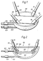
- Figure 1 shows that part of a milking machine which is referred to as the "claw" and is suitable for use in the milking of a cow having an udder with four teats.
- the claw has tubes 110 to 113 which lead to known teat cups (not shown) which are applied to the teats of a cow for milking.
- the tubes 110 to 113 lead via respective transducers 114 to 117 to a hollow housing 118 which is divided into upper and lower chambers 119 and 120 by a partition 121.
- a main pipe 122 leads from the chamber 120, via a transducer 123, to a milk treatment device, for example a cooler, and a milk storage tank.
- a pipe 124 leads from the chamber 119 via a transducer 125 to a dump bucket (not shown) or a drain. Pulse tubes are omitted from the drawing for clarity but may be arranged in known manner.
- the tube 110 divides into branches 126 and 127 which lead respectively into the chambers 119 and 120.
- a valve 128 represented diagrammatically in Figure 2 is provided to direct milk entering the housing 118 along the tube 110 into either the branch 126 or the branch 127.
- An electrically energisable actuator (not shown) is provided for moving the valve 128 to a selected position.
- Each of the tubes 111, 112 and 113 is provided with branches corresponding to the branches 126 and 127 and with a valve corresponding to the valve 128.
- the transducer 114 is adapted for applying energy to the milk and means is provided for monitoring the effect of the milk on the applied energy.
- the transducer 114 may be a known device for applying electromagnetic energy to the milk which flows along the tube 110 and known means for responding to the effect of the milk on the applied energy.
- the operation of the transducer 114 may be based on a known technique for detecting the presence of specific, organic substances.
- the transducer 114 way be other than a transducer for applying energy to the milk.
- the transducer 114 may be an electrical device, a property of which is affected by one or more specific substances which may be present in the milk.
- the device may be an ion sensitive field effect transistor.
- the device may be arranged for carrying out chromatographic analysis of the milk.
- the passage for flow of milk past the transducer may be arranged to exclude air bubbles from a part of the passage in the vicinity of the transducer.
- the transducers 115, 116 and 117 may be identical with the transducer 114.
- the transducers 123 and 125 may differ from the transducers 114 to 117 but each may be one of the kinds of devices mentioned above.
- the transducers 123 and 125 may be adapted for determining the presence of one or more specific substances whilst the transducers 114 to 117 are adapted for detecting the presence of one or more different substances.
- the transducers 123 and 125 may be omitted.
- the transducers 114 to 117, 123 and 125, or some of these transducers, are connected with a processor (not shown) for processing signals provided by the transducers.
- the processor may be incorporated in the housing 118 or may be at a central station remote from the housing. In the latter case, the processor is preferably arranged to process signals received from a number of claws identical to or similar to the claw of Figures 1 and 2.
- the central station may include one or more indicators, for example a device providing a visual indication of an abnormal or seasonal condition, and preferably includes means for recording information derived from the several claws.
- the apparatus of Figures 1 and 2 is used in the milking of a cow.
- the valves are set to divert milk from each teat into the chamber 119, during an initial stage of milking, which may last for only a few seconds, the fore milk is discarded.
- the milk from each teat is monitored by the transducers 114 to 117 for the presence of substances which are produced by mastitis in the udder of the cow. If no such substances are detected, then, after the initial stage of milking, the valves are operated to divert the milk from all of the teats into the chamber 120, from which it flows to the storage tank.
- the monitoring is carried out only during the initial stage of milking and the valves then set, according to the result, for the duration of the milking of the particular animal on that occasion. Whilst it is possible for the apparatus to be set to continue to monitor for the duration of the milking process, this has been found to be unsatisfactory in that milk ceases to flow at different times from different teats. As the flow from one teat diminishes, air entering the milk in the region of the transducer will change the output and may lead to a false indication.
- the transducers 114 to 117 may be transducers which provide an electrical signal which represents the electrical conductivity of the milk.
- the signals from the transducers 114 to 117 can be compared electronically to provide a comparison of the electrical conductivity of the milk from each teat. An output from the electronic comparison can be used to provide automatic control of actuation of the valves 128.
- manually operable or remotely operable means may be provided for controlling actuation of the valves 128 and this may over-ride automatic control. Provision is made for resetting the valves after manual operation.
- the transducers 114 to 117 may be adapted to provide signals representing the concentration of ions, for example potassium ions, sodium ions or hydrogen ions, or to provide a signal indicating the concentration of nagase in the milk.
- transducers 114 to 117 are adapted for providing signals which indicate the presence of or the concentrations of other substances in the milk, for example progesterone and pheromone.
- the presence of these substances in the milk provides an important indication about the condition of the cow and comparison of the concentrations in the milk from different teats may not provide additional useful information.
- a transducer provided at 123 or 125 could be used to obtain this information.
- Figures 3 to 6 illustrate an apparatus embodying the invention in which electrical conductivity of milk is monitored so as to provide an indication of the presence of a substance resulting from mastitis.
- Figure 3 illustrates the known principle upon which the electrical detection apparatus of this example is based.
- Two toroidally wound coils comprise windings on a former which may best be visualised as a rectangular section straight rod on which windings extend from one end to the other, and the rod is then bent so that its ends join and its axis (the continuous axis) forms a circle.
- a medium 11, whose electrical conductivity is to be measured, is arranged to form a conductive loop threading the two coils which provide respectively a drive coil 12 and a detection coil 13.
- the conducting loop 11 of the test medium will provide coupling by transformer action with the detection coil 13.
- the degree of coupling between the drive coil 12 and the detection coil 13 is dependent upon the conductivity of the conducting loop 11. A measure of this conductivity can thus be derived from measurement of the current induced in the detection coil 13.
- Figure 3a represents schematically the equivalent circuit of Figure 3.
- Figure 7 illustrates the electrical detection apparatus incorporated in a milking claw which comprises an enclosure 14 which is generally circular in plan.
- the section shows two of four sensors 21 and two of the inlet pipes 18 leading to known teat cup (not shown) to be applied to the teat of a cow for milking.
- the claw has an upper chamber 15 and a lower chamber 51. Screw threaded into a hole in the base plate in each chamber 15 is a sensor 21 for detecting changes in the electrical conductivity of milk.
- Each sensor 21 is positioned within a cylindrical pot 52.
- Each inlet pipe 18 is positioned so as to be directly over the respective pot 52.
- An outlet pipe 53 leads from the upper chamber 15 to a dump bucket or drain.
- the lower chamber 51 has an outlet pipe 54 leading to the milk treatment device and milk storage tank.
- each transducer in this modification has a central aperture 55 providing an outlet opening at the bottom of the respective pot 52.
- a valve 56 operated by a solenoid 57 is moveable by the solenoid 57 between a closed position and an open position.
- the valve 56 associated with the sensor 21 on the left of the figure is shown in the closed position, whilst the valve on the right hand side of the figure is shown in the open position.
- the solenoids 57 and also the integrated circuit electronics package marked IC is accommodated within a recess in the upper part of the chamber 51.
- the sensor 21 comprises a toroidally wound drive coil 22 and a substantially identically constructed detector coil 23.
- the coils are wound on rectangular section formers 24 and the windings extend around the full circumferential extent of the toroids.
- the coil windings are encapsulated in insulating material and fit within appropriately toroidally shaped hollow copper cans 25, 26 which are electrically connected to earth.
- the drive coil 22 is thus isolated from the detector coil 23.
- Each can has an open end 27, 28 and the cans 25, 26 are assembled back-to-back so that the open ends 27 and 28 are remote from one another.
- the copper cans 25 and 26 are spaced apart from one another and the whole assembly encapsulated in insulating material.
- valves 56 are all initially closed and the first milk to arrive through each of the inlet pipes 18 flows into and fills to overflowing the pots 52 containing the sensors 21. Overflow milk escapes through the outlet pipe 53.
- the encapsulated coils are attached to the mounting boss 32a on legs 33 so that there is space for the milk to form a closed electrically conducting loop which threads both of the toroidally wound coils 22, 23.
- output from the detection coil 23 is connected across a tuning capacitor C1 to an operational amplifier OA1 providing a gain of approximately 100.
- Output from the operational amplifier OA1 is fed on line L1 to detection circuitry described further below, and on line L2 to a circuit which controls the drive to the drive coil 22.
- the signal on line L2 is applied to operational amplifier OA2 set up as a high gain amplifier operating effectively as a switch.
- the output from operational amplifier OA2 is applied across Zener diodes Z1 and Z2 connected back-to-back.
- the drive coil 22 together with its parallel connected tuning capacitor C2 is connected across the back-to-back Zener diodes Z1 and Z2.
- any initial signal detected from the detection coil 23 will be at the resonant frequency of this coil together with capacitor C1. Consequently the signal on line L2 will cause amplifier OA2 to switch at this frequency.
- the Zener diodes Z1 and Z2 are therefore driven alternately to breakdown and the output applied across the drive coil 22 is a square wave of amplitude equal to twice the breakdown voltage of the Zener diodes and frequency equal to the resonant frequency of the detection coil 23.
- This circuit arrangement thus provides that the frequency of the drive is held locked to the resonant frequency of the tuned circuit formed by the detection coil 23 together with the tuning capacitor C1 and will follow changes should there be any as a consequence of changes in the operating conditions of the sensor 21.
- the voltage of the output signal from the detection coil 23 is dependent upon the coupling between the drive coil 22 and detection coil 23 which is in turn dependent upon the conductivity of the milk.
- the output voltage from the detection coil 23 thus provides an indication of conductivity.
- the sensitivity of this indication is at a maximum when the detection coil 23 is operating at resonance
- any slight departure from the resonant frequency will affect significantly the output voltage. It is thus of critical importance that the frequency or the drive is held at the resonance frequency of the detection coil circuit.
- this is not critical since the resonant frequency of the drive coil circuit affects the efficiency with which the drive signal is coupled but will not affect the frequency of the drive signal.
- the signal on line L1 is converted to a direct voltage, indicative of the conductivity of the milk, by a half wave rectifier comprising operational amplifier OA3 and associated diodes D1 and D2, the direct negative feedback via diode D1 effectively cutting off the negative half cycle.
- the rectified signal is smoothed by the combination of resistor R3 and capacitor C3 and the output buffered by operational amplifier OA4.
- Figure 5 shows the continuation of the circuit, with this output on line L3 being combined at a summing point P with a voltage from operational amplifier OA5, the value of which is adjustable by variable resistor VR1 as a zero offset.
- a further operational amplifier OA6 with variable resistor VR2 in the feedback path provides for scale adjustment and final output from sensor 21 at point A1.
- Each sensor in the claw 14 is provided with identical electronic circuitry from detection coil to output A1.
- the corresponding outputs are shown on Figure 5 labelled A2, A3, A4. These are summed and an average generated by operational amplifier OA7 to provide a reference output on line L4.
- a comparator OA8 for each channel, a comparator OA8, as shown in Figure 6, is provided and the reference level on L4 compared with the output, shown for A1 in Figure 6.
- the comparator OA8 is set up so that lamp LP is illuminated when the signal on Line A1 differs by more than a predetermined amount from the level on line L4.
- the apparatus is initially set up with a liquid in each of the chambers 15 having an electrical conductivity less than is likely to be encountered in the test medium (milk).
- variable resistor VR1 is adjusted to give a scale zero readout.
- the liquid in each channel is then replaced with a liquid having a conductivity in excess of the maximum expected.
- the variable resistor VR2 is adjusted to give a maximum scale deflection.
- the reference level on L4 will represent the average conductivity of the milk passing through the four chambers 15. If any one chamber 15 receives milk at a conductivity level differing significantly from the average, then the appropriate lamp LP(5) for that channel will light up.
- the valve 56 for that particular pot is held closed for the duration of that milking session. All the milk from the associated teat is thus directed to the dump bucket or drain via pipe 53. When the flow from inlet pipe 18 from that particular teat ceases, remaining milk in the pot 52 drains slowly out through a small drain hole 58 at the bottom of the pot 52.
- valve 56 is opened after the initial short period of time necessary for the test, and the good milk flows into the lower chamber 51 and out to the cooler and collection tank via pipe 54.
- valve controlling outflow from the pots 52 into the lower chamber 51 may be used.
- the invention is not restricted to the details of the foregoing examples. For instance, it is not essential to use zener diodes 21 and 22 in the drive circuitry shown in Figure 4.
- the amplifier OA2 operating at high gain, is effectively switched at the natural resonance frequency of the detector circuit. However, the operation of amplifier OA2 is more satisfactory if the zener diodes are included.
- An equivalent and effective unitary structure can be provided by a pair of co-axial cylinders with a dividing wall extending across the space between the cylinders perpendicularly to the axis and mid-way between the ends of the cylinders.
- the unitary structure can be made from any material of suitably high electrical conductivity.
Landscapes
- Life Sciences & Earth Sciences (AREA)
- Animal Husbandry (AREA)
- Environmental Sciences (AREA)
- Engineering & Computer Science (AREA)
- Food Science & Technology (AREA)
- Health & Medical Sciences (AREA)
- Chemical & Material Sciences (AREA)
- Medicinal Chemistry (AREA)
- Physics & Mathematics (AREA)
- Analytical Chemistry (AREA)
- Biochemistry (AREA)
- General Health & Medical Sciences (AREA)
- General Physics & Mathematics (AREA)
- Immunology (AREA)
- Pathology (AREA)
- Investigating Or Analyzing Materials By The Use Of Electric Means (AREA)
Claims (12)
- Vorrichtung zur Verwendung beim Melken eines Tieres, welche eine Melkklaue mit einer Anzahl von Zufluß- bzw. Einlaßbahnen (110, 111, 112, 113; 18), eine gemeinsame Auslaßbahn (54, 122), eine zusätzliche Auslaßbahn (53, 124), einen jeweiligen Meßaufnehmer (114, 115, 116, 117; 21), der jeder Zuflußbahn zugeordnet ist, um ein quantitatives Signal bereitzustellen, das die Größe einer Eigenschaft von Milch in dieser Bahn darstellt, und ein Vergleichsmittel (OA8) umfaßt, um das Signal in jeder Zuflußbahn mit einer Referenz zu vergleichen, die während des Melkens aus den Größen der genannten Eigenschaft der Milch in der genannten Anzahl von Zuflußbahnen (110, 111, 112, 113; 18) abgeleitet wird, wobei das Vergleichsmittel (OA8) ein Ausgangssignal bereitstellt, das die Zuflußbahn kennzeichnet, in der die Milch eine Größe der genannten Eigenschaft aufweist, die um mehr als einen vorbestimmten Betrag von der Referenzgröße abweicht, wobei jede der genannten Zuflußbahnen mit einem Abzweigventil (56, 128) versehen ist, das die Strömung aus der Zuflußbahn weg von der gemeinsamen Auslaßbahn (54, 122) zu der zusätzlichen Auslaßbahn (53, 124) abzweigen kann, dadurch gekennzeichnet, daß die Meßaufnehmer (114, 115, 116, 117; 21), die jeweiligen Abzweigventile (56, 128) und die Zufluß- und Auslaßbahnen, die den Abzweigventilen (56, 128) zugeordnet sind, sämtliche innerhalb der Melkklaue enthalten sind.
- Vorrichtung nach Anspruch 1, weiter gekennzeichnet durch Steuermittel, die auf das Ausgangssignal ansprechen und das Ventil (56, 128) in der Zuflußbahn betätigen bzw. steuern, die durch das Ausgangssignal gekennzeichnet ist, um die Strömung in die genannte zusätzliche Auslaßbahn (53, 124) abzuzweigen.
- Vorrichtung nach Anspruch 2, weiter gekennzeichnet dadurch, daß das Vergleichsmittel (OA8) und das Steuermittel ebenfalls innerhalb der Melkklaue untergebracht ist.
- Vorrichtung nach Anspruch 2 oder 3, weiter gekennzeichnet dadurch, daß das Steuermittel so angeordnet ist, daß während einer Anfangsphase des Melkens die Ventile (56, 128) Milch von sämtlichen der Zuflußbahnen zu der zusätzlichen Auslaßbahn (53, 124) leiten und zum Ende der Anfangsphase einige oder sämtliche der Ventile (56, 128) betätigt werden, um Milch von der entsprechenden Zuflußbahn zu der genannten gemeinsamen Auslaßbahn (54, 122) zu leiten.
- Vorrichtung nach einem der Ansprüche 1 bis 4, weiter gekennzeichnet dadurch, daß Referenzmittel (OA7) die genannte Referenzgröße als Mittelwert von den Signalen erzeugen, die die jeweiligen Größen der Eigenschaft der Milch in den Zuflußbahnen darstellen.
- Vorrichtung nach einem Ansprüche 1 bis 5, weiter gekennzeichnet dadurch, daß zumindest einer der Meßaufnehmer (114, 115, 116, 117; 21) ein nichteindringender Meßaufnehmer ist.
- Vorrichtung nach Anspruch 6, weiter gekennzeichnet dadurch, daß der oder jeder Meßaufnehmer (114, 115, 116, 117; 21) eine Anzahl von elektromagnetischen Induktivitäten (22, 23) umfaßt, die so angeordnet sind, daß sie elektromagnetisch mit Milch in der entsprechenden Zuflußbahn (18) gekoppelt sind.
- Vorrichtung nach Anspruch 6, weiter gekennzeichnet dadurch, daß der oder jeder Meßaufnehmer (21) ein Paar von Ringspulen (22, 23) umfaßt, die so angeordnet sind, daß die Milch eine elektrisch leitende Schleife ausbildet, die die Toroiden umläuft, die durch die Ringspulen ausgebildet sind.
- Vorrichtung nach Anspruch 8, weiter gekennzeichnet dadurch, daß die Spulen in geeignet toroidförmig geformten Kupferbehältern (25, 26), aber elektrisch isoliert zu diesen, enthalten sind, die an einem Ende (27, 28) in einer Ebene parallel zu der Ebene, die die kontinuierliche Achse des Toroids umfaßt, offen sind.
- Vorrichtung nach Anspruch 9, weiter gekennzeichnet dadurch, daß die Kupferbehälter (25, 26) jeweils eine Treiberspule (22) und eine Detektionsspule (23) umfassen und angrenzend zueinander aber elektrisch voneinander isoliert auf der selben Hauptachse montiert sind, jedoch mit ihren jeweiligen offenen Enden (27, 28) voneinander abgewandt sind.
- Vorrichtung nach Anspruch 10, dadurch gekennzeichnet, daß eine elektrische Stromversorgung (M1, OA2, Z1, Z2) geschaltet ist, um an die Treiberspule (22) einen Wechselstrom anzulegen, und daß eine Detektionsschaltung (OA1, OA3, OA4) für elektrische Signale geschaltet ist, um die Amplitude des in der Detektionsspule (23) induzierten Wechselstroms zu detektieren.
- Vorrichtung nach Anspruch 11, weiter gekennzeichnet dadurch, daß jede Spule (22, 23) ein Bauelement eines Resonanz- bzw. Schwingkreises ist und daß die genannte Detektionsschaltung (OA1) geschaltet ist, um die Stromversorgung zu steuern, um so die Frequenz des AC-Treiberstroms für die Treiberspule (22) auf der oder nahe bei der Resonanzfrequenz der Schaltung aufrechtzuhalten, die die Detektionsspule (23) umfaßt.
Applications Claiming Priority (1)
| Application Number | Priority Date | Filing Date | Title |
|---|---|---|---|
| PCT/GB1992/001848 WO1994008450A1 (en) | 1992-10-09 | 1992-10-09 | Apparatus for and method of milking an animal |
Publications (2)
| Publication Number | Publication Date |
|---|---|
| EP0616492A1 EP0616492A1 (de) | 1994-09-28 |
| EP0616492B1 true EP0616492B1 (de) | 2000-05-17 |
Family
ID=10709428
Family Applications (1)
| Application Number | Title | Priority Date | Filing Date |
|---|---|---|---|
| EP92921303A Expired - Lifetime EP0616492B1 (de) | 1992-10-09 | 1992-10-09 | Vorrichtung zum melken eines tieres |
Country Status (5)
| Country | Link |
|---|---|
| US (1) | US5664521A (de) |
| EP (1) | EP0616492B1 (de) |
| AU (1) | AU2690792A (de) |
| DE (1) | DE69231064T2 (de) |
| WO (1) | WO1994008450A1 (de) |
Families Citing this family (12)
| Publication number | Priority date | Publication date | Assignee | Title |
|---|---|---|---|---|
| US6161502A (en) * | 1991-04-30 | 2000-12-19 | Tickleford Limited | Apparatus for and method of milking an animal |
| SE9600413L (sv) * | 1996-02-05 | 1997-06-09 | Alfa Laval Agri Ab | Spenkoppscental |
| DE19630146C2 (de) * | 1996-07-25 | 1998-06-10 | Jakob Maier | Vorrichtung zur automatischen Milchaussonderung |
| US6378455B1 (en) * | 1997-10-13 | 2002-04-30 | N.V. Nederlandsche Apparatenfabrik Nedap | Intelligent claw |
| SE9704781D0 (sv) * | 1997-12-19 | 1997-12-19 | Alfa Laval Agri Ab | A method and an apparatus for separation of foremilk |
| DK1126757T3 (da) * | 1998-11-05 | 2002-12-30 | Chemometec As | System til regulering af mælkehåndtering under malkeprocessen samt fremgangsmåde til regulering af malkeprocessen |
| NL1014780C2 (nl) * | 2000-03-29 | 2001-02-20 | Idento Electronics Bv | Werkwijze en inrichting voor het melken van vee. |
| ATE271766T1 (de) * | 2000-03-31 | 2004-08-15 | Delaval Holding Ab | Automatische melkvorrichtung |
| NZ523369A (en) | 2002-12-20 | 2005-08-26 | Dec Int Nz Ltd | Milk processing |
| SE0401513D0 (sv) * | 2004-06-14 | 2004-06-14 | Delaval Holding Ab | Rotary parlour with delivery lines |
| US8076143B2 (en) * | 2005-05-25 | 2011-12-13 | Westfall Geofrey J | Method for determining quality of milk and presence of mastitis |
| CN102576008A (zh) * | 2009-06-09 | 2012-07-11 | 塔图大学 | 用于检测乳腺炎和奶质量的方法以及乳腺炎传感器 |
Citations (1)
| Publication number | Priority date | Publication date | Assignee | Title |
|---|---|---|---|---|
| EP0385539A2 (de) * | 1989-02-27 | 1990-09-05 | C. van der Lely N.V. | Melkanlage |
Family Cites Families (15)
| Publication number | Priority date | Publication date | Assignee | Title |
|---|---|---|---|---|
| DE293429C (de) * | ||||
| GB1314327A (en) * | 1969-06-30 | 1973-04-18 | Nat Res Dev | Methods and apparatus for the detection of mastitis in milk animals |
| GB1314326A (en) * | 1969-06-30 | 1973-04-18 | Nat Res Dev | Methods and apparatus for the detection of mastitis in milk animals |
| FR2061906A5 (de) * | 1969-10-01 | 1971-06-25 | Nat Res Dev | |
| SU389759A1 (ru) * | 1972-02-25 | 1973-07-11 | Б. Д. Шевченко, Т. А. Лупу , Д. И. Болбочан Кишиневский сельскохоз йственный институт М. В. Фрунзе | Коллектор доильного аппарата |
| GB1494831A (en) * | 1974-08-02 | 1977-12-14 | Fraser D | Methods and means for detection of micro-biological organisms and other contaminants in fluids |
| CA1003900A (en) * | 1975-01-16 | 1977-01-18 | Sed Systems Ltd. | Fluid conductivity measurement apparatus |
| US4190020A (en) * | 1978-01-03 | 1980-02-26 | Mezogazdasagi Foiskola, Kaposvar | Process and equipment for machine milking to provide sterile milk free from blood and pus |
| US4344385A (en) * | 1978-05-03 | 1982-08-17 | Babson Bros. Co. | Milker |
| JPS5513842A (en) * | 1978-07-14 | 1980-01-31 | Eisai Co Ltd | Check unit for milking of udders |
| JPS5935574B2 (ja) * | 1980-12-24 | 1984-08-29 | エーザイ株式会社 | 分房乳の検査装置を具えたミルククロ− |
| DE3650506D1 (de) * | 1985-11-01 | 1996-05-09 | Nz Ministry Agriculture & Fisheries | Melkmaschinen |
| GB2182534B (en) * | 1985-11-12 | 1989-10-04 | Ambic Equip Ltd | Improvements in or relating to automatic milking apparatus and methods |
| DE3935759A1 (de) * | 1989-10-27 | 1991-05-02 | Lang Apparatebau Gmbh | Vorrichtung und verfahren zur messung der elektrischen leitfaehigkeit von milch |
| GB2257008B (en) * | 1991-04-30 | 1994-11-09 | Sidney William Simpson | Sub clinical mastitis detector and excluder |
-
1992
- 1992-10-09 AU AU26907/92A patent/AU2690792A/en not_active Abandoned
- 1992-10-09 WO PCT/GB1992/001848 patent/WO1994008450A1/en not_active Ceased
- 1992-10-09 US US08/244,708 patent/US5664521A/en not_active Expired - Lifetime
- 1992-10-09 DE DE69231064T patent/DE69231064T2/de not_active Expired - Fee Related
- 1992-10-09 EP EP92921303A patent/EP0616492B1/de not_active Expired - Lifetime
Patent Citations (1)
| Publication number | Priority date | Publication date | Assignee | Title |
|---|---|---|---|---|
| EP0385539A2 (de) * | 1989-02-27 | 1990-09-05 | C. van der Lely N.V. | Melkanlage |
Also Published As
| Publication number | Publication date |
|---|---|
| AU2690792A (en) | 1994-05-09 |
| DE69231064T2 (de) | 2000-09-28 |
| WO1994008450A1 (en) | 1994-04-28 |
| DE69231064D1 (de) | 2000-06-21 |
| EP0616492A1 (de) | 1994-09-28 |
| US5664521A (en) | 1997-09-09 |
Similar Documents
| Publication | Publication Date | Title |
|---|---|---|
| EP0616492B1 (de) | Vorrichtung zum melken eines tieres | |
| US6161502A (en) | Apparatus for and method of milking an animal | |
| EP0733884B1 (de) | Mengenmesser und damit ausgerüstete Vorrichtung zum Melken von Tieren | |
| EP1022937B1 (de) | Intelligente melkklaue | |
| US5094112A (en) | Process and a device for carrying out measurements at a foaming liquid | |
| EP0018419B1 (de) | Vorrichtung zur kontrolle von milch | |
| US3695230A (en) | Apparatus for the detection of mastitis in milk animals | |
| US4010715A (en) | Fluid conductivity detecting means | |
| US2898549A (en) | Means and techniques for determining quality of milk | |
| US6571731B1 (en) | Apparatus for automatic selecting out of milk | |
| CA2229354C (en) | Somatic cell analyser | |
| EP1443324A1 (de) | Milchmengenmessvorrichtung und Verfahren zum Melken eines Tieres | |
| EP1155610B1 (de) | Mengenmesser und damit ausgerüstete Vorrichtung zum Melken von Tieren | |
| US6307362B1 (en) | Somatic cell analyser | |
| US4299495A (en) | Density meter | |
| US6479017B2 (en) | Device for measuring an electrical parameter in the milk | |
| NZ244815A (en) | Animal milking: electrical property of milk from each teat continually measured and diverted if mastitis indicating property detected | |
| US4306517A (en) | Device for reporting the end of a milking period | |
| SU1720600A1 (ru) | Микропроцессорный счетчик молока | |
| EP0666475B1 (de) | Konstruktion zum Melken von Tieren | |
| FI74540B (fi) | System och anordning foer maetning av en vaetskas hoejdnivao. | |
| GB2271426A (en) | Electrical detection apparatus using resonant circuits | |
| RU2327343C1 (ru) | Устройство для учета надоев молока | |
| WO2004042329A1 (en) | Liquid flow measuring apparatus | |
| SU1509005A1 (ru) | Электронное устройство дл диагностики мастита у коров |
Legal Events
| Date | Code | Title | Description |
|---|---|---|---|
| PUAI | Public reference made under article 153(3) epc to a published international application that has entered the european phase |
Free format text: ORIGINAL CODE: 0009012 |
|
| 17P | Request for examination filed |
Effective date: 19940607 |
|
| AK | Designated contracting states |
Kind code of ref document: A1 Designated state(s): DE FR IE NL |
|
| RAP1 | Party data changed (applicant data changed or rights of an application transferred) |
Owner name: TICKLEFORD LIMITED |
|
| 17Q | First examination report despatched |
Effective date: 19951227 |
|
| GRAG | Despatch of communication of intention to grant |
Free format text: ORIGINAL CODE: EPIDOS AGRA |
|
| RTI1 | Title (correction) |
Free format text: APPARATUS FOR MILKING AN ANIMAL |
|
| GRAG | Despatch of communication of intention to grant |
Free format text: ORIGINAL CODE: EPIDOS AGRA |
|
| GRAH | Despatch of communication of intention to grant a patent |
Free format text: ORIGINAL CODE: EPIDOS IGRA |
|
| GRAH | Despatch of communication of intention to grant a patent |
Free format text: ORIGINAL CODE: EPIDOS IGRA |
|
| GRAA | (expected) grant |
Free format text: ORIGINAL CODE: 0009210 |
|
| AK | Designated contracting states |
Kind code of ref document: B1 Designated state(s): DE FR IE NL |
|
| REG | Reference to a national code |
Ref country code: IE Ref legal event code: FG4D |
|
| ET | Fr: translation filed | ||
| REF | Corresponds to: |
Ref document number: 69231064 Country of ref document: DE Date of ref document: 20000621 |
|
| PLBE | No opposition filed within time limit |
Free format text: ORIGINAL CODE: 0009261 |
|
| STAA | Information on the status of an ep patent application or granted ep patent |
Free format text: STATUS: NO OPPOSITION FILED WITHIN TIME LIMIT |
|
| 26N | No opposition filed | ||
| PGFP | Annual fee paid to national office [announced via postgrant information from national office to epo] |
Ref country code: NL Payment date: 20050123 Year of fee payment: 13 |
|
| PGFP | Annual fee paid to national office [announced via postgrant information from national office to epo] |
Ref country code: IE Payment date: 20050211 Year of fee payment: 13 |
|
| PGFP | Annual fee paid to national office [announced via postgrant information from national office to epo] |
Ref country code: FR Payment date: 20050224 Year of fee payment: 13 |
|
| PG25 | Lapsed in a contracting state [announced via postgrant information from national office to epo] |
Ref country code: IE Free format text: LAPSE BECAUSE OF NON-PAYMENT OF DUE FEES Effective date: 20051010 |
|
| PG25 | Lapsed in a contracting state [announced via postgrant information from national office to epo] |
Ref country code: NL Free format text: LAPSE BECAUSE OF NON-PAYMENT OF DUE FEES Effective date: 20060501 |
|
| PGFP | Annual fee paid to national office [announced via postgrant information from national office to epo] |
Ref country code: DE Payment date: 20060502 Year of fee payment: 14 |
|
| PG25 | Lapsed in a contracting state [announced via postgrant information from national office to epo] |
Ref country code: FR Free format text: LAPSE BECAUSE OF NON-PAYMENT OF DUE FEES Effective date: 20060630 |
|
| NLV4 | Nl: lapsed or anulled due to non-payment of the annual fee |
Effective date: 20060501 |
|
| REG | Reference to a national code |
Ref country code: IE Ref legal event code: MM4A |
|
| REG | Reference to a national code |
Ref country code: FR Ref legal event code: ST Effective date: 20060630 |
|
| PG25 | Lapsed in a contracting state [announced via postgrant information from national office to epo] |
Ref country code: DE Free format text: LAPSE BECAUSE OF NON-PAYMENT OF DUE FEES Effective date: 20070501 |