EP0616757A2 - Dispositif de labourage - Google Patents
Dispositif de labourage Download PDFInfo
- Publication number
- EP0616757A2 EP0616757A2 EP94200275A EP94200275A EP0616757A2 EP 0616757 A2 EP0616757 A2 EP 0616757A2 EP 94200275 A EP94200275 A EP 94200275A EP 94200275 A EP94200275 A EP 94200275A EP 0616757 A2 EP0616757 A2 EP 0616757A2
- Authority
- EP
- European Patent Office
- Prior art keywords
- soil
- roller
- cultivating machine
- soil cultivating
- seed
- Prior art date
- Legal status (The legal status is an assumption and is not a legal conclusion. Google has not performed a legal analysis and makes no representation as to the accuracy of the status listed.)
- Withdrawn
Links
Images

Classifications
-
- A—HUMAN NECESSITIES
- A01—AGRICULTURE; FORESTRY; ANIMAL HUSBANDRY; HUNTING; TRAPPING; FISHING
- A01C—PLANTING; SOWING; FERTILISING
- A01C5/00—Making or covering furrows or holes for sowing, planting or manuring
- A01C5/06—Machines for making or covering drills or furrows for sowing or planting
- A01C5/066—Devices for covering drills or furrows
- A01C5/068—Furrow packing devices, e.g. press wheels
-
- A—HUMAN NECESSITIES
- A01—AGRICULTURE; FORESTRY; ANIMAL HUSBANDRY; HUNTING; TRAPPING; FISHING
- A01B—SOIL WORKING IN AGRICULTURE OR FORESTRY; PARTS, DETAILS, OR ACCESSORIES OF AGRICULTURAL MACHINES OR IMPLEMENTS, IN GENERAL
- A01B29/00—Rollers
- A01B29/06—Rollers with special additional arrangements
-
- A—HUMAN NECESSITIES
- A01—AGRICULTURE; FORESTRY; ANIMAL HUSBANDRY; HUNTING; TRAPPING; FISHING
- A01B—SOIL WORKING IN AGRICULTURE OR FORESTRY; PARTS, DETAILS, OR ACCESSORIES OF AGRICULTURAL MACHINES OR IMPLEMENTS, IN GENERAL
- A01B49/00—Combined machines
- A01B49/04—Combinations of soil-working tools with non-soil-working tools, e.g. planting tools
- A01B49/06—Combinations of soil-working tools with non-soil-working tools, e.g. planting tools for sowing or fertilising
- A01B49/065—Combinations of soil-working tools with non-soil-working tools, e.g. planting tools for sowing or fertilising the soil-working tools being actively driven
Definitions
- the present invention relates to a soil cultivating machine for the purpose of combined working and sowing of soil, comprising soil working elements and a following packer roller constituted by a plurality of roller elements arranged in side-by-side relationship for creating furrows in which the sowing can take place by locally compressing the worked soil, the machine further comprising a seed drill with seed delivery tubes, mounted on or at least supported by the packer roller during operation, a seed delivery tube being arranged behind each roller element for depositing seeds on the precompressed soil in a respective furrow.
- a suchlike machine has the advantage that compaction, which facilitates capillary supply of moisture and support for emerging plants, does not occur between the rows. In this area weeds might otherwise emerge as favourably as the crop seeds deposited within the rows. Also, in such a machine, the crop seeds do not undergo the sometimes less favourable pressure exerted by the roller elements, as compared to alternative constructions wherein the crop seeds are deposited to the front of a roller. Alternatively, however, the machine has for disadvantage that the contact between deposited seed and the compacted soil, necessary for absorbing the supplied moisture, is less favourable as when the seed were deposited to the front of a roller element.
- the present invention has for its object a construction overcoming the above-described disadvantages. According to the invention, this can be achieved when the machine comprises further pressure rollers, each operating at least predominantly in the line of a respective furrow and being arranged behind a seed delivery tube, and pivotably around a horizontal axis in the machine, by means of an arm carrying said further pressure roller. In this way it is made possible to exert only a relatively low pressure, enough for bringing the crop seeds in good contact with the compressed soil, however, due to the pivotable connection of the further pressure rollers in the machine, without the weight of the seed drill and the packer roller or any other machine part.
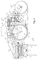
- the implement shown in the drawings comprises a soil cultivating machine 1, in particular one for preparing a seed bed.
- the machine includes a box-like frame portion 2 which extends transversely to the direction of operative travel A. Inside the frame portion 2 there are bearing-supported at equal interspaces of preferably 25 cms, the upwardly extending, preferably vertical, shafts 3 of soil working members 4. At the end of the shaft 3 projecting from the bottom side of the frame portion 2, each of the soil working members 4 includes a carrier 5, said carrier having near its ends downwardly extending soil working elements 6 in the form of tines.
- the ends of the box-like frame portion 2 are provided with upwardly extending plates 7 which are located at least substantially parallel to the direction of operative travel A.
- supports 8 which extend in the direction of operative travel A and, seen in plan view, extend to beyond the leading side thereof.
- a beam 9 which extends parallel to the frame portion 2, to which beam 9 there are fitted by means of bushings 11 and clamping bolts 12 five downwardly extending, at least substantially vertical, carriers 10.
- the lower ends of the carriers 10 are provided with goosefoot-like soil working members 13 for working the subsoil. As is apparent from Figure 1, the soil working members 13 are distributed along the entire length of the beam 9.
- the clamping bolts 12 the carriers 10 can be adjusted to a plurality of positions for setting the working depth of the goosefoot-like soil working members 13.
- a gear wheel 14 is mounted on each shaft 3 of a soil working member 4, the arrangement being such that the gear wheels 14 on the shafts of adjacent soil working members 4 are in driving connection with each other.
- the shaft 3 of a soil working member 4 is extended upwardly and reaches to into a gear box 15 arranged on the upper side of the frame portion 2.
- the extension is in driving connection with a shaft which extends in the direction of operative travel A and which via a speed variator 16 located at the rear side of the gear box is in driving connection with a superjacent shaft 17, which shaft 17 projects from the gear box 15 at the leading side and can be coupled to the power take-off shaft of a tractor via an intermediate shaft.
- a trestle 18 which encloses the gear box and at its leading side is provided with coupling means for coupling the machine to the three-point lifting hitch of a tractor.
- each of the plates 7 is fitted with a shaft 19 which extends transversely to the direction of operative travel A, the arrangement being such that the longitudinal centre lines of the shafts 19 are in alignment.
- an arm 20 which extends rearwardly along a plate 7, which arm 20, seen in plan view, is folded downwardly in a position just behind the box-like frame portion 2 through a portion 21.
- the portion 21 merges into a portion 22 which extends obliquely upwardly and rearwardly and in its turn merges into a rearwardly extending, at least substantially horizontal portion 23.
- a seed drill 25 is bolted to the horizontal portion 23 of the arms 20 by means of bolts 24.
- the seed drill 25 includes upwardly directed plates 26 which extend into the direction of operative travel A and by means of the bolts 24 are connected detachably to the portion 23 of the arms 20.
- the plates 26 are interconnected at the rear side by means of a cross-beam 27.
- the beam 27, which is located near the portion 23 of the arms 20, is provided at its lower side with U-shaped portions 28, the legs of which extend downwardly.
- the U-shaped portions 28 are located at a short distance from each other and are secured by means of bolts 29.
- an arm 31 which extends obliquely downwardly and forwardly from a portion 28.
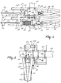
- each arm 31 supports a roller element 33 by means of an at least substantially horizontal shaft 32 extending transversely to the direction of operative travel.
- Each roller element 33 consists of two portions 34 which are each other's mirror image and are interconnected near the centre thereof, thereby forming an outwardly extending edge 35.
- the shaft 32 is furthermore supported by an arm 35A which extends obliquely upwardly and rearwardly from the shaft 32 and is connected to the arm 31 by means of a supporting strip 36 ( Figure 3).
- the upper end of the arm 35A is connected pivotably via a shaft 37 to a block 38 which is slidable along a rod 39.
- the one end of the rod 39 is arranged pivotably by means of a block 40, a shaft 41 and an adapter bushing 42 between the upwardly directed legs of U-shaped portions 43 which are bolted to the upper side of the beam 27 by means of the bolts 29.
- a pressure spring 44 is provided around the rod 39 between the blocks 38 and 40.
- the other end of the rod 39 is a threaded one having screwed thereon two nuts 45, the arrangement being such that the nuts constitute a stop for the slidable block 38 attached to the arm 35A.
- the adjacent roller elements 33 which are movable in height independently of each other, together constitute a roller, by means of which the soil cultivating machine is also supported during operation.
- the frame portion 2 can bear on the portion 22 of the arms 20 via pins 46, so that it can deflect upwardly when meeting an obstacle.
- the pins 46 can be inserted into one of a plurality of apertures 47 provided in supports 48 connected to the rear side of the plates 7. By means of the pins 46, it is possible to adjust the working depth of the soil working members 4.
- an arm 31 is provided with an obliquely downwardly and forwardly extending carrier 48A which at its lower end is fitted with a scraper 49 having near its centre a slot to receive the edge 35 of a roller element 33, while the leading sides of the scraper portions located on either sides of the edge 35 extend to the circumference thereof ( Figure 3).
- the seed drill 25 includes a hopper 50 accommodating a discharge mechanism which may be designed and be driven in a known per se manner. At their leading sides there are arranged between the plates 26, near the upper and lower ends thereof, cross beams 51 which are provided with attachment means 52 and 53, by means of which the seed drill, if employed as the only implement, can be coupled to the three-point lifting hitch of a tractor.
- each seed delivery tube 54 is adjustable in height relative to a bracket-shaped support 57 which is arranged pivotably between the legs of a U-shaped portion 28 by means of a shaft 58.
- Each support 57 supports an arm 59 which extends obliquely downwardly and rearwardly.
- the lower end of each arm 59 is provided on both sides with a shaft 60 for two adjacent pressure rollers 61 which, taken in the direction of operative travel A, are arranged relative to each other in the shape of a V.
- the soil working members 4 can be driven from the power take-off shaft via the intermediate shaft and the above-described transmission - adjacent soil working members rotating in opposite directions - and they work at least contiguous strips of soil by means of their tine-like soil working elements 5, after the soil has been loosened effectively by the goosefoot-like soil working members 13 at a depth which substantially corresponds to the working depth of the soil working elements 4.
- the above-described implement is eminently suitable for sowing grains, the spring-loaded support of the assembly by means of the spring-loaded roller elements 33 ensuring an accurate sowing.
- the frame portion 2 of the soil cultivating machine 1 can move in height relative to the arms 20, as a result of which a floating support of the machine is obtained.
- the above-described seed drill 25 can be detached from the arms 20 after the bolts 24 have been loosened, and be attached for individual use to the three-point lifting hitch of a tractor by means of the coupling means 52, 53.
- a constant sowing depth can be maintained, because the roller elements 33 located before each of the seed coulters 55 can adapt themselves in an excellent manner to prevailing soil unevennesses, so that even in possible wheel tracks the sowing can be effected at the same depth as in the intermediate strip of soil.
Landscapes
- Life Sciences & Earth Sciences (AREA)
- Soil Sciences (AREA)
- Environmental Sciences (AREA)
- Engineering & Computer Science (AREA)
- Mechanical Engineering (AREA)
- Soil Working Implements (AREA)
- Agricultural Machines (AREA)
Applications Claiming Priority (3)
| Application Number | Priority Date | Filing Date | Title |
|---|---|---|---|
| NL8903162 | 1989-12-27 | ||
| NL8903162A NL8903162A (nl) | 1989-12-27 | 1989-12-27 | Grondbewerkingsmachine. |
| EP90203244A EP0436975B1 (fr) | 1989-12-27 | 1990-12-11 | Machine pour le travail du sol |
Related Parent Applications (1)
| Application Number | Title | Priority Date | Filing Date |
|---|---|---|---|
| EP90203244.0 Division | 1990-12-11 |
Publications (2)
| Publication Number | Publication Date |
|---|---|
| EP0616757A2 true EP0616757A2 (fr) | 1994-09-28 |
| EP0616757A3 EP0616757A3 (fr) | 1996-03-06 |
Family
ID=19855834
Family Applications (2)
| Application Number | Title | Priority Date | Filing Date |
|---|---|---|---|
| EP94200275A Withdrawn EP0616757A3 (fr) | 1989-12-27 | 1990-12-11 | Dispositif de labourage. |
| EP90203244A Expired - Lifetime EP0436975B1 (fr) | 1989-12-27 | 1990-12-11 | Machine pour le travail du sol |
Family Applications After (1)
| Application Number | Title | Priority Date | Filing Date |
|---|---|---|---|
| EP90203244A Expired - Lifetime EP0436975B1 (fr) | 1989-12-27 | 1990-12-11 | Machine pour le travail du sol |
Country Status (4)
| Country | Link |
|---|---|
| EP (2) | EP0616757A3 (fr) |
| DE (1) | DE69012976T2 (fr) |
| FR (1) | FR2656194A1 (fr) |
| NL (1) | NL8903162A (fr) |
Cited By (1)
| Publication number | Priority date | Publication date | Assignee | Title |
|---|---|---|---|---|
| RU2494595C2 (ru) * | 2011-11-03 | 2013-10-10 | Государственное бюджетное образовательное учреждение высшего профессионального образования Нижегородский государственный инженерно-экономический институт (НГИЭИ) | Способ посева пропашных культур |
Families Citing this family (7)
| Publication number | Priority date | Publication date | Assignee | Title |
|---|---|---|---|---|
| FR2717103B1 (fr) * | 1994-03-11 | 1996-07-26 | Lely France | Dispositif pour l'épandage et le malaxage de produits. |
| GB2323511B (en) * | 1997-06-26 | 1999-05-19 | Simba International Limited | A press ring for an agricultural machine |
| DE102010017631A1 (de) * | 2010-06-29 | 2011-12-29 | Amazonen-Werke H. Dreyer Gmbh & Co. Kg | Landwirtschaftliche Bestellkombination |
| CN105659956B (zh) * | 2016-03-31 | 2017-08-15 | 山东胜伟园林科技有限公司 | 适用于盐碱地使用的免耕播种机 |
| CN107493741B (zh) * | 2017-08-21 | 2021-04-02 | 宜宾锦尚花生态农业开发有限公司 | 树苗种植专用小型土壤压实装置 |
| CN112166719B (zh) * | 2020-09-08 | 2022-07-05 | 安徽科技学院 | 一种用于农业土壤的改良设备 |
| CN112544146B (zh) * | 2020-12-02 | 2021-12-21 | 农业农村部南京农业机械化研究所 | 适于稻茬田黏重土壤的小麦条播机用整地机构 |
Family Cites Families (9)
| Publication number | Priority date | Publication date | Assignee | Title |
|---|---|---|---|---|
| DE8350C (de) * | 1879-06-08 | 1879-12-05 | C. STAROSTE, Gutsbesitzer, in Tschauchelwitz bei Breslau | Drillwalze für Rübenkultur |
| US2152212A (en) * | 1938-08-08 | 1939-03-28 | Bernard C Reinkens | Ditcher and packer machine |
| NL6909787A (fr) * | 1969-06-26 | 1970-12-29 | ||
| DE2528930A1 (de) * | 1975-06-28 | 1977-01-13 | Amazonen Werke Dreyer H | Tragrahmen fuer landwirtschaftliche maschinen und geraete |
| DE3336216C2 (de) * | 1983-10-05 | 1986-09-25 | H. Niemeyer Söhne GmbH & Co KG, 4446 Hörstel | Einzelkornsämaschine |
| DE8706550U1 (de) * | 1986-05-13 | 1987-07-23 | Amazonen-Werke H. Dreyer Gmbh & Co Kg, 4507 Hasbergen | Bodenwalze |
| ATE142841T1 (de) * | 1986-11-04 | 1996-10-15 | Lely Nv C Van Der | Bodenbearbeitungsmaschine zur saatbettherrichtung |
| DE3640399C1 (en) * | 1986-11-26 | 1988-03-17 | Joachim Brunotte | Single-row or multi-row crust breaker for the comminution of encrusted soil layers above seedlings in sugar-beet cultivation |
| DE8913171U1 (de) * | 1989-11-07 | 1990-01-18 | Rabewerk Heinrich Clausing, 4515 Bad Essen | Bodenbearbeitungsgerät |
-
1989
- 1989-12-27 NL NL8903162A patent/NL8903162A/nl not_active Application Discontinuation
-
1990
- 1990-12-11 EP EP94200275A patent/EP0616757A3/fr not_active Withdrawn
- 1990-12-11 EP EP90203244A patent/EP0436975B1/fr not_active Expired - Lifetime
- 1990-12-11 DE DE1990612976 patent/DE69012976T2/de not_active Expired - Lifetime
- 1990-12-12 FR FR9015557A patent/FR2656194A1/fr active Granted
Cited By (1)
| Publication number | Priority date | Publication date | Assignee | Title |
|---|---|---|---|---|
| RU2494595C2 (ru) * | 2011-11-03 | 2013-10-10 | Государственное бюджетное образовательное учреждение высшего профессионального образования Нижегородский государственный инженерно-экономический институт (НГИЭИ) | Способ посева пропашных культур |
Also Published As
| Publication number | Publication date |
|---|---|
| NL8903162A (nl) | 1991-07-16 |
| DE69012976T2 (de) | 1995-05-11 |
| DE69012976D1 (de) | 1994-11-03 |
| EP0436975A1 (fr) | 1991-07-17 |
| EP0616757A3 (fr) | 1996-03-06 |
| FR2656194B1 (fr) | 1995-01-20 |
| FR2656194A1 (fr) | 1991-06-28 |
| EP0436975B1 (fr) | 1994-09-28 |
Similar Documents
| Publication | Publication Date | Title |
|---|---|---|
| US4241674A (en) | Sub-soil planter | |
| US4108089A (en) | Agricultural implements | |
| US4506609A (en) | Trash seeder | |
| AU2008281337B2 (en) | Profiling method and apparatus | |
| US4034687A (en) | Cultivators | |
| US4036154A (en) | Soil cultivating implements | |
| CZ115498A3 (cs) | Integrované zařízení pro kultivaci půdy | |
| US5318134A (en) | Irrigation furrow and raised seed bed forming machine | |
| EP0513939B1 (fr) | Machine pour le travail du sol | |
| EP0198563B1 (fr) | Machine agricole | |
| EP0199406B1 (fr) | Charrue | |
| US4432292A (en) | Floating planter | |
| US4058068A (en) | Soil cultivating and sowing implement | |
| EP0436975A1 (fr) | Machine pour le travail du sol | |
| EP0335456B2 (fr) | Engin à moteur de culture de la terre | |
| EP0422721A1 (fr) | Dispositif agricole, particulièrement machine de travail du sol | |
| EP0620962B1 (fr) | Machine de travail du sol | |
| EP0305601B1 (fr) | Appareil pour cultiver le sol | |
| EP0201135B1 (fr) | Machine pour le travail du sol | |
| GB2176982A (en) | Rotary cultivator | |
| EP0432815A2 (fr) | Machine agricole | |
| EP0200273A1 (fr) | Machine pour le travail du sol | |
| RU48142U1 (ru) | Почвообрабатывающее орудие | |
| HU206007B (en) | Agricultural machine group | |
| JPS6041047Y2 (ja) | ロ−タリ機に備える播種床形成装置 |
Legal Events
| Date | Code | Title | Description |
|---|---|---|---|
| PUAI | Public reference made under article 153(3) epc to a published international application that has entered the european phase |
Free format text: ORIGINAL CODE: 0009012 |
|
| AC | Divisional application: reference to earlier application |
Ref document number: 436975 Country of ref document: EP |
|
| AK | Designated contracting states |
Kind code of ref document: A2 Designated state(s): DE FR GB NL |
|
| PUAL | Search report despatched |
Free format text: ORIGINAL CODE: 0009013 |
|
| AK | Designated contracting states |
Kind code of ref document: A3 Designated state(s): DE FR GB NL |
|
| STAA | Information on the status of an ep patent application or granted ep patent |
Free format text: STATUS: THE APPLICATION IS DEEMED TO BE WITHDRAWN |
|
| 18D | Application deemed to be withdrawn |
Effective date: 19960907 |