EP0616775A2 - Transporteur à chaînes pour appareils à ouvrir des oeufs - Google Patents
Transporteur à chaînes pour appareils à ouvrir des oeufs Download PDFInfo
- Publication number
- EP0616775A2 EP0616775A2 EP94301913A EP94301913A EP0616775A2 EP 0616775 A2 EP0616775 A2 EP 0616775A2 EP 94301913 A EP94301913 A EP 94301913A EP 94301913 A EP94301913 A EP 94301913A EP 0616775 A2 EP0616775 A2 EP 0616775A2
- Authority
- EP
- European Patent Office
- Prior art keywords
- chain
- track apparatus
- tensioning mechanism
- pair
- chains
- Prior art date
- Legal status (The legal status is an assumption and is not a legal conclusion. Google has not performed a legal analysis and makes no representation as to the accuracy of the status listed.)
- Granted
Links
Images


Classifications
-
- B—PERFORMING OPERATIONS; TRANSPORTING
- B65—CONVEYING; PACKING; STORING; HANDLING THIN OR FILAMENTARY MATERIAL
- B65G—TRANSPORT OR STORAGE DEVICES, e.g. CONVEYORS FOR LOADING OR TIPPING, SHOP CONVEYOR SYSTEMS OR PNEUMATIC TUBE CONVEYORS
- B65G23/00—Driving gear for endless conveyors; Belt- or chain-tensioning arrangements
- B65G23/44—Belt or chain tensioning arrangements
-
- A—HUMAN NECESSITIES
- A47—FURNITURE; DOMESTIC ARTICLES OR APPLIANCES; COFFEE MILLS; SPICE MILLS; SUCTION CLEANERS IN GENERAL
- A47J—KITCHEN EQUIPMENT; COFFEE MILLS; SPICE MILLS; APPARATUS FOR MAKING BEVERAGES
- A47J43/00—Implements for preparing or holding food, not provided for in other groups of this subclass
- A47J43/14—Devices or machines for opening raw eggs or separating the contents thereof
- A47J43/145—Machines therefor
Definitions
- This invention relates to a track apparatus for egg breaking mechanisms which can be advantageously incorporated in an automatic egg breaking apparatus for successively breaking eggs and taking out their contents.
- eggs have found wide use.
- the egg yolk may be used as a material for making mayonnaise or other food products.
- the egg white (albumen) may be used for making pharmaceutical products or as a binder for protein products. Due to such wide use of the egg, it is absolutely necessary in industry to use an automatic egg breaking apparatus for breaking eggs and taking out their contents at high speed.
- Japanese Patent Publication No. 61-59089 discloses an egg breaking apparatus wherein an endless chain conveyor as a track apparatus carries a plurality of egg breaking mechanisms at a constant pitch along the endless moving path of the chain conveyor.
- the chain conveyor is held in engagement with a plurality of sprocket assemblies as direction change assemblies, so that the moving path of the chain conveyor is divided by the direction change assemblies into different regions where each of the egg breaking mechanisms is caused to perform different operations which include egg reception, egg breaking, cleaning, and etc.
- One of the sprocket assemblies is a drive sprocket assembly for causing movement of the chain conveyor.
- a track apparatus for egg breaking mechanisms comprising: an endless chain conveyor extending along an endless moving path and carrying the egg breaking mechanisms; a drive sprocket assembly held in driving engagement with the chain conveyor and serving as a direction change assembly for changing an extending direction of the moving path; and at least two additional direction change assemblies contacting the chain conveyor for further changing the extending direction of the moving path; characterized in that the additional direction change assemblies comprise a chain tensioning mechanism for slidably guiding the chain conveyor.
- the chain tensioning mechanism need not have any toothed portion which would require a troublesome cleaning operation.
- the track apparatus as a whole can be cleaned more easily or conveniently than the prior art track apparatus.
- the track apparatus may further comprise an adjusting mechanism for positionally adjusting the chain tensioning mechanism to thereby adjust a tension applied to the chain conveyor.
- the additional direction change assemblies may comprise an idle sprocket assembly held in engagement with the chain conveyor.
- the chain conveyor comprises a pair of vertically spaced chains
- the drive sprocket assembly comprises a pair of vertically spaced drive sprockets in engagement with the respective chains.
- the pair of chains may be preferably guided by a corresponding pair of vertically spaced chain guide rails each of which is in the form of a downwardly open channel member.
- Each of the egg breaking mechanisms may have an upper end portion provided with a roller for coming into rolling contact with an upper one of the chain guide rails from above. Such an arrangement is preferred for insuring smooth movement of the chain conveyor.
- the chain tensioning mechanism may comprise a pair of vertically spaced chain guide plates each of which has an arcuate sliding surface for slidably guiding a corresponding one of the chains. Further, an arcuate roller guide may be arranged along and above the arcuate sliding surface of an upper one of the chain guide plates, so that the roller of the egg breaking mechanism can also come into rolling contact with the roller guide from above.
- the chain tensioning mechanism may be movably supported on a machine base.
- the adjusting mechanism may comprise a carrier fixed to the underside of the chain tensioning mechanism and having an internally threaded bore, and an externally threaded shaft rotatably mounted on the machine base in engagement with the threaded bore.
- the threaded shaft may be made rotatable by a handle.
- the machine base may have a slot in which the carrier is slidably guided.
- the moving path of the chain conveyor is made generally triangular.
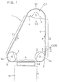
- the egg breaking apparatus 1 comprises a pair of drive sprockets 2 as a first direction change point, a pair of idle sprockets 3 as a second direction change point, and a chain tensioning mechanism CT as a third direction change point.
- the respective drive sprockets 2 are vertically spaced from each other as supported on a common drive shaft 2a.
- the drive shaft 2a is connected to a drive motor (not shown) through a suitable reduction mechanism (not shown).
- the drive sprockets themselves are known, so that the details relating to them are not described here.
- the respective idle sprockets 3 are vertically spaced from each other as supported on a common idle shaft 3a.
- the drive sprockets themselves are known, so that their details are not described here.
- the chain tensioning mechanism CT includes a pair of chain guide plates 4 which are vertically spaced from each other. The details of the chain guide plates 4 will be described hereinafter.
- a pair of endless chains 5 (see also Fig. 2), namely, a chain conveyor, connect the pair of drive sprockets 2, the pair of idle sprockets 3 and the chain tensioning mechanism CT.
- the chains 5 move an endless moving path, as indicated by arrows P.
- the pair of drive sprockets 2, the pair of idle sprockets 3 and the chain tensioning mechanism CT are disposed at the respective apexes of a right-angled triangle.
- the chain moving path is divided into three different regions which include an egg receiving region A, an egg breaking region B and an aftertreatment region C, as more specifically described later.
- the egg breaking apparatus 1 has a machine base 6 from which a plurality of upright support arms 7 (only one shown) extend as suitably spaced from each other along the moving path (Fig. 1) of the chains 5 except for the portion of the chain tensioning mechanism CT.
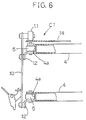
- Each of the support arms 7 fixedly carries a rail mount 8 which, in turn, fixedly carries a pair of vertically spaced mounting lugs 8a for attachment to respective guide rails 9 by welding for example.
- Each of the guide rails 9 is a channel member which is downwardly open for receiving a corresponding one of the chains 5.
- Each of the chains 5 is fixedly connected to a plurality of holders 10 by means of angle plates 12 as suitably spaced along the chain moving path (see also Fig. 1).
- Each of the holders 10 has an upper end provided with a roller 11 which rolls on the upper one of the guide rails 9.
- each of the holders 10 removably carries an egg breaking mechanism 20 which mainly comprises an egg presser 21, an egg support 22, and a knife assembly 23. Since the egg breaking mechanism is not the subject of the present invention, the details of the egg breaking mechanism are not described here.
- each of the holders 10 further carries a cup assembly 24 which includes an upper cup 24a and a lower cup 24b.
- the upper cup 24a receives the content of a broken egg from a corresponding egg breaking mechanism 20 above but has a slot (not shown) which allows falling of the egg white portion (albumen) while retaining only the egg yolk portion.
- the lower cup 24b receives the egg white portion falling from the upper cup 24a.
- each of the chain guide plates 4 of the chain tensioning mechanism CT is connected together by a plurality of connecting bars 13.
- Each of the chain guide plates 4 has an arcuate sliding surface 4a for guiding contact with a corresponding one of the chains 5 (Fig. 6).
- the upper one of the chain guide plates 4 carries an arcuate roller guide 14 extending along the arcuate sliding surface 4a for supporting the roller 11 (Fig. 6) of each holder 10.
- the roller guide 14 is arranged substantially flush and continuous with the upper surface of the upper one of the chain guide rails 9 (Figs. 4 and 5).
- the chain tensioning mechanism CT is positionally adjustable on the machine base 6 (see Fig. 5) by means of an adjusting mechanism 15.
- This adjusting mechanism includes a slot 16 formed in a top wall portion of the machine base 6, a carrier 17 extending downward from the underside of the chain tensioning mechanism CT for slidably penetrating through the slot 16, and an externally threaded shaft 18 engaging in an internally threaded bore 17a of the carrier 17 and supported on the machine base 6 for rotation by a handle 19.
- the position of the chain tensioning mechanism CT is adjustable back and forth by turning the handle 19, as indicated by arrows Q1, Q2 in Figs. 4 and 5.
- an egg conveyor 31 (see Fig. 1) successively supplies rows of eggs (not shown) to an egg shifting device 32.
- Each row of eggs may include six eggs for example, so that the egg shifting device 32 simultaneously shifts six eggs to a group of six egg breaking mechanisms 20 (see Fig. 3) in the egg receiving region A of the chain moving path between the pair of drive sprockets 2 and the pair of idle sprockets 3.
- the egg conveyor 31 and the egg shifting device 32 may be of the known type, so that their details are not described herein.
- Each egg breaking mechanism 20 breaks the received egg as it moves from the pair of drive sprockets 2 to the chain tensioning mechanism CT in the egg breaking region B of the chain moving path.
- the operation of the egg breaking mechanism 20 may be controlled by cams (not shown) arranged along the moving path of the chains 5 for example.
- aftertreatments which include distinguishing between acceptable egg contents and objectionable egg contents (at an inspection unit), separately collecting the yoke and white portions of the acceptable egg contents via different chutes (not shown) while discharging the objectionable egg contents, cleaning each egg breaking mechanism 20 at a cleaning unit (not shown), and so on.
- the inspection unit, the chutes and the cleaning unit together with a controller (not shown) may be arranged along the chain moving path.
- one of the direction change points of the chain moving path is provided by the chain tensioning mechanism CT which slidably guides the chains 5. Due to the absence of sprocket teeth, the chain tensioning mechanism CT can be conveniently cleaned to prevent or reduce bacterial growth or breeding.
- the chain tensioning mechanism CT may be positionally adjusted for suitably adjusting the tension applied to the chains 5.
- the triangular configuration of the chain moving path is preferred for saving an installation space.
- the pair of idle sprockets 3 may be replaced by another chain tensioning mechanism which is similar to the one already described herein.
- the endless chain moving path may rendered rectangular or trapezoidal by adding another chain tensioning mechanism.
Landscapes
- Engineering & Computer Science (AREA)
- Mechanical Engineering (AREA)
- Food Science & Technology (AREA)
- Meat, Egg Or Seafood Products (AREA)
- Food-Manufacturing Devices (AREA)
- Drives For Endless Conveyors (AREA)
- Chain Conveyers (AREA)
Applications Claiming Priority (2)
| Application Number | Priority Date | Filing Date | Title |
|---|---|---|---|
| JP5091989A JP2995523B2 (ja) | 1993-03-26 | 1993-03-26 | 割卵機の駆動装置 |
| JP91989/93 | 1993-03-26 |
Publications (3)
| Publication Number | Publication Date |
|---|---|
| EP0616775A2 true EP0616775A2 (fr) | 1994-09-28 |
| EP0616775A3 EP0616775A3 (fr) | 1995-02-08 |
| EP0616775B1 EP0616775B1 (fr) | 1998-05-13 |
Family
ID=14041873
Family Applications (1)
| Application Number | Title | Priority Date | Filing Date |
|---|---|---|---|
| EP94301913A Expired - Lifetime EP0616775B1 (fr) | 1993-03-26 | 1994-03-17 | Transporteur à chaínes pour appareils à ouvrir des oeufs |
Country Status (5)
| Country | Link |
|---|---|
| US (1) | US5410953A (fr) |
| EP (1) | EP0616775B1 (fr) |
| JP (1) | JP2995523B2 (fr) |
| DE (1) | DE69410150D1 (fr) |
| ES (1) | ES2115157T3 (fr) |
Cited By (1)
| Publication number | Priority date | Publication date | Assignee | Title |
|---|---|---|---|---|
| US9895027B2 (en) | 2014-01-24 | 2018-02-20 | Gullfoss Engineering, LLC | Egg-breaking systems and methods |
Families Citing this family (7)
| Publication number | Priority date | Publication date | Assignee | Title |
|---|---|---|---|---|
| US5617782A (en) * | 1995-03-31 | 1997-04-08 | Diamond Automations, Inc. | Method and apparatus for breaking, separating, and inspecting eggs |
| IT1282422B1 (it) * | 1995-06-09 | 1998-03-23 | Euroegg Ind S R L | Macchina per lo sgusciamento automatico di uova fresche |
| US5628246A (en) * | 1996-03-01 | 1997-05-13 | Sanovo Engineering A/S | Egg processing machine |
| JP4662100B2 (ja) * | 2001-04-04 | 2011-03-30 | 東洋自動機株式会社 | 袋詰め包装機における袋移送装置 |
| JP4695199B2 (ja) * | 2006-02-23 | 2011-06-08 | サノボ・エンジニアリング・アクティーゼルスカブ | 割卵装置に卵を給送する方法及び割卵装置 |
| CN104187842B (zh) * | 2014-08-26 | 2016-09-28 | 上海伟隆机械设备股份有限公司 | 生蛋自动去壳装置 |
| CN110217575A (zh) * | 2019-07-10 | 2019-09-10 | 辽宁东升精机有限公司 | 换热器芯体组装机多层扁管链式发料机构 |
Family Cites Families (10)
| Publication number | Priority date | Publication date | Assignee | Title |
|---|---|---|---|---|
| US3480056A (en) * | 1967-03-21 | 1969-11-25 | Charles H Willsey | Egg breaking machine |
| US3854394A (en) * | 1973-01-04 | 1974-12-17 | Seymour Foods Inc | Egg liquid extractor apparatus |
| US3926304A (en) * | 1974-11-04 | 1975-12-16 | Mitsubishi Heavy Ind Ltd | Stretch adjusting device for a conveyor in a conveyor-line working system |
| DE2511420A1 (de) * | 1975-03-15 | 1976-09-23 | Siemag Transplan Gmbh | Spannvorrichtung fuer kettenfoerderer |
| US4137838A (en) * | 1976-12-29 | 1979-02-06 | Warren William H | Means for breaking and separating eggs |
| US4321864A (en) * | 1980-01-22 | 1982-03-30 | Willsey Charles H | Egg breaking and contents separating machine |
| US4605562A (en) * | 1982-05-11 | 1986-08-12 | Kewpie Kabushiki Kaisha | High speed egg breaking method |
| JPS6159089A (ja) * | 1984-08-31 | 1986-03-26 | 横浜ゴム株式会社 | ホ−ス |
| US4764387A (en) * | 1987-01-30 | 1988-08-16 | Seymour Foods, Inc. | Albumen collection method |
| US4773322A (en) * | 1987-01-30 | 1988-09-27 | Seymour Foods, Inc. | Albumen recovery apparatus |
-
1993
- 1993-03-26 JP JP5091989A patent/JP2995523B2/ja not_active Expired - Lifetime
-
1994
- 1994-03-10 US US08/208,274 patent/US5410953A/en not_active Expired - Fee Related
- 1994-03-17 DE DE69410150T patent/DE69410150D1/de not_active Expired - Lifetime
- 1994-03-17 EP EP94301913A patent/EP0616775B1/fr not_active Expired - Lifetime
- 1994-03-17 ES ES94301913T patent/ES2115157T3/es not_active Expired - Lifetime
Cited By (1)
| Publication number | Priority date | Publication date | Assignee | Title |
|---|---|---|---|---|
| US9895027B2 (en) | 2014-01-24 | 2018-02-20 | Gullfoss Engineering, LLC | Egg-breaking systems and methods |
Also Published As
| Publication number | Publication date |
|---|---|
| JPH06276952A (ja) | 1994-10-04 |
| EP0616775B1 (fr) | 1998-05-13 |
| EP0616775A3 (fr) | 1995-02-08 |
| US5410953A (en) | 1995-05-02 |
| DE69410150D1 (de) | 1998-06-18 |
| ES2115157T3 (es) | 1998-06-16 |
| JP2995523B2 (ja) | 1999-12-27 |
Similar Documents
| Publication | Publication Date | Title |
|---|---|---|
| EP0616775B1 (fr) | Transporteur à chaínes pour appareils à ouvrir des oeufs | |
| US6055694A (en) | Wafer scrubbing machine | |
| US5988351A (en) | Conveyor with rotating and offloading of conveyed units | |
| US5699595A (en) | Apparatus for needling a fibrous web | |
| EP0847941B1 (fr) | Dispositif pour le transfert d'articles séparés, tels que des oeufs et des fruits, d'un convoyeur d'alimentation à un dispositif d'emballage | |
| KR20010041431A (ko) | 농산물 선별 이송 메커니즘 | |
| KR890701268A (ko) | 와이어 송출장치 | |
| EP2225942B1 (fr) | Dispositif pour étendre une pâte alimentaire | |
| GB2174666A (en) | Sorting device with conveyor sections | |
| US5029691A (en) | Chain conveyor and pallet | |
| JP4543485B2 (ja) | 無端チェーンコンベア清掃装置 | |
| JPH10109740A (ja) | 振分コンベア | |
| JPS6251850B2 (fr) | ||
| AU752121B2 (en) | Dough packing machine with tiltable spoons | |
| KR19980070119A (ko) | 과일선별장치 | |
| KR970058818A (ko) | 스크루우 선별장치 | |
| JP2721923B2 (ja) | 選別装置の供給装置 | |
| JPS5918196B2 (ja) | シヨクヒンサイダンキノ フラツピングボウシヨウロ−ラ−キコウ | |
| RU1784180C (ru) | Машина дл резки овощей продолговатой формы | |
| CA2997678C (fr) | Machine de formation de sandwich entrainee par courroie | |
| SU221861A1 (ru) | Привод для подачи изделий | |
| AU753699B2 (en) | Detachable spoon for a dough packing machine | |
| KR940004561Y1 (ko) | 벽돌 방향 전환기의 벽돌 인입장치 | |
| CS238539B1 (cs) | Podávači mechanismus | |
| NL9300212A (nl) | Inrichting voor het aanvoeren en in één rij verder transporteren van cilindrische voorwerpen. |
Legal Events
| Date | Code | Title | Description |
|---|---|---|---|
| PUAI | Public reference made under article 153(3) epc to a published international application that has entered the european phase |
Free format text: ORIGINAL CODE: 0009012 |
|
| AK | Designated contracting states |
Kind code of ref document: A2 Designated state(s): DE DK ES FR IT NL |
|
| PUAL | Search report despatched |
Free format text: ORIGINAL CODE: 0009013 |
|
| AK | Designated contracting states |
Kind code of ref document: A3 Designated state(s): DE DK ES FR IT NL |
|
| 17P | Request for examination filed |
Effective date: 19950223 |
|
| 17Q | First examination report despatched |
Effective date: 19970115 |
|
| GRAG | Despatch of communication of intention to grant |
Free format text: ORIGINAL CODE: EPIDOS AGRA |
|
| GRAG | Despatch of communication of intention to grant |
Free format text: ORIGINAL CODE: EPIDOS AGRA |
|
| GRAG | Despatch of communication of intention to grant |
Free format text: ORIGINAL CODE: EPIDOS AGRA |
|
| GRAH | Despatch of communication of intention to grant a patent |
Free format text: ORIGINAL CODE: EPIDOS IGRA |
|
| ITF | It: translation for a ep patent filed | ||
| GRAH | Despatch of communication of intention to grant a patent |
Free format text: ORIGINAL CODE: EPIDOS IGRA |
|
| GRAA | (expected) grant |
Free format text: ORIGINAL CODE: 0009210 |
|
| AK | Designated contracting states |
Kind code of ref document: B1 Designated state(s): DE DK ES FR IT NL |
|
| PG25 | Lapsed in a contracting state [announced via postgrant information from national office to epo] |
Ref country code: FR Free format text: LAPSE BECAUSE OF FAILURE TO SUBMIT A TRANSLATION OF THE DESCRIPTION OR TO PAY THE FEE WITHIN THE PRESCRIBED TIME-LIMIT Effective date: 19980513 |
|
| REG | Reference to a national code |
Ref country code: ES Ref legal event code: FG2A Ref document number: 2115157 Country of ref document: ES Kind code of ref document: T3 |
|
| REF | Corresponds to: |
Ref document number: 69410150 Country of ref document: DE Date of ref document: 19980618 |
|
| PG25 | Lapsed in a contracting state [announced via postgrant information from national office to epo] |
Ref country code: DK Free format text: LAPSE BECAUSE OF FAILURE TO SUBMIT A TRANSLATION OF THE DESCRIPTION OR TO PAY THE FEE WITHIN THE PRESCRIBED TIME-LIMIT Effective date: 19980813 |
|
| PG25 | Lapsed in a contracting state [announced via postgrant information from national office to epo] |
Ref country code: DE Free format text: LAPSE BECAUSE OF FAILURE TO SUBMIT A TRANSLATION OF THE DESCRIPTION OR TO PAY THE FEE WITHIN THE PRESCRIBED TIME-LIMIT Effective date: 19980814 |
|
| EN | Fr: translation not filed | ||
| PLBE | No opposition filed within time limit |
Free format text: ORIGINAL CODE: 0009261 |
|
| STAA | Information on the status of an ep patent application or granted ep patent |
Free format text: STATUS: NO OPPOSITION FILED WITHIN TIME LIMIT |
|
| 26N | No opposition filed | ||
| PGFP | Annual fee paid to national office [announced via postgrant information from national office to epo] |
Ref country code: NL Payment date: 20020228 Year of fee payment: 9 |
|
| PGFP | Annual fee paid to national office [announced via postgrant information from national office to epo] |
Ref country code: ES Payment date: 20020320 Year of fee payment: 9 |
|
| PG25 | Lapsed in a contracting state [announced via postgrant information from national office to epo] |
Ref country code: ES Free format text: LAPSE BECAUSE OF NON-PAYMENT OF DUE FEES Effective date: 20030318 |
|
| PG25 | Lapsed in a contracting state [announced via postgrant information from national office to epo] |
Ref country code: NL Free format text: LAPSE BECAUSE OF NON-PAYMENT OF DUE FEES Effective date: 20031001 |
|
| NLV4 | Nl: lapsed or anulled due to non-payment of the annual fee |
Effective date: 20031001 |
|
| REG | Reference to a national code |
Ref country code: ES Ref legal event code: FD2A Effective date: 20030318 |
|
| PG25 | Lapsed in a contracting state [announced via postgrant information from national office to epo] |
Ref country code: IT Free format text: LAPSE BECAUSE OF NON-PAYMENT OF DUE FEES Effective date: 20050317 |