EP0617120A2 - Fermentationseinrichtung - Google Patents
Fermentationseinrichtung Download PDFInfo
- Publication number
- EP0617120A2 EP0617120A2 EP94810109A EP94810109A EP0617120A2 EP 0617120 A2 EP0617120 A2 EP 0617120A2 EP 94810109 A EP94810109 A EP 94810109A EP 94810109 A EP94810109 A EP 94810109A EP 0617120 A2 EP0617120 A2 EP 0617120A2
- Authority
- EP
- European Patent Office
- Prior art keywords
- fermentation
- container
- fermentation device
- degradation
- stirring
- Prior art date
- Legal status (The legal status is an assumption and is not a legal conclusion. Google has not performed a legal analysis and makes no representation as to the accuracy of the status listed.)
- Granted
Links
Images


Classifications
-
- C—CHEMISTRY; METALLURGY
- C12—BIOCHEMISTRY; BEER; SPIRITS; WINE; VINEGAR; MICROBIOLOGY; ENZYMOLOGY; MUTATION OR GENETIC ENGINEERING
- C12M—APPARATUS FOR ENZYMOLOGY OR MICROBIOLOGY; APPARATUS FOR CULTURING MICROORGANISMS FOR PRODUCING BIOMASS, FOR GROWING CELLS OR FOR OBTAINING FERMENTATION OR METABOLIC PRODUCTS, i.e. BIOREACTORS OR FERMENTERS
- C12M21/00—Bioreactors or fermenters specially adapted for specific uses
- C12M21/04—Bioreactors or fermenters specially adapted for specific uses for producing gas, e.g. biogas
-
- B—PERFORMING OPERATIONS; TRANSPORTING
- B01—PHYSICAL OR CHEMICAL PROCESSES OR APPARATUS IN GENERAL
- B01F—MIXING, e.g. DISSOLVING, EMULSIFYING OR DISPERSING
- B01F31/00—Mixers with shaking, oscillating, or vibrating mechanisms
- B01F31/44—Mixers with shaking, oscillating, or vibrating mechanisms with stirrers performing an oscillatory, vibratory or shaking movement
- B01F31/445—Mixers with shaking, oscillating, or vibrating mechanisms with stirrers performing an oscillatory, vibratory or shaking movement performing an oscillatory movement about an axis
-
- C—CHEMISTRY; METALLURGY
- C12—BIOCHEMISTRY; BEER; SPIRITS; WINE; VINEGAR; MICROBIOLOGY; ENZYMOLOGY; MUTATION OR GENETIC ENGINEERING
- C12M—APPARATUS FOR ENZYMOLOGY OR MICROBIOLOGY; APPARATUS FOR CULTURING MICROORGANISMS FOR PRODUCING BIOMASS, FOR GROWING CELLS OR FOR OBTAINING FERMENTATION OR METABOLIC PRODUCTS, i.e. BIOREACTORS OR FERMENTERS
- C12M27/00—Means for mixing, agitating or circulating fluids in the vessel
- C12M27/02—Stirrer or mobile mixing elements
- C12M27/06—Stirrer or mobile mixing elements with horizontal or inclined stirrer shaft or axis
-
- C—CHEMISTRY; METALLURGY
- C12—BIOCHEMISTRY; BEER; SPIRITS; WINE; VINEGAR; MICROBIOLOGY; ENZYMOLOGY; MUTATION OR GENETIC ENGINEERING
- C12M—APPARATUS FOR ENZYMOLOGY OR MICROBIOLOGY; APPARATUS FOR CULTURING MICROORGANISMS FOR PRODUCING BIOMASS, FOR GROWING CELLS OR FOR OBTAINING FERMENTATION OR METABOLIC PRODUCTS, i.e. BIOREACTORS OR FERMENTERS
- C12M41/00—Means for regulation, monitoring, measurement or control, e.g. flow regulation
- C12M41/12—Means for regulation, monitoring, measurement or control, e.g. flow regulation of temperature
- C12M41/18—Heat exchange systems, e.g. heat jackets or outer envelopes
-
- Y—GENERAL TAGGING OF NEW TECHNOLOGICAL DEVELOPMENTS; GENERAL TAGGING OF CROSS-SECTIONAL TECHNOLOGIES SPANNING OVER SEVERAL SECTIONS OF THE IPC; TECHNICAL SUBJECTS COVERED BY FORMER USPC CROSS-REFERENCE ART COLLECTIONS [XRACs] AND DIGESTS
- Y02—TECHNOLOGIES OR APPLICATIONS FOR MITIGATION OR ADAPTATION AGAINST CLIMATE CHANGE
- Y02E—REDUCTION OF GREENHOUSE GAS [GHG] EMISSIONS, RELATED TO ENERGY GENERATION, TRANSMISSION OR DISTRIBUTION
- Y02E50/00—Technologies for the production of fuel of non-fossil origin
- Y02E50/30—Fuel from waste, e.g. synthetic alcohol or diesel
-
- Y—GENERAL TAGGING OF NEW TECHNOLOGICAL DEVELOPMENTS; GENERAL TAGGING OF CROSS-SECTIONAL TECHNOLOGIES SPANNING OVER SEVERAL SECTIONS OF THE IPC; TECHNICAL SUBJECTS COVERED BY FORMER USPC CROSS-REFERENCE ART COLLECTIONS [XRACs] AND DIGESTS
- Y02—TECHNOLOGIES OR APPLICATIONS FOR MITIGATION OR ADAPTATION AGAINST CLIMATE CHANGE
- Y02W—CLIMATE CHANGE MITIGATION TECHNOLOGIES RELATED TO WASTEWATER TREATMENT OR WASTE MANAGEMENT
- Y02W30/00—Technologies for solid waste management
- Y02W30/40—Bio-organic fraction processing; Production of fertilisers from the organic fraction of waste or refuse
Definitions
- the invention relates to a fermentation device for the biodegradation of organic matter and for the extraction of the biogas produced during the dismantling with a closed container with an introduction opening for fresh material and circulating or inoculating material and discharge openings for the decomposition products and with a stirring device for mixing the fermentation material.
- fermentation is used for the purpose of this description in a general sense and includes aerobic and anaerobic, as well as controlled and uncontrolled biotransformation processes, such as fermentation etc.
- fermentation material denotes the matter in the fermentation process.
- fresh material denotes the organic matter to be broken down
- inoculum stands for organic matter that is taken from the fermentation process and contains the microorganisms and enzymes necessary for the fermentation, and which is added to the fresh goods in discontinuous processes in order to initiate the fermentation.
- Fermentation devices of the type mentioned at the outset are known, including under the name fermentation gas plants.
- the substances supplied to a fermenter as fresh material with partial admixture of inoculum are pre-or in Fermenter heated to process temperature and mixed by a stirring system during the process.
- the resulting gases can, for example, be fed to an energy supply system or used to cover your own process energy.
- the known fermentation gas plants have the disadvantage that the rotating agitators are technically, i.e. Above all, they are mechanical, very complex and consume a lot of energy and that homogeneous mixing and an optimal temperature distribution in the fermentation material is not guaranteed.
- the object of the invention is to remedy these disadvantages by providing a fermentation device which is mechanically simpler and therefore less expensive to produce and operate, and which also ensures optimum mixing and heat distribution.
- the stirring device has stirring blades which are moved in a circle.
- the agitator blades can either be connected to a drive mechanism moving them simultaneously in the container or individually, i.e. be driven independently.
- the agitator blades preferably consist of blades which are fastened to the shafts with supports and cross struts and are arranged transversely to the vertical central plane of the container.
- a flow system for a heating medium is provided on the side walls, which can be divided into several heating circuits in order to vary the temperature in different sectors of the heating surface.
- the flow system is preferably attached to the outside of the container walls.
- scraps are attached to the bottom of the container, with which suspended matter deposited on the bottom of the container is conveyed in batches to a discharge device.
- These scrapes can either be coupled with the drive of the agitator blades or also have separate drives for flexible adjustment of the delivery rate.
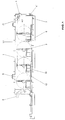
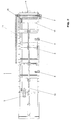
- the fermentation device shown in FIGS. 1 and 2 consists of a rectangular closed container 1 with an inner space 1.1 delimited by flat walls for receiving the fermentation material 4.1.
- the container has an introduction opening 2 for fresh material and circulating or inoculating material and discharge openings 4 and 7 for the degradation products.
- the container also has sampling ports 8 arranged in the side walls, and gas sampling ports 9 arranged in its ceiling.
- a stirring device 3 for mixing the fermentation material and a scraper floor device 12 for the discharge of deposited heavy sediments, such as sand, stones, metal parts etc.
- the mixing is effected by a system of impellers, which are shown in detail in FIGS. 3 and 4.
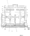
- bearings 13 are located in pairs at approximately half the height of the inner sides of the side walls of the container 1.
- a shaft 14 is mounted in a pair of bearings 13. Overall, four shafts 14 arranged in this way between the side walls are provided, evenly distributed over the length of the container 1.
- a drive gear 15 is attached, which in the present case comprises a sector of about 180 degrees.
- the gear wheel engages in a correspondingly toothed, linearly driven toothed rail 16.
- the toothed rail 16 is connected via a support 17 to a push rod 10 which extends over the entire length of the container 1 and is moved back and forth by a drive device arranged outside the container.
- a drive device arranged outside the container.
- other types of drives e.g. individual hydraulic drives for each shaft etc. are used.
- stirring blades 18 are attached in each case in the middle between the drive gear and the bearings.
- These consist of a carrier 19 fastened to the shaft 14 perpendicularly to the shaft 14, at each end of which there is a cross strut 20 and a blade 21 fastened to this and parallel to the shaft.
- Carrier 19 and strut 20 in the present embodiment consist of H-profiles
- the blade 21 consists of sheet metal.
- the connection between the shaft and carriers, as well as between the shaft and the gear sector, is preferably reinforced with sheet metal angles 22.
- the mixing function is best seen in Fig. 4 b.
- the drive gear sector 15 and thus the shaft 14 and the impeller 18 according to the arrow 24 are rotated counterclockwise.
- the shovel located at the top is pulled downward through the fermentation material and material in the upper layers is brought down.
- the scoop which is initially located at the bottom, and material through it, is pulled from the bottom to the top.
- the discharge of deposited heavy sediments 11 is brought about by scraping 12, which can best be seen in FIG. 5.
- the pawls 12 are connected to the push rod 10 and slide on the bottom of the container 1. They have a wedge-shaped cross section with a ramp-shaped rear side and a steep front. During the return movement (to the left in FIG. 5), the deposited sediments reach the front of the scraper across the ramp area. With the next forward movement, the steep front is then conveyed in the direction of the discharge screw 7.
- the pawls 12 may be in the form of flaps that rise as the stirrer moves linearly backward (to the left in FIG. 5) and thus slide over the deposited material, while sliding as the stirrer moves forward (in FIG. 5) right) and lower the deposits 11 in the vicinity of the discharge screw 7.
- the pawls 12 can preferably be operated independently of the drive of the agitator blades.
- a flow system for a heating medium with a flow line 5 and a return line 6 is arranged along the side walls in the lower region.
- the heat transfer system transfers heat directly to the fermentation material.
- the fermentation material is heated to the required process temperature and radiation losses through the container jacket are compensated.
- the flow system for the heating medium can be divided into several heating circuits, which can be acted on with different heating powers in order to vary the temperature in different sectors of the heating surface. In this way, there is greater flexibility in the control of the temperature profile for optimal adaptation to the requirements of the process.
- the heating medium lines are arranged on the outside of the tank walls. This has the advantage that the inner walls are smooth and less material is deposited.
- the heating elements are preferably designed in the form of double-walled flow systems.
- the fermentation material is mixed by the movement of the impeller 18 and divided by the shear forces that occur. Because the stirring device extends largely over the entire interior 1.1 filled with the fermentation material, there is optimal mixing of the entire fermentation material, which, together with the improved heating mentioned, leads to high process stability and effective degassing of the fermentation material.
- a rectangular or polygonal cross-section of the container with flat walls is optimal for the effectiveness of the stirring device 3.
- a horizontal conveyor spiral 24 is arranged transversely to the longitudinal axis of the system in this area. This conveyor spiral has two halves wound in opposite directions in such a way that material is conveyed from the two lateral areas towards the center with a uniform direction of rotation.
- Another pipe conveyor spiral 25 extends in the longitudinal direction through the system and serves to convey material from the end region back to the start region of the system. This backmixing of already fermented material to the fresh material serves to influence physical and biotechnological process parameters.
- the backmixing spiral can be arranged either in the bottom or in the upper region of the fermentation material, laterally or in the middle.
- FIG. 6 shows the advantageous arrangement of the present fermentation device F in combination with an upstream composting device V and a downstream composting device N.
- Suitable composting devices are, for example, the subject of Swiss patent application No. 03106 / 92-8 and European patent application No. 93810694.5.
Landscapes
- Chemical & Material Sciences (AREA)
- Health & Medical Sciences (AREA)
- Life Sciences & Earth Sciences (AREA)
- Engineering & Computer Science (AREA)
- Bioinformatics & Cheminformatics (AREA)
- Organic Chemistry (AREA)
- Zoology (AREA)
- Wood Science & Technology (AREA)
- Genetics & Genomics (AREA)
- General Engineering & Computer Science (AREA)
- Biomedical Technology (AREA)
- Biotechnology (AREA)
- Microbiology (AREA)
- Sustainable Development (AREA)
- General Health & Medical Sciences (AREA)
- Biochemistry (AREA)
- Molecular Biology (AREA)
- Oil, Petroleum & Natural Gas (AREA)
- General Chemical & Material Sciences (AREA)
- Chemical Kinetics & Catalysis (AREA)
- Physics & Mathematics (AREA)
- Thermal Sciences (AREA)
- Analytical Chemistry (AREA)
- Processing Of Solid Wastes (AREA)
- Fertilizers (AREA)
- Preparation Of Compounds By Using Micro-Organisms (AREA)
- Treatment Of Sludge (AREA)
- Micro-Organisms Or Cultivation Processes Thereof (AREA)
- Apparatus Associated With Microorganisms And Enzymes (AREA)
Abstract
Description
- Die Erfindung betrifft eine Fermentationseinrichtung zum biologischen Abbau von organischer Materie und zur Gewinnung des beim Abbau entstehenden Biogases mit einem geschlossenen Behälter mit einer Einbringöffnung für Frischgut und Umwälz- oder Impfgut und Austragsöffnungen für die Abbauprodukte und mit einer Rühreinrichtung zum Durchmischen des Fermentationsgutes.
- Der Begriff Fermentation wird für den Zweck dieser Beschreibung in einem allgemeinen Sinne verwendet und umfasst aerobe und anaerobe, sowie gesteuerte und nicht gesteuerte Biotransformationsprozesse, wie Gärung etc.
- Mit dem Begriff Fermentationsgut wird in der vorliegenden Beschreibung die im Fermentationsprozess befindliche Materie bezeichnet.
- Mit dem Begriff Frischgut wird die abzubauende organische Materie bezeichnet, der Begriff Impfgut steht für organische Materie, die dem Fermentationsprozess entnommen wird und die für die Fermentation notwendigen Mikroorganismen und Enzyme enthält, und die bei diskontinuierlichen Prozessen dem Frischgut zugefügt wird, um die Fermentation einzuleiten.
- Fermentationseinrichtungen der eingangs genannten Art sind bekannt, unter anderem unter der Bezeichnung Gärgasanlagen. Bei derartigen Anlagen werden die als Frischgut unter teilweiser Beimischung von Impfgut einem Fermenter zugeführten Stoffe vorgängig oder im Fermenter auf Prozesstemperatur erwärmt und während des Prozesses von einem Rührsystem durchmischt. Die entstehenden Gase können beispielsweise einer Energieversorgungsanlage zugeführt oder auch zur Deckung der eigenen Prozessenergie verwendet werden.
- Die bekannten Gärgasanlagen haben den Nachteil, dass die umlaufenden Rührwerke technisch, d.h. vor allem mechanisch, sehr aufwendig sind und viel Energie konsumieren und dass trotzdem homogene Durchmischung und eine für den Prozess optimale Temperaturverteilung im Fermentationsgut nicht gewährleistet ist.
- Der Erfindung liegt die Aufgabe zugrunde, diese Nachteile zu beheben, indem eine mechanisch einfachere und damit kostengünstiger herzustellende und zu betreibende Fermentationseinrichtung bereitgestellt wird, die zudem optimale Durchmischung und Wärmeverteilung gewährleistet.
- Erfindungsgemäss wird diese Aufgabe dadurch gelöst, dass die Rühreinrichtung kreisförmig bewegte Rührflügel aufweist. Die Rührflügel können entweder mit einem sie simultan im Behälter bewegenden Antriebsmechanismus verbunden oder individuell, d.h. unabhängig voneinander angetrieben sein.
- Die Rührflügel bestehen vorzugsweise aus mit Trägern und Querstreben an Wellen befestigten Schaufeln, die quer zur senkrechten Mittelebene des Behälters angeordnet sind.
- Gemäss einer bevorzugten Ausführungsform der Erfindung ist an den Seitenwänden ein Durchlaufsystem für ein Heizmedium vorgesehen, das in mehrere Heizkreise aufgeteilt sein kann, um die Temperatur an verschiedenen Sektoren der Heizfläche zu variieren. Vorzugsweise ist das Durchlaufsystem aussen an den Behälterwänden angebracht.
- Gemäss einer weiteren bevorzugten Ausführungsform der Erfindung sind am Behälterboden Scharren angebracht , mit denen auf dem Behälterboden abgelagerte Sinkstoffe schubweise zu einer Austragsvorrichtung befördert werden. Diese Scharren können entweder mit dem Antrieb der Rührflügel gekoppelt sein oder zwecks flexibler Anpassung der Förderleistung ebenfalls getrennte Antriebe besitzen.
- Im Folgenden werden anhand der beiliegenden Zeichnungen bevorzugte Ausführungsbeispiele der Erfindung beschrieben. Es zeigen
- Fig. 1
- eine Fermentationseinrichtung in Seitenansicht mit abgeschnittener Behälterseitenwand
- Fig. 2
- eine Fermentationseinrichtung in Draufsicht mit abgeschnittener Behälterdecke
- Fig. 3
- eine Fermentationseinrichtung in Frontansicht mit abgeschnittener Behälterfrontwand
- Fig. 4
- Details der Rühreinrichtung
- Fig. 5
- ein weiteres Detail der Rühreinrichtung
- Fig. 6
- eine Anordnung von mehreren miteinander verbundenen Einrichtungen zur Vorkompostierung, Fermentation und Nachkompostierung
- Die in Fig. 1 und 2 gezeigte Fermentationseinrichtung besteht aus einem rechteckigen geschlossenen Behälter 1 mit einem von ebenen Wänden begrenzten Innenraum 1.1 zur Aufnahme des Fermentationsgutes 4.1. Der Behälter besitzt eine Einbringöffnung 2 für Frischgut und Umwälz- oder Impfgut und Austragsöffnungen 4 und 7 für die Abbauprodukte. Der Behälter weist ferner in den Seitenwänden angeordnete Probenentnahmestutzen 8, sowie in seiner Decke angeordnete Gasentnahmestutzen 9 auf.
- Im Behälter befindet sich eine Rühreinrichtung 3 zur Durchmischung des Fermentationsgutes und eine Kratzbodeneinrichtung 12 für den Austrag abgelagerter schwerer Sinkstoffe, wie Sand, Steine, Metallteile etc.
- Die Durchmischung wird durch ein System von Rührflügeln bewirkt, die in den Fig. 3 und 4 detailliert gezeigt sind.
- Wie am besten aus Fig. 3 ersichtlich, befinden sich Lager 13 paarweise auf etwa halber Höhe der Innenseiten der Seitenwände des Behälters 1. In einem Lagerpaar 13 ist eine Welle 14 gelagert. Insgesamt sind, gleichmässig über die Länge des Behälters 1 verteilt, vier auf diese Weise zwischen den Seitenwänden angeordnete Wellen 14 vorgesehen.
- In ihrer Mitte ist auf den Wellen ein Antriebszahnrad 15 angebracht, das im vorliegenden Fall einen Sektor von etwa 180 Grad umfasst. Das Zahnrad greift in eine entsprechend gezahnte, linear angetriebene Zahnschiene 16 ein. Die Zahnschiene 16 ist über eine Stütze 17 mit einer Schubstange 10 verbunden, die sich über die ganze Länge des Behälters 1 erstreckt und von einer ausserhalb des Behälters angeordnete Antriebsvorrichtung hin- und herbewegt wird. Selbstverständlich können alternativ auch andere Antriebsarten, z.B. individuelle hydraulische Antriebe für jede Welle etc., zum Einsatz kommen.
- Jeweils in der Mitte zwischen Antriebszahnrad und den Lagern sind Rührflügel 18 angebracht. Diese bestehen aus einem senkrecht zur Welle 14 an ihr befestigten Träger 19, an dessen beiden Enden sich je eine Querstrebe 20 und eine an dieser befestigte, zur Welle parallele Schaufel 21 befinden. Träger 19 und Strebe 20 bestehen im vorliegenden Ausführungsbeispiel aus H-Profilen, die Schaufel 21 besteht aus Blech. Die Verbindung zwischen Welle und Trägern, wie auch zwischen Welle und Zahnradsektor ist vorzugsweise mit Blechwinkeln 22 verstärkt.
- Die Durchmischungsfunktion ist am besten aus Fig. 4 b ersichtlich. Durch lineare Verschiebung der Schubstange 10 und damit der Stütze 17 und der Zahnschiene 16 gemäss dem Pfeil 23 nach rechts wird der Antriebszahnradsektor 15 und damit die Welle 14 und die Rührflügel 18 gemäss dem Pfeil 24 im Gegenuhrzeigersinn gedreht. Bei dieser Drehung wird die oben befindliche Schaufel durch das Fermentationsgut nach unten gezogen und dabei in den oberen Schichten befindliches Material nach unten gebracht. Gleichzeitig wird die zunächst unten befindliche Schaufel und durch sie Material von unten nach oben gezogen. Diese Materialumwälzung bewirkt eine ausgezeichnete Durchmischung des Fermentationsgutes. Der Vorgang wird in zeitlichen Abständen nach Bedarf wiederholt, also beispielsweise immer dann, wenn die den Fermentationsprozess begleitende Gasentwicklung nachlässt oder aufhört.
- Der Austrag von abgelagerten schweren Sinkstoffen 11 wird durch Scharren 12 bewirkt, die am besten in Fig. 5 ersichtlich sind. Die Scharren 12 sind mit der Schubstange 10 verbunden und gleiten auf dem Boden des Behälters 1. Sie besitzen einen keilförmigen Querschnitt mit rampenförmiger Rückseite und steiler Front. Bei der Rückbewegung (in Fig. 5 nach links) gelangen die abgelagerten Sinkstoffe über die Rampenfläche hinweg auf die Vorderseite der Scharre. Bei der nächsten Vorwärtsbewegung erfolgt dann mit der steilen Frontseite die Förderung in Richtung zur Austragschnecke 7.
- Alternativ können die Scharren 12 die Form von Klappen haben, die sich bei der linearen Rückwärtsbewegung der Rühreinrichtung (in Fig. 5 nach links) anheben und so über das abgelagerte Material hinweggleiten, während sie sich bei der Vorwärtsverschiebung der Rühreinrichtung (in Fig. 5 nach rechts) absenken und die Ablagerungen 11 in die Nähe der Austragsschnecke 7 schieben.
- Die Scharren 12 können vorzugsweise unabhängig vom Antrieb der Rührflügel betätigt werden.
- Wie am besten in Fig. 3 ersichtlich ist entlang den Seitenwänden im unteren Bereich ein Durchlaufsystem für ein Heizmedium mit einer Vorlaufleitung 5 und einer Rücklaufleitung 6 angeordnet. Vom Heizdurchlaufsystem erfolgt die Wärmeübertragung direkt an das Fermentationsgut. Infolge der Auf- und Abbewegung der Rühreinrichtung ergibt sich eine dynamische Wärmeübertragung. Dadurch wird das Fermentationsgut auf die erforderliche Prozesstemperatur erwärmt und werden Abstrahlungsverluste über den Behältermantel kompensiert.
- Das Durchlaufsystem für das Heizmedium kann in mehrere Heizkreise aufgeteilt sein, die mit unterschiedlichen Heizleistungen beaufschlagt werden können, um die Temperatur an verschiedenen Sektoren der Heizfläche zu variieren. Auf diese Weise ergibt sich in der Steuerung des Temperaturverlaufes grössere Flexibilität zur optimalen Anpassung an die Anforderungen des Prozesses.
- Alternativ zur innenliegenden Heizung sind die Heizmedium-Leitungen aussen auf den Behälterwänden angeordnet. Dies hat den Vorteil, dass die Innenwände glatt sind und weniger Materialablagerung möglich ist.
- Da zu Beginn des Prozesses das frisch eingebrachte Fermentationsgut aufgeheizt werden muss und ausserdem zum Schutz der Bakterien nur mit geringen Temperaturdifferenzen geheizt werden sollte, ist im Bereich der ersten Rührflügel eine besonders grosse Heizfläche zweckmässig, die auch die Stirnwand einbezieht. Im weiteren Verlauf der Fermentation brauchen nur noch die Wärmeverluste ersetzt werden, so dass die von aussen zugeführte Wärme von Stufe zu Stufe verringert werden kann. Die aussenliegenden Heizungselemente können daher immer kleiner werden. Die Heizungselemente sind vorzugsweise in Form von doppelwandigen Durchlaufsystemen ausgeführt.
- Durch die Bewegung der Rührflügel 18 wird das Fermentationsgut durchmischt und durch die auftretenden Scherkräfte zerteilt. Dadurch, dass die Rühreinrichtung sich weitgehend über den gesamten vom Fermentationsgut ausgefüllten Innenraum 1.1 erstreckt, findet optimale Durchmischung des gesamten Fermentationsgutes statt, was zusammen mit der erwähnten verbesserten Heizung zu hoher Prozessstabilität und wirksamer Entgasung des Fermentationsgutes führt.
- Für die Wirksamkeit der Rühreinrichtung 3 ist ein rechteckiger oder vieleckiger Querschnitt des Behälters mit ebenen Wänden optimal.
- In dem Raum zwischen den letzten Rührflügeln und den Austragsöffnungen 4, 4' befindet sich das Fermentationsgut in relativer Ruhe, so dass sich an der Oberfläche ein sehr fester, schwimmender Kuchen bilden könnte, der nicht mehr ohne weiteres durch die Oeffnung 4 ausgetragen werden könnte. Um dies zu vermeiden ist in diesem Bereich eine waagerechte Förderspirale 24 quer zur Längsachse der Anlage angeordnet. Diese Förderspirale hat zwei gegensinnig gewundene Hälften derart, dass bei einheitlicher Drehrichtung Material von den beiden seitlichen Bereichen zur Mitte hin gefördert wird.
- Eine weitere Rohrförderspirale 25 erstreckt sich in Längsrichtung durch die Anlage und dient der Förderung von Material aus dem Endbereich zurück zum Anfangsbereich der Anlage. Diese Rückmischung von bereits fermentiertem Material zum Frischgut dient der Beeinflussung physikalischer und biotechnologischer Prozessparameter. Die Rückmischungsspirale kann entweder im Boden oder im oberen Bereich des Fermentationsgutes, seitlich oder in der Mitte angeordnet sein.
- Fig. 6 zeigt die vorteilhafte Anordnung der vorliegenden Fermentationseinrichtung F im Verbund mit einer vorgeschalteten Kompostiereinrichtung V und einer nachgeschalteten Kompostiereinrichtung N. Je nach Grösse der Kompostiereinrichtungen kann es sinnvoll sein, mehrere Fermentationseinrichtungen nach der vorliegenden Erfindung parallel zu schalten. Geeignete Kompostiereinrichtungen sind beispielsweise Gegenstand der schweizerischen Patentanmeldung Nr. 03106/92-8 sowie der Europäischen Patentanmeldung Nr. 93810694.5.
Claims (7)
- Fermentationseinrichtung zum biologischen Abbau von organischer Materie und zur Gewinnung des beim Abbau entstehenden Biogases mit einem geschlossenen Behälter mit einer Einbringöffnung für Frischgut und Umwälz- oder Impfgut und Austragsöffnungen für die Abbauprodukte und mit einer Rühreinrichtung zum Durchmischen des Fermentationsgutes, dadurch gekennzeichnet, dass die Rühreinrichtung (3) kreisförmig bewegte Rührflügel (18) aufweist.
- Fermentationseinrichtung nach Anspruch 1, dadurch gekennzeichnet, dass die Rührflügel (18) individuell angetrieben sind.
- Fermentationseinrichtung nach Anspruch 1, dadurch gekennzeichnet, dass die Rührflügel (18) aus Trägern (19), Querstreben (20) und Schaufeln (21) bestehen, die an Wellen (14) befestigt sind, die quer zur senkrechten Mittelebene des Behälters angeordnet sind.
- Fermentationseinrichtung nach einem der Ansprüche 1 - 3, dadurch gekennzeichnet, dass an den Seitenwänden ein Durchlaufsystem (5, 6) für ein Heizmedium vorgesehen ist.
- Fermentationseinrichtung nach Anspruch 4, dadurch gekennzeichnet, dass das Durchlaufsystem für das Heizmedium in mehrere Heizkreise aufgeteilt ist, um die Temperatur an verschiedenen Sektoren der Heizfläche zu variieren.
- Fermentationseinrichtung nach einem der vorangehenden Ansprüche, dadurch gekennzeichnet, dass auf dem Boden des Behälters Scharren (12) angeordnet sind, mit denen auf dem Behälterboden abgelagerte Sinkstoffe (11) schubweise zu einer Austragsvorrichtung (7) befördert werden.
- Fermentationseinrichtung nach einem der vorangehenden Ansprüche gekennzeichnet durch ein in Längsrichtung im Gehäuse angeordnetes Transportmittel zur Förderung von Fermentationsgut aus dem Endbereich zum Eintragsbereich.
Applications Claiming Priority (3)
| Application Number | Priority Date | Filing Date | Title |
|---|---|---|---|
| CH574/93 | 1993-02-25 | ||
| CH00574/93A CH687526A5 (de) | 1993-02-25 | 1993-02-25 | Fermentationseinrichtung. |
| CH57493 | 1993-02-25 |
Publications (3)
| Publication Number | Publication Date |
|---|---|
| EP0617120A2 true EP0617120A2 (de) | 1994-09-28 |
| EP0617120A3 EP0617120A3 (en) | 1995-08-30 |
| EP0617120B1 EP0617120B1 (de) | 2000-05-31 |
Family
ID=4190159
Family Applications (1)
| Application Number | Title | Priority Date | Filing Date |
|---|---|---|---|
| EP19940810109 Expired - Lifetime EP0617120B1 (de) | 1993-02-25 | 1994-02-22 | Fermentationseinrichtung |
Country Status (11)
| Country | Link |
|---|---|
| US (1) | US5521092A (de) |
| EP (1) | EP0617120B1 (de) |
| AT (1) | ATE193549T1 (de) |
| CA (1) | CA2116379C (de) |
| CH (1) | CH687526A5 (de) |
| DE (1) | DE59409379D1 (de) |
| DK (1) | DK0617120T3 (de) |
| ES (1) | ES2150976T3 (de) |
| FI (1) | FI109708B (de) |
| NO (1) | NO314314B1 (de) |
| PT (1) | PT617120E (de) |
Cited By (17)
| Publication number | Priority date | Publication date | Assignee | Title |
|---|---|---|---|---|
| DE29520618U1 (de) * | 1995-12-28 | 1996-05-02 | Schmack Biogas GmbH, 93059 Regensburg | Fermenter |
| AT500326A1 (de) * | 2004-06-02 | 2005-12-15 | Schmack Biogas Ag | Beheizbares rührwerk für fermentationsbehälter |
| EP1777290A1 (de) * | 2005-10-19 | 2007-04-25 | U.T.S. Umwelt-Technik-Süd GmbH | Biogasanlagen-Betriebsverfahren zum einstufigen Betrieb |
| WO2007065598A1 (de) * | 2005-12-05 | 2007-06-14 | Linde-Kca-Dresden Gmbh | Fermentationseinrichtung und verfahren zur gewinnung von biogas |
| WO2007065597A1 (de) * | 2005-12-05 | 2007-06-14 | Linde-Kca-Dresden Gmbh | Fermentationseinrichtung mit gekoppeltem substrat- und sedimenttransport und verfahren zum betrieb der fermentationseinrichtung |
| DE202007009095U1 (de) | 2007-06-26 | 2008-11-13 | Agratec Ag | Fermentationsanlage |
| WO2008133845A3 (en) * | 2007-04-23 | 2009-07-02 | Pbs Biotech Inc | Pneumatic bioreactor |
| DE202008008335U1 (de) * | 2008-06-23 | 2009-11-12 | Bekon Energy Technologies Gmbh & Co. Kg | Bioreaktor zur Erzeugung von Biogas aus Biomasse |
| US7713730B2 (en) | 2007-04-24 | 2010-05-11 | Pbs Biotech, Inc. | Pneumatic bioreactor |
| US7819576B2 (en) | 2005-10-26 | 2010-10-26 | Pbs Biotech, Inc. | Pneumatic bioreactor |
| FR2987370A1 (fr) * | 2012-02-23 | 2013-08-30 | Bernard Beaulieu | Dispositif de production de biogaz |
| US8790913B2 (en) | 2005-10-26 | 2014-07-29 | Pbs Biotech, Inc. | Methods of using pneumatic bioreactors |
| DE102013102577A1 (de) | 2013-03-14 | 2014-09-18 | Agratec Invest Ag | Fermentationsanlage |
| EP2886639A1 (de) * | 2013-12-18 | 2015-06-24 | Methavos SA | Anlage zur Herstellung von Biogas |
| CN104946517A (zh) * | 2015-06-05 | 2015-09-30 | 陈爱华 | 搅拌支架 |
| DE102014008958A1 (de) * | 2014-06-23 | 2015-12-24 | Andries Johan Broekhuijsen | Verfahren zur Herstellung von Biogas in einem Fermenter |
| WO2024134212A3 (en) * | 2022-12-22 | 2024-10-03 | Greenskill Technology Holdings ltd | Biological reactor |
Families Citing this family (14)
| Publication number | Priority date | Publication date | Assignee | Title |
|---|---|---|---|---|
| PT961762E (pt) | 1997-02-24 | 2005-01-31 | Linde Ag | Processo para o tratamento de residuos |
| DE19733813A1 (de) * | 1997-08-05 | 1999-02-11 | Humunite Holding Ltd | Verfahren und Vorrichtung zur Gewinnung von Biogas |
| KR100386831B1 (ko) * | 2000-08-17 | 2003-06-09 | 주식회사 창진 | 고체효소 배양기 |
| KR20030082231A (ko) * | 2002-04-17 | 2003-10-22 | 주식회사 창진 | 미생물의 배양장치 |
| EP1524315A1 (de) * | 2003-10-17 | 2005-04-20 | Ing. Friedrich Bauer GmbH | Rohrfermenter |
| EP1841853B1 (de) * | 2005-01-26 | 2008-04-23 | Kompogas AG | Verfahren und vorrichtung zum betrieb eines liegenden pfropfstrombetriebenen fermenters |
| DE102008047411A1 (de) * | 2008-09-16 | 2010-03-25 | Bekon Energy Technologies Gmbh & Co. Kg | Verfahren zur Volumen- und Massenreduktion von Hausmüll |
| CN103588523A (zh) * | 2012-10-30 | 2014-02-19 | 湖南深拓智能设备股份有限公司 | 一种好氧发酵反应方法 |
| ES2529380B1 (es) * | 2013-06-14 | 2015-11-27 | Industrias Danalu, S.L. | Biodigestor en linea o túnel continuo de mezcla separada para la produccion de biogás |
| FI125284B (fi) * | 2013-11-21 | 2015-08-14 | Biogts Oy | Menetelmä biokaasun valmistamiseksi biomassasta anaerobisella hajottamisella ja vastaava reaktori |
| US9683208B2 (en) * | 2015-07-31 | 2017-06-20 | Ernest Louis Stadler | Horizontal single use pressurizable modular multi-agitator microbial fermentator |
| CN111530358A (zh) * | 2020-05-25 | 2020-08-14 | 陈晓婷 | 一种搅拌混合装置 |
| CN112044311A (zh) * | 2020-08-14 | 2020-12-08 | 湖南蓝印文化发展有限公司 | 一种含黄豆的防染剂机器生产加工装置 |
| CN112980656B (zh) * | 2021-03-08 | 2021-11-30 | 浙江大学 | 一种恒温式厌氧发酵装置 |
Family Cites Families (7)
| Publication number | Priority date | Publication date | Assignee | Title |
|---|---|---|---|---|
| US3335081A (en) * | 1966-02-02 | 1967-08-08 | El-Naggar Ahmed Sami | Method of treatment of sewage by biooxidation and apparatus therefor |
| DE2723341A1 (de) * | 1977-05-24 | 1978-12-07 | Dietrich Prof Dipl Phys D Korn | Heliumbadkryostat |
| FR2481873A1 (fr) * | 1980-04-29 | 1981-11-13 | Nayet Roger | Principe d'un digesteur horizontal mixte, en vue de la production continue de gaz methane |
| FR2495887A2 (fr) * | 1980-12-12 | 1982-06-18 | Nayet Roger | Digesteur horizontal mixte, en vue de la production continue de gaz methane |
| DE3239304C2 (de) * | 1982-10-23 | 1985-10-10 | H.F. Maack Wagenfabrik GmbH & Co KG, 2722 Visselhövede | Reaktor zur Erzeugung von Biogas aus Gülle |
| JPS62122581A (ja) * | 1985-11-25 | 1987-06-03 | Teijin Ltd | 細胞培養槽 |
| NL8700588A (nl) * | 1987-03-11 | 1988-10-03 | Jozef Hubertus Maria Gerardus | Werkwijze en inrichting voor het verwerken van mest. |
-
1993
- 1993-02-25 CH CH00574/93A patent/CH687526A5/de not_active IP Right Cessation
-
1994
- 1994-02-22 DE DE59409379T patent/DE59409379D1/de not_active Expired - Lifetime
- 1994-02-22 DK DK94810109T patent/DK0617120T3/da not_active Application Discontinuation
- 1994-02-22 EP EP19940810109 patent/EP0617120B1/de not_active Expired - Lifetime
- 1994-02-22 PT PT94810109T patent/PT617120E/pt unknown
- 1994-02-22 AT AT94810109T patent/ATE193549T1/de active
- 1994-02-22 ES ES94810109T patent/ES2150976T3/es not_active Expired - Lifetime
- 1994-02-23 US US08/200,679 patent/US5521092A/en not_active Expired - Lifetime
- 1994-02-24 FI FI940865A patent/FI109708B/fi not_active IP Right Cessation
- 1994-02-24 NO NO19940644A patent/NO314314B1/no unknown
- 1994-02-24 CA CA 2116379 patent/CA2116379C/en not_active Expired - Lifetime
Cited By (20)
| Publication number | Priority date | Publication date | Assignee | Title |
|---|---|---|---|---|
| DE29520618U1 (de) * | 1995-12-28 | 1996-05-02 | Schmack Biogas GmbH, 93059 Regensburg | Fermenter |
| AT500326A1 (de) * | 2004-06-02 | 2005-12-15 | Schmack Biogas Ag | Beheizbares rührwerk für fermentationsbehälter |
| AT500326B1 (de) * | 2004-06-02 | 2006-10-15 | Schmack Biogas Ag | Beheizbares rührwerk für fermentationsbehälter |
| EP1777290A1 (de) * | 2005-10-19 | 2007-04-25 | U.T.S. Umwelt-Technik-Süd GmbH | Biogasanlagen-Betriebsverfahren zum einstufigen Betrieb |
| US8790913B2 (en) | 2005-10-26 | 2014-07-29 | Pbs Biotech, Inc. | Methods of using pneumatic bioreactors |
| US7819576B2 (en) | 2005-10-26 | 2010-10-26 | Pbs Biotech, Inc. | Pneumatic bioreactor |
| WO2007065598A1 (de) * | 2005-12-05 | 2007-06-14 | Linde-Kca-Dresden Gmbh | Fermentationseinrichtung und verfahren zur gewinnung von biogas |
| WO2007065597A1 (de) * | 2005-12-05 | 2007-06-14 | Linde-Kca-Dresden Gmbh | Fermentationseinrichtung mit gekoppeltem substrat- und sedimenttransport und verfahren zum betrieb der fermentationseinrichtung |
| WO2008133845A3 (en) * | 2007-04-23 | 2009-07-02 | Pbs Biotech Inc | Pneumatic bioreactor |
| US7713730B2 (en) | 2007-04-24 | 2010-05-11 | Pbs Biotech, Inc. | Pneumatic bioreactor |
| WO2009000900A3 (de) * | 2007-06-26 | 2009-02-12 | Agratec Ag | Fermentationsanlage |
| DE202007009095U1 (de) | 2007-06-26 | 2008-11-13 | Agratec Ag | Fermentationsanlage |
| DE202008008335U1 (de) * | 2008-06-23 | 2009-11-12 | Bekon Energy Technologies Gmbh & Co. Kg | Bioreaktor zur Erzeugung von Biogas aus Biomasse |
| FR2987370A1 (fr) * | 2012-02-23 | 2013-08-30 | Bernard Beaulieu | Dispositif de production de biogaz |
| DE102013102577A1 (de) | 2013-03-14 | 2014-09-18 | Agratec Invest Ag | Fermentationsanlage |
| WO2014139516A1 (de) | 2013-03-14 | 2014-09-18 | Agratec Invest Ag | Fermentationsanlage |
| EP2886639A1 (de) * | 2013-12-18 | 2015-06-24 | Methavos SA | Anlage zur Herstellung von Biogas |
| DE102014008958A1 (de) * | 2014-06-23 | 2015-12-24 | Andries Johan Broekhuijsen | Verfahren zur Herstellung von Biogas in einem Fermenter |
| CN104946517A (zh) * | 2015-06-05 | 2015-09-30 | 陈爱华 | 搅拌支架 |
| WO2024134212A3 (en) * | 2022-12-22 | 2024-10-03 | Greenskill Technology Holdings ltd | Biological reactor |
Also Published As
| Publication number | Publication date |
|---|---|
| EP0617120A3 (en) | 1995-08-30 |
| CH687526A5 (de) | 1996-12-31 |
| CA2116379A1 (en) | 1994-08-26 |
| DE59409379D1 (de) | 2000-07-06 |
| FI940865L (fi) | 1994-08-26 |
| ES2150976T3 (es) | 2000-12-16 |
| ATE193549T1 (de) | 2000-06-15 |
| FI940865A0 (fi) | 1994-02-24 |
| NO940644D0 (no) | 1994-02-24 |
| NO314314B1 (no) | 2003-03-03 |
| CA2116379C (en) | 1999-11-02 |
| NO940644L (no) | 1994-08-26 |
| DK0617120T3 (da) | 2001-02-05 |
| FI109708B (fi) | 2002-09-30 |
| PT617120E (pt) | 2000-11-30 |
| US5521092A (en) | 1996-05-28 |
| EP0617120B1 (de) | 2000-05-31 |
Similar Documents
| Publication | Publication Date | Title |
|---|---|---|
| EP0617120B1 (de) | Fermentationseinrichtung | |
| DE2636535C3 (de) | Fermentationsbehälter zur aeroben Kompostherstellung | |
| DE102004025318A1 (de) | Verfahren und Vergärungsanlage zum anaeroben Vergären von biogenem Abfall | |
| DE3020011C2 (de) | ||
| CH645331A5 (de) | Verfahren zur aeroben verrottung und/oder trocknung von organischen abfallstoffen in einem verrottungsbunker sowie eine vorrichtung zu dessen ausuebung. | |
| DE2535756A1 (de) | Behaelter mit vorrichtungen zur erzeugung von methangas und aus organischen abfaellen | |
| DE69510533T2 (de) | Einrichtung zum fördern der aerobischen fermentierung von exkrementen, anlage mit verwendung derselben und daraus gewonnener kompost | |
| DE1592717A1 (de) | Geraet zum Kompostieren | |
| EP1987129B1 (de) | Fermentationseinrichtung mit gekoppeltem substrat- und sedimenttransport und verfahren zum betrieb der fermentationseinrichtung | |
| DE102012015908A1 (de) | Verfahren und Anlage zur kontinuierlichern Durchführung von biochemischen Umwandlungsprozessen der Biomasse, insbesondere zur Erzeugung von Biogas | |
| DE2937390A1 (de) | Verfahren zur aeroben verrottung von organischen abfallstoffen in einem verrottungsbunker sowie eine ausbildung zur durchfuehrung des verfahrens | |
| DE3239304A1 (de) | Reaktor zur erzeugung von biogas aus guelle | |
| DE2426285B2 (de) | Kompostierungseinrichtung fuer abwasserschlamm und/oder muell | |
| EP0379121B1 (de) | Verfahren und Anlage zur Dekontaminierung von Schadstoffe enthaltendem Erdreich,Schlämmen, Bauschutt oder dergleichen | |
| DE202008010638U1 (de) | Rührwerk mit Einbringsystem für Feststoffe | |
| DE1297448B (de) | Vorrichtung zum Mischen von pulverfoermigem bis koernigem Gut | |
| DE4116583C2 (de) | Vorrichtung zur Dekontaminierung von Erdreich | |
| EP1524315A1 (de) | Rohrfermenter | |
| EP2465918B1 (de) | Biomassetrockenfermenter mit kontinuierlicher Beschickung und Entnahme | |
| EP1294848B1 (de) | Bioreaktor zur mikrobiellen konvertierung stückiger und/oder pastöser stoffe | |
| EP0127769A1 (de) | Anlage mit aus synthetischer Persenning hergestellten Behältern zur schrittweisen (aeroben und anaeroben) Gärung von tierischem Streumist und landwirtschaftlichen und/oder lebensmittelindustriellen Nebenprodukten | |
| DE102006024081A1 (de) | Verfahren zur Biogaserzeugung und Gärbehälter dafür | |
| DE3149344A1 (de) | Umwaelzvorrichtung fuer die vermischung und homogenisierung von sink- und schwimmstoffschichten in faulraeumen zur erzeugung von biogas, ohne mechanischen kraftschluessigen bzw. pneumatischen antrieb | |
| CH685555A5 (de) | Fermentationseinrichtung. | |
| DE1767319C3 (de) | Vorrichtung zur kontinuierlichen Vergärung |
Legal Events
| Date | Code | Title | Description |
|---|---|---|---|
| PUAI | Public reference made under article 153(3) epc to a published international application that has entered the european phase |
Free format text: ORIGINAL CODE: 0009012 |
|
| AK | Designated contracting states |
Kind code of ref document: A2 Designated state(s): AT BE CH DE DK ES FR GB GR IE IT LI LU MC NL PT SE |
|
| PUAL | Search report despatched |
Free format text: ORIGINAL CODE: 0009013 |
|
| AK | Designated contracting states |
Kind code of ref document: A3 Designated state(s): AT BE CH DE DK ES FR GB GR IE IT LI LU MC NL PT SE |
|
| 17P | Request for examination filed |
Effective date: 19960207 |
|
| RAP1 | Party data changed (applicant data changed or rights of an application transferred) |
Owner name: SCHMUTZ, URS Owner name: RINDELAUB, FRANK ALEX ERICH |
|
| RAP1 | Party data changed (applicant data changed or rights of an application transferred) |
Owner name: SCHMUTZ, URS Owner name: RINDELAUB, FRANK ALEX ERICH |
|
| 17Q | First examination report despatched |
Effective date: 19981028 |
|
| GRAG | Despatch of communication of intention to grant |
Free format text: ORIGINAL CODE: EPIDOS AGRA |
|
| GRAG | Despatch of communication of intention to grant |
Free format text: ORIGINAL CODE: EPIDOS AGRA |
|
| GRAH | Despatch of communication of intention to grant a patent |
Free format text: ORIGINAL CODE: EPIDOS IGRA |
|
| GRAH | Despatch of communication of intention to grant a patent |
Free format text: ORIGINAL CODE: EPIDOS IGRA |
|
| RAP1 | Party data changed (applicant data changed or rights of an application transferred) |
Owner name: SCHMUTZ, URS Owner name: LINDE BRV BIOWASTE TECHNOLOGIES AG |
|
| RIN1 | Information on inventor provided before grant (corrected) |
Inventor name: SCHMUTZ, URS Inventor name: RINDELAUB, FRANK ALEX ERICH |
|
| GRAA | (expected) grant |
Free format text: ORIGINAL CODE: 0009210 |
|
| AK | Designated contracting states |
Kind code of ref document: B1 Designated state(s): AT BE CH DE DK ES FR GB GR IE IT LI LU MC NL PT SE |
|
| PG25 | Lapsed in a contracting state [announced via postgrant information from national office to epo] |
Ref country code: GR Free format text: LAPSE BECAUSE OF NON-PAYMENT OF DUE FEES Effective date: 20000531 |
|
| REF | Corresponds to: |
Ref document number: 193549 Country of ref document: AT Date of ref document: 20000615 Kind code of ref document: T |
|
| REG | Reference to a national code |
Ref country code: CH Ref legal event code: EP |
|
| REF | Corresponds to: |
Ref document number: 59409379 Country of ref document: DE Date of ref document: 20000706 |
|
| REG | Reference to a national code |
Ref country code: IE Ref legal event code: FG4D Free format text: GERMAN |
|
| GBT | Gb: translation of ep patent filed (gb section 77(6)(a)/1977) |
Effective date: 20000717 |
|
| ET | Fr: translation filed | ||
| ITF | It: translation for a ep patent filed | ||
| REG | Reference to a national code |
Ref country code: CH Ref legal event code: NV Representative=s name: BRAUN & PARTNER PATENT-, MARKEN-, RECHTSANWAELTE |
|
| REG | Reference to a national code |
Ref country code: PT Ref legal event code: SC4A Free format text: AVAILABILITY OF NATIONAL TRANSLATION Effective date: 20000822 |
|
| REG | Reference to a national code |
Ref country code: ES Ref legal event code: FG2A Ref document number: 2150976 Country of ref document: ES Kind code of ref document: T3 |
|
| REG | Reference to a national code |
Ref country code: DK Ref legal event code: T3 |
|
| PG25 | Lapsed in a contracting state [announced via postgrant information from national office to epo] |
Ref country code: LU Free format text: LAPSE BECAUSE OF NON-PAYMENT OF DUE FEES Effective date: 20010222 |
|
| PG25 | Lapsed in a contracting state [announced via postgrant information from national office to epo] |
Ref country code: MC Free format text: LAPSE BECAUSE OF NON-PAYMENT OF DUE FEES Effective date: 20010228 |
|
| PLBE | No opposition filed within time limit |
Free format text: ORIGINAL CODE: 0009261 |
|
| STAA | Information on the status of an ep patent application or granted ep patent |
Free format text: STATUS: NO OPPOSITION FILED WITHIN TIME LIMIT |
|
| 26N | No opposition filed | ||
| REG | Reference to a national code |
Ref country code: GB Ref legal event code: IF02 |
|
| PG25 | Lapsed in a contracting state [announced via postgrant information from national office to epo] |
Ref country code: IT Free format text: LAPSE BECAUSE OF NON-PAYMENT OF DUE FEES;WARNING: LAPSES OF ITALIAN PATENTS WITH EFFECTIVE DATE BEFORE 2007 MAY HAVE OCCURRED AT ANY TIME BEFORE 2007. THE CORRECT EFFECTIVE DATE MAY BE DIFFERENT FROM THE ONE RECORDED. Effective date: 20050222 |
|
| PGFP | Annual fee paid to national office [announced via postgrant information from national office to epo] |
Ref country code: SE Payment date: 20050225 Year of fee payment: 12 |
|
| PGFP | Annual fee paid to national office [announced via postgrant information from national office to epo] |
Ref country code: DK Payment date: 20050228 Year of fee payment: 12 |
|
| PG25 | Lapsed in a contracting state [announced via postgrant information from national office to epo] |
Ref country code: SE Free format text: LAPSE BECAUSE OF NON-PAYMENT OF DUE FEES Effective date: 20060223 |
|
| PG25 | Lapsed in a contracting state [announced via postgrant information from national office to epo] |
Ref country code: DK Free format text: LAPSE BECAUSE OF NON-PAYMENT OF DUE FEES Effective date: 20060228 |
|
| REG | Reference to a national code |
Ref country code: DK Ref legal event code: EBP |
|
| EUG | Se: european patent has lapsed | ||
| REG | Reference to a national code |
Ref country code: GB Ref legal event code: 732E |
|
| PGRI | Patent reinstated in contracting state [announced from national office to epo] |
Ref country code: IT Effective date: 20080301 |
|
| PGFP | Annual fee paid to national office [announced via postgrant information from national office to epo] |
Ref country code: PT Payment date: 20080207 Year of fee payment: 15 Ref country code: IE Payment date: 20080218 Year of fee payment: 15 |
|
| PGFP | Annual fee paid to national office [announced via postgrant information from national office to epo] |
Ref country code: BE Payment date: 20080417 Year of fee payment: 15 |
|
| BERE | Be: lapsed |
Owner name: *LINDE BRV BIOWASTE TECHNOLOGIES A.G. Effective date: 20090228 |
|
| REG | Reference to a national code |
Ref country code: PT Ref legal event code: MM4A Free format text: LAPSE DUE TO NON-PAYMENT OF FEES Effective date: 20090824 |
|
| PG25 | Lapsed in a contracting state [announced via postgrant information from national office to epo] |
Ref country code: PT Free format text: LAPSE BECAUSE OF NON-PAYMENT OF DUE FEES Effective date: 20090824 |
|
| REG | Reference to a national code |
Ref country code: IE Ref legal event code: MM4A |
|
| PG25 | Lapsed in a contracting state [announced via postgrant information from national office to epo] |
Ref country code: IE Free format text: LAPSE BECAUSE OF NON-PAYMENT OF DUE FEES Effective date: 20090223 |
|
| PG25 | Lapsed in a contracting state [announced via postgrant information from national office to epo] |
Ref country code: BE Free format text: LAPSE BECAUSE OF NON-PAYMENT OF DUE FEES Effective date: 20090228 |
|
| PGFP | Annual fee paid to national office [announced via postgrant information from national office to epo] |
Ref country code: IT Payment date: 20120224 Year of fee payment: 19 |
|
| PGFP | Annual fee paid to national office [announced via postgrant information from national office to epo] |
Ref country code: NL Payment date: 20120224 Year of fee payment: 19 |
|
| PGFP | Annual fee paid to national office [announced via postgrant information from national office to epo] |
Ref country code: AT Payment date: 20120220 Year of fee payment: 19 |
|
| PGFP | Annual fee paid to national office [announced via postgrant information from national office to epo] |
Ref country code: CH Payment date: 20130220 Year of fee payment: 20 Ref country code: DE Payment date: 20130220 Year of fee payment: 20 Ref country code: ES Payment date: 20130218 Year of fee payment: 20 Ref country code: FR Payment date: 20130315 Year of fee payment: 20 Ref country code: GB Payment date: 20130219 Year of fee payment: 20 |
|
| REG | Reference to a national code |
Ref country code: NL Ref legal event code: V1 Effective date: 20130901 |
|
| REG | Reference to a national code |
Ref country code: AT Ref legal event code: MM01 Ref document number: 193549 Country of ref document: AT Kind code of ref document: T Effective date: 20130228 |
|
| PG25 | Lapsed in a contracting state [announced via postgrant information from national office to epo] |
Ref country code: NL Free format text: LAPSE BECAUSE OF NON-PAYMENT OF DUE FEES Effective date: 20130901 Ref country code: AT Free format text: LAPSE BECAUSE OF NON-PAYMENT OF DUE FEES Effective date: 20130228 |
|
| PG25 | Lapsed in a contracting state [announced via postgrant information from national office to epo] |
Ref country code: IT Free format text: LAPSE BECAUSE OF NON-PAYMENT OF DUE FEES Effective date: 20130222 |
|
| REG | Reference to a national code |
Ref country code: DE Ref legal event code: R071 Ref document number: 59409379 Country of ref document: DE |
|
| REG | Reference to a national code |
Ref country code: DE Ref legal event code: R071 Ref document number: 59409379 Country of ref document: DE |
|
| REG | Reference to a national code |
Ref country code: CH Ref legal event code: PL |
|
| REG | Reference to a national code |
Ref country code: GB Ref legal event code: PE20 Expiry date: 20140221 |
|
| PG25 | Lapsed in a contracting state [announced via postgrant information from national office to epo] |
Ref country code: GB Free format text: LAPSE BECAUSE OF EXPIRATION OF PROTECTION Effective date: 20140221 Ref country code: DE Free format text: LAPSE BECAUSE OF EXPIRATION OF PROTECTION Effective date: 20140225 |
|
| REG | Reference to a national code |
Ref country code: ES Ref legal event code: FD2A Effective date: 20140925 |
|
| PG25 | Lapsed in a contracting state [announced via postgrant information from national office to epo] |
Ref country code: ES Free format text: LAPSE BECAUSE OF EXPIRATION OF PROTECTION Effective date: 20140223 |