EP0617175A1 - Elektronisch geregelter Wasserhahn mit Sensormittel - Google Patents
Elektronisch geregelter Wasserhahn mit Sensormittel Download PDFInfo
- Publication number
- EP0617175A1 EP0617175A1 EP94104494A EP94104494A EP0617175A1 EP 0617175 A1 EP0617175 A1 EP 0617175A1 EP 94104494 A EP94104494 A EP 94104494A EP 94104494 A EP94104494 A EP 94104494A EP 0617175 A1 EP0617175 A1 EP 0617175A1
- Authority
- EP
- European Patent Office
- Prior art keywords
- assembly
- faucet
- receiver
- water
- valve
- Prior art date
- Legal status (The legal status is an assumption and is not a legal conclusion. Google has not performed a legal analysis and makes no representation as to the accuracy of the status listed.)
- Withdrawn
Links
- XLYOFNOQVPJJNP-UHFFFAOYSA-N water Substances O XLYOFNOQVPJJNP-UHFFFAOYSA-N 0.000 claims abstract description 42
- 230000004913 activation Effects 0.000 claims description 18
- 230000007246 mechanism Effects 0.000 claims description 5
- 230000005855 radiation Effects 0.000 claims description 5
- XUIMIQQOPSSXEZ-UHFFFAOYSA-N Silicon Chemical group [Si] XUIMIQQOPSSXEZ-UHFFFAOYSA-N 0.000 claims description 2
- 229910052710 silicon Inorganic materials 0.000 claims description 2
- 239000010703 silicon Substances 0.000 claims description 2
- 230000005540 biological transmission Effects 0.000 abstract description 2
- 238000000034 method Methods 0.000 description 8
- 238000004140 cleaning Methods 0.000 description 6
- 238000004851 dishwashing Methods 0.000 description 6
- 230000003213 activating effect Effects 0.000 description 3
- 238000000926 separation method Methods 0.000 description 3
- 238000005406 washing Methods 0.000 description 3
- 241000237970 Conus <genus> Species 0.000 description 2
- 230000000694 effects Effects 0.000 description 2
- 230000009347 mechanical transmission Effects 0.000 description 2
- 238000012795 verification Methods 0.000 description 2
- 206010041349 Somnolence Diseases 0.000 description 1
- 230000000712 assembly Effects 0.000 description 1
- 238000000429 assembly Methods 0.000 description 1
- 230000000903 blocking effect Effects 0.000 description 1
- 238000005260 corrosion Methods 0.000 description 1
- 230000007797 corrosion Effects 0.000 description 1
- 230000006870 function Effects 0.000 description 1
- 239000011521 glass Substances 0.000 description 1
- 239000002184 metal Substances 0.000 description 1
- 238000011017 operating method Methods 0.000 description 1
- 238000007127 saponification reaction Methods 0.000 description 1
Images




Classifications
-
- E—FIXED CONSTRUCTIONS
- E03—WATER SUPPLY; SEWERAGE
- E03C—DOMESTIC PLUMBING INSTALLATIONS FOR FRESH WATER OR WASTE WATER; SINKS
- E03C1/00—Domestic plumbing installations for fresh water or waste water; Sinks
- E03C1/02—Plumbing installations for fresh water
- E03C1/05—Arrangements of devices on wash-basins, baths, sinks, or the like for remote control of taps
- E03C1/055—Electrical control devices, e.g. with push buttons, control panels or the like
- E03C1/057—Electrical control devices, e.g. with push buttons, control panels or the like touchless, i.e. using sensors
Definitions
- the present invention relates to an electronically operated assembly to be used in conjunction with water faucets provided with sensing means that sense the presence of objects such as human hands and automatically start the flow of water. The water flow automatically stops when said object is removed from the faucet vicinity.
- the opening for the release of pressure which holds the diaphragm of the main valve is achieved by a pilot valve which is not connected directly to the diaphragm.
- a metal rod and spring is provided within the water which usually is affected by corrosion, which is not the case in the embodiment according to the invention.
- the electric and electronic circuits operate on the known principle that an object such as hand enters the zone near the faucet, reflects to a light detector part of the beams projected by a plurality of I.R.LED's. These beams are projected in short pulses, the wave length of which in the near infra red.
- the detector receives such pulses a signal is sent to the micro processor (MCU).
- MCU performs an algorithm in order to ascertain the presence of the object by generating such pulses and verification thereof. In accordance with the results, the MCU activates the motor which opens or closes the faucet.
- the MCU In order to save energy as much as possible, the MCU is in a "sleepy" state most of the time.
- the pulses are generated by an oscillator (OSC) which requires very little current.
- OSC oscillator
- the MCU is put in action only after the presence of an object is detected. Also the receiver and the comparator do not receive current permanently but only a short while before the pulse is generated. In such a manner energy is saved to a large extent.
- the motor is activated by means of a short pulse and during the rest of the time no current is supplied.
- an electronically automated assembly for water faucets comprising a water flow control valve and a small size electric motor adapted to operate said valve via a transmission gear and an infrared sensing means connected to a sourse of electric power adapted to activate or disconnect said electric motor.
- the assembly further comprises a water inlet, a water outlet, a seat for the main valve, windows for infrared transmitters and receivers, diaphragm of rubber and a rear pressure chamber and an inner cylinder for a pilot valve, mechanical transmission and a seal for the motor.
- Said assembly could be placed within a housing which forms part of the faucet or mounted within the faucet.
- the assembly and the infrared transmitter and receiver are mounted in a housing being part of the faucet. Due to the lateral separation between the transmitter and receiver a geometrical overlap zone is defined and only objects that penetrate into this zone will activate the water flow.
- the infrared sensing means being a light Emitting Diode (LED) or a plurality of LED's with emitting lenses are installed on the spout and a receiver equipped with an objective lens is mounted in the housing or the spout in a manner which keeps the separation of transmitter and receiver.
- LED light Emitting Diode
- the receiver equipped with an objective lens is mounted in the housing or the spout in a manner which keeps the separation of transmitter and receiver.
- the radiation conus and the receiver field-of-view define an overlap volume such that only objects inside this volume will scatter light into the receiver and activate the faucet.
- a plurality of LEDs and a plurality of receivers are used to geometrically cover the required zone.
- AUTOMATIC MODE In this mode of operation an object inserted into the activation zone triggers the water flow. When this object is removed from the activation zone the water flow stops. This is the "normal" operation mode applicable for hand and dish washing.
- SEMI AUTOMATIC MODE In this mode an object inserted into the activation volume activates the water flow as above. The water flow does not stop when the object is removed from the zone. In order to stop the water flow object must penetrate the activation zone for the second time. This "on/off zone" may be localized in a region that is usually not accessible when performing usual dish washing tasks. The semi-automatic mode of operation is required when handling black or specular objects or when soaping the dishes or cleaning the basin.
- the most prefered embodiment employs a combination of the two above mentioned modes.
- both automatic and semi-automatic modes of operation are required for every faucet installed in a kitchen basin and sometimes in bath basins as well.
- the automatic mode is activated in the course of a hind or dish washing activities, the semi-automatic modes is chosen while saponizing dishes, cleaning the basin or washing black or specular dishes.
- the system distinguishes between the two modes using one of the following means:
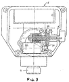
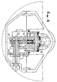
- FIG. 1 illustrating a mixing battery 1 having hot and cold taps 3 and 4 a box like body 5 on top of which is mounted a spout 6 and water outlet 7. As can be seen in Fig. 2, 3 and 4.
- Water pressure at the inlet 9 of the mixing battery 1 passes through an aperture 10 in a diaphragm 11, into a the rear pressure chamber 13 and causes the diaphragm to be secured to its seat 15 preventing the water passage, to spout 6.
- the release of the pressure from the rear pressure chamber 13 is performed by means of a pilot valve 14 and pressure relief channels 17 which cause the pressure at the inlet 9 to be higher than the one at the rear pressure chamber 13, hence the diaphragm 11 will rise from its seat and open the passage for the water to the spout 6.
- pilot valve 14 is activated via stem 16 by means of a small electric motor 20, on which is keyed a gear 21 which mash with gear 22 and the excenter 23 which are keyed on axis 24.
- the excenter 23 is mounted within a follower 25 which transforms the reloving of the excenter 23 to forward and backwards linear movement.
- the pilot valve 14 is connected to the follower 25 via stem 16 thus moves along side the follower so that the forward movement causes it to enter into the water passage 18 and consequently its blocking, while its backward movement causes its retrieving from the water passage 18 and the opening thereof, thus releasing the pressure from chamber 13.
- a 9V battery 30 is placed in compartment 29 supplies eletric power to the motor and the electronic port (to which reference will be made).
- the revolving of the motor in two directions as required is created by the changing of polarity.
- knob 51 which is connected to the free end of axis 24 is turned thus it would bring pilot valve to its "open" position.
- a member 53 being part of knob 51 would turn.
- a magnet 54 is mounted within member 53 and in line with a switch 55. Switch 55 being part of the electric circuit of the assembly, thus the turning of knob 51 would bring said switch to its "break" position.
- Fig. 5 illustrates a faucet where the assembly is mounted within the faucet.
- Fig. 6 The electrical and electronic operation is illustrated in Fig. 6. As mentioned before the voltage supply is fed from 9 volt battery 30 and generates current for the various circuits, for the driver circuit 31 and to the motor driver 34. Amplifier 35 and comparator 6 receive 9 volt current just before projecting a pulse. This period of time is necessary for the receiver to be able to receive generated pulse.
- the low battery detector 37 also operates on these pulses for the same reason so as to save energy. All logic circuits receive a current between 3.5 to 5.5 volts required for the function.
- the oscillator 38 oscillates in an independent manner at a frequency wave of 4hz and activates the pulses by means of driver 31 and the I.R.LED's.
- the control line 40 activates the amplifier 35 and comparator 36.
- the control line 41 controls the comparison between the generated pulse transmitted and the received pulse 42.
- the driver 31 supplies current to the I.R.LED's for a short period of approximately 3 micro seconds at each time a "command" is received from the oscillator 38 or from the MCU 43.
- the I.R.LED's source generate radiation, the wavelength of which is approximately 880 nanometer, the light intensity and pulse width as required by the current flowing therethrough.
- the detector 44 is a silicon detector adapted to receive radiation generated in accordance with the wavelength of the sources.
- the amplifier 35 is designed to amplify the short pulses received from detector 44. Special emphasis is given to the requirement that the amplifier will be connected to the current source for only a short period of time.
- the comparator 36 is designed to compare the signal to the voltage threshold determined by the MCU.
- the threshold is being determined by the MCU according to the instantaneous mode of operation while open the scattering from the water stream has to be taken into account and to the surroundings.
- the faucet can "learn” its surroundings and adapt the threshold valve to it.
- the constant presence of a highly reflective object in the field of view (like a white dish) will, for example, cause an increase of the threshold valve.
- the gate enables the timing of the pulses which are received and amplified.
- the MCU 43 in being activated each time a digital signal is received at its INT.
- the MCU neutralizes the oscillator 38 by means of line 45 and drives the LEDs at a repetition rate much higher than in the usual mode of operation to verify the presence of an "activating object".
- the MCU calculates the statistics of the detected signals - a verification is declared only in the case that a reflected signal has been detected for each limited pulse. In such a case an "open" procedure is activated and an activating pulse is sent to the electric motor.
- the "threshold learning mechanism” adapts the threshold to be just below the accumulated reflection signal from the activating object and the water stream. If no reflection signals are received for a certain period of time, a "close” procedure is implemented and a short pulse is sent via line 48 to which activate the motor to close the faucet.
- the MCU then performs a procedure of adapting the threshold to the constant reflections from objects present in the detector field of view.
- IR transmitter 70 and receiver 72 are both mounted in body 5.
- a geometrical overlap zone Z is defined. Only objects that enter into this zone Z will activate the water flow, as described above.
- Fig. 8 illustrates a prefered embodiment.
- the infrared sensing means 70 installed on the spout and a receiver 72 equipped with an objective lens is mounted in the body.
- the radiation conus and the receiver field-of-view define an overlap volume X such that only objects inside this volume will scatter light into the receiver and activate the faucet.
- Fig. 9 illustrates a manner according to which a large activation volume X is defined and still a strict geometrical definition of this activation zone is maintained.
- a plurality of LEDs 70 and a plurality of eceivers are used to geometrically cover the required zone.
- AUTOMATIC MODE In this mode of operation an object inserted into the activation zone triggers the water flow. When this object is removed from the activation zone the water flow stops. This is the "normal" operation mode applicable for hand and dish washing.
- SEMI-AUTOMATIC MODE In this mode an object inserted into the activation volume activates the water flow as above. The water flow does not stop when the object is removed from the zone. In order to stop the water flow object must penetrate the activation zone for the second time. This "on/off zone" may be localized in a region that is usually not accessible when performing usual dish washing tasks. The semi-automatic mode of operation is required when handling black or specular objects or when soaping the dishes or cleaning the basin.
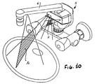
- Fig. 10 relates to the prefered embodiment which employs a combination of the two above mentioned embodiments.
- both automatic and semi-automatic modes of operation are required for every faucet installed in a kitchen basin and sometimes in bath basins as well.
- the automatic mode is activated
- the semi-automatic modes is chosen while saponizing dishes, cleaning the basin or washing black or specular dishes.
- a special distinction between the activation zones for the two modes of operation is implemented: the volume beneath the faucet outlet X is used as the "automatic zone” while the volume near the faucet Z is used as the "semi-automatic" zone.
- the system distinguishes between the two modes using one of the following means:
Landscapes
- Health & Medical Sciences (AREA)
- Life Sciences & Earth Sciences (AREA)
- Engineering & Computer Science (AREA)
- Hydrology & Water Resources (AREA)
- Public Health (AREA)
- Water Supply & Treatment (AREA)
- Domestic Plumbing Installations (AREA)
Applications Claiming Priority (2)
| Application Number | Priority Date | Filing Date | Title |
|---|---|---|---|
| IL105133A IL105133A0 (en) | 1993-03-22 | 1993-03-22 | Electronically operated faucet including sensing means |
| IL10513393 | 1993-03-22 |
Publications (1)
| Publication Number | Publication Date |
|---|---|
| EP0617175A1 true EP0617175A1 (de) | 1994-09-28 |
Family
ID=11064642
Family Applications (1)
| Application Number | Title | Priority Date | Filing Date |
|---|---|---|---|
| EP94104494A Withdrawn EP0617175A1 (de) | 1993-03-22 | 1994-03-22 | Elektronisch geregelter Wasserhahn mit Sensormittel |
Country Status (3)
| Country | Link |
|---|---|
| US (1) | US5549273A (de) |
| EP (1) | EP0617175A1 (de) |
| IL (1) | IL105133A0 (de) |
Cited By (6)
| Publication number | Priority date | Publication date | Assignee | Title |
|---|---|---|---|---|
| FR2761446A1 (fr) * | 1997-03-28 | 1998-10-02 | Celec Conception Electronique | Robinet d'eau automatique a commande sans contact |
| US5918855A (en) * | 1993-12-20 | 1999-07-06 | Toto Ltd. | Automatic faucet |
| WO2009059587A1 (de) * | 2007-11-06 | 2009-05-14 | Micas Ag | Verfahren und anordnung zur identifikation von szenen in einem erfassungsraum |
| GB2457141A (en) * | 2008-02-01 | 2009-08-12 | Kibuts Glil Yam | Automatic faucet |
| EP3730705A1 (de) | 2017-05-26 | 2020-10-28 | Neoperl GmbH | Sanitärventil |
| EP3239416B1 (de) | 2016-04-29 | 2021-06-09 | A. u. K. Müller GmbH & Co. KG | Armaturauslass und armatur |
Families Citing this family (61)
| Publication number | Priority date | Publication date | Assignee | Title |
|---|---|---|---|---|
| US5297260A (en) * | 1986-03-12 | 1994-03-22 | Hitachi, Ltd. | Processor having a plurality of CPUS with one CPU being normally connected to common bus |
| DE29800536U1 (de) * | 1998-01-16 | 1998-03-05 | A. u. K. Müller GmbH & Co KG, 40595 Düsseldorf | Magnetventil, insbesondere für sanitäre Armaturen |
| US5988588A (en) * | 1998-03-16 | 1999-11-23 | Asloan Valve Company | Control module for battery-operated faucet |
| US6202980B1 (en) | 1999-01-15 | 2001-03-20 | Masco Corporation Of Indiana | Electronic faucet |
| KR100353901B1 (ko) * | 2000-05-24 | 2002-09-27 | 장길용 | 절수용 자동밸브 |
| US6499152B2 (en) * | 2001-01-18 | 2002-12-31 | Geberit Technik Ag | Flush controller |
| US6560790B2 (en) * | 2001-03-06 | 2003-05-13 | Geberit Technik Ag | Flush control |
| US7731154B2 (en) * | 2002-12-04 | 2010-06-08 | Parsons Natan E | Passive sensors for automatic faucets and bathroom flushers |
| US7083156B2 (en) * | 2003-01-16 | 2006-08-01 | Technical Concepts, Llc | Automatic proximity faucet with override control system and method |
| US7174577B2 (en) | 2003-01-16 | 2007-02-13 | Technical Concepts, Llc | Automatic proximity faucet |
| CN1320297C (zh) * | 2003-09-15 | 2007-06-06 | 周敏芳 | 感应式水龙头 |
| US7537023B2 (en) * | 2004-01-12 | 2009-05-26 | Masco Corporation Of Indiana | Valve body assembly with electronic switching |
| US7690395B2 (en) | 2004-01-12 | 2010-04-06 | Masco Corporation Of Indiana | Multi-mode hands free automatic faucet |
| US7104519B2 (en) * | 2004-03-09 | 2006-09-12 | Ultraclenz Llc | Adapter for touch-free operation of gooseneck faucet |
| CA2478578C (en) * | 2004-08-19 | 2013-01-29 | Hygiene-Technik Inc. | Dispenser with sensor |
| US8104113B2 (en) * | 2005-03-14 | 2012-01-31 | Masco Corporation Of Indiana | Position-sensing detector arrangement for controlling a faucet |
| US7614096B2 (en) * | 2005-03-16 | 2009-11-10 | Masco Corporation Of Indiana | Control for an automatic plumbing device |
| US7278624B2 (en) * | 2005-04-25 | 2007-10-09 | Masco Corporation | Automatic faucet with polarization sensor |
| US7472433B2 (en) * | 2006-01-05 | 2009-01-06 | Masco Corporation Of Indiana | Method and apparatus for determining when hands are under a faucet for lavatory applications |
| WO2008051973A1 (en) | 2006-10-24 | 2008-05-02 | Bradley Fixtures Corporation | Capacitive sensing for washroom fixture |
| US9243392B2 (en) | 2006-12-19 | 2016-01-26 | Delta Faucet Company | Resistive coupling for an automatic faucet |
| US7806141B2 (en) | 2007-01-31 | 2010-10-05 | Masco Corporation Of Indiana | Mixing valve including a molded waterway assembly |
| CA2676976C (en) | 2007-01-31 | 2015-10-06 | Masco Corporation Of Indiana | Capacitive sensing apparatus and method for faucets |
| WO2008118402A1 (en) | 2007-03-28 | 2008-10-02 | Masco Corporation Of Indiana | Improved capacitive touch sensor |
| US9730557B2 (en) | 2007-05-16 | 2017-08-15 | Ecolab Usa Inc. | Keyed dispensing cartridge with valve insert |
| US8020733B2 (en) * | 2007-05-16 | 2011-09-20 | Ultraclenz, Llc | Keyed dispensing cartridge system |
| US20080283786A1 (en) * | 2007-05-18 | 2008-11-20 | Snodgrass David L | Infrared retrofit faucet controller |
| US8572772B2 (en) * | 2007-09-05 | 2013-11-05 | James L. Wolf | Electronic faucet with voice, temperature, flow and volume control |
| MX2010006473A (es) | 2007-12-11 | 2010-09-22 | Masco Corp | Disposicion de acoplamiento capacitivo para un grifo. |
| US8407827B1 (en) | 2009-07-06 | 2013-04-02 | Adam Michael Friedman | Spatially reactive water system |
| US9057182B1 (en) | 2009-07-06 | 2015-06-16 | Adam Friedman | Spatially reactive water system incorporating a non tactile control module |
| US9032565B2 (en) * | 2009-12-16 | 2015-05-19 | Kohler Co. | Touchless faucet assembly and method of operation |
| US8408517B2 (en) * | 2009-12-29 | 2013-04-02 | Masco Corporation Of Indiana | Water delivery device |
| US8614414B2 (en) * | 2009-12-29 | 2013-12-24 | Masco Corporation Of Indiana | Proximity sensor |
| US8355822B2 (en) * | 2009-12-29 | 2013-01-15 | Masco Corporation Of Indiana | Method of controlling a valve |
| US9057183B2 (en) * | 2010-02-02 | 2015-06-16 | Chung-Chia Chen | Touch free automatic faucet |
| US8418993B2 (en) | 2010-02-02 | 2013-04-16 | Chung-Chia Chen | System and method of touch free automatic faucet |
| US8776817B2 (en) | 2010-04-20 | 2014-07-15 | Masco Corporation Of Indiana | Electronic faucet with a capacitive sensing system and a method therefor |
| US8561626B2 (en) | 2010-04-20 | 2013-10-22 | Masco Corporation Of Indiana | Capacitive sensing system and method for operating a faucet |
| US11091901B2 (en) | 2011-07-13 | 2021-08-17 | Delta Faucet Company | Faucet handle with angled interface |
| US8820705B2 (en) | 2011-07-13 | 2014-09-02 | Masco Corporation Of Indiana | Faucet handle with angled interface |
| USD677367S1 (en) | 2011-09-26 | 2013-03-05 | Chung-Chia Chen | Touch-free faucet |
| USD677366S1 (en) | 2011-09-26 | 2013-03-05 | Chung-Chia Chen | Touch-free faucet |
| EP2823107A4 (de) | 2012-03-07 | 2016-06-15 | Moen Inc | Befestigung für eine elektronische klempnerarmatur |
| WO2013162616A1 (en) * | 2012-04-27 | 2013-10-31 | Intel Corporation | Metrology and methods for detection of liquid |
| US9347207B2 (en) | 2013-03-15 | 2016-05-24 | Chung-Chia Chen | Faucet assembly |
| CN104344047B (zh) | 2013-08-07 | 2017-04-12 | 科勒公司 | 用于龙头的传感器组合件 |
| US9920508B2 (en) | 2014-06-09 | 2018-03-20 | Chung-Chia Chen | Touch-free faucets and sensors |
| JP6242777B2 (ja) * | 2014-09-29 | 2017-12-06 | 株式会社Lixil | 自動水栓およびキッチン |
| US11078652B2 (en) | 2014-12-18 | 2021-08-03 | Delta Faucet Company | Faucet including capacitive sensors for hands free fluid flow control |
| US9702128B2 (en) | 2014-12-18 | 2017-07-11 | Delta Faucet Company | Faucet including capacitive sensors for hands free fluid flow control |
| US10301801B2 (en) * | 2014-12-18 | 2019-05-28 | Delta Faucet Company | Faucet including capacitive sensors for hands free fluid flow control |
| US20170101766A1 (en) * | 2015-10-09 | 2017-04-13 | Spectrum Brands, Inc. | Faucet with Auto-Fill Feature |
| CA2969339C (en) * | 2016-06-03 | 2020-03-24 | Maax Bath Inc. | Electronic faucet |
| DE102016113832A1 (de) * | 2016-07-27 | 2018-02-01 | Blanco Gmbh + Co Kg | Armatur |
| US10569286B2 (en) | 2017-05-08 | 2020-02-25 | Ecolab Usa Inc. | Shaped cartridge dispensing systems |
| US10947708B2 (en) | 2018-02-28 | 2021-03-16 | Kohler Co. | Container filling faucet |
| US11761185B2 (en) * | 2021-10-19 | 2023-09-19 | Xiamen Forbetter Sanitary Ware Co., Ltd. | Two-handle automatic faucet |
| US11686076B1 (en) * | 2022-01-21 | 2023-06-27 | Harda Intelligent Technologies Co., Ltd. | Thermostatic automatic faucet |
| US12493355B2 (en) | 2022-04-14 | 2025-12-09 | Kohler Co. | Touchless plumbing control system |
| US20240076859A1 (en) * | 2022-09-06 | 2024-03-07 | Xiamen Forbetter Sanitary Ware Co., Ltd. | Pull-out automatic faucet |
Citations (6)
| Publication number | Priority date | Publication date | Assignee | Title |
|---|---|---|---|---|
| DE3537678A1 (de) * | 1985-10-23 | 1987-04-23 | Peter Wilfred Auge | Beruehrungslos betaetigbare absperrarmatur fuer fluessigkeiten |
| GB2195763A (en) * | 1986-09-13 | 1988-04-13 | Theodoros Mastichiadis | Water tap |
| GB2206397A (en) * | 1987-07-01 | 1989-01-05 | Chong Lih Electric Industry Co | Photoelectrically-controlled faucet structure |
| WO1990002989A1 (en) * | 1988-09-14 | 1990-03-22 | Chang Hwan Lee | Automatic mixing faucet |
| US5142134A (en) * | 1990-06-22 | 1992-08-25 | Hansa Metallwerke Ag | Method for operating a circuit arrangement |
| DE4218658A1 (de) * | 1991-06-19 | 1992-12-24 | Sloan Valve Co | Batteriebetriebene sensor- und kontrollschaltung |
Family Cites Families (9)
| Publication number | Priority date | Publication date | Assignee | Title |
|---|---|---|---|---|
| US4788998A (en) * | 1981-03-26 | 1988-12-06 | Pepper Robert B | Ultrasonically operated water faucet |
| US4762273A (en) * | 1986-03-07 | 1988-08-09 | Stephen O. Gregory | Electronic faucet with spout position sensing means |
| EP0312781A1 (de) * | 1987-09-21 | 1989-04-26 | Hansa Metallwerke Ag | Berührungslos gesteuerte Sanitärarmatur |
| US4872485A (en) * | 1987-12-23 | 1989-10-10 | Coyne & Delany Co. | Sensor operated water flow control |
| US4894874A (en) * | 1988-03-28 | 1990-01-23 | Sloan Valve Company | Automatic faucet |
| JP2774545B2 (ja) * | 1989-02-07 | 1998-07-09 | 東陶機器株式会社 | 自動水栓装置 |
| US4921211A (en) * | 1989-02-24 | 1990-05-01 | Recurrent Solutions Limited Partnership | Method and apparatus for flow control |
| US5243717A (en) * | 1990-03-16 | 1993-09-14 | Inax Corporation | Human body sensing mechanism for an automatic faucet apparatus |
| US5033715A (en) * | 1990-08-30 | 1991-07-23 | Sing Chiang | Infrared faucet |
-
1993
- 1993-03-22 IL IL105133A patent/IL105133A0/xx unknown
-
1994
- 1994-03-22 US US08/215,740 patent/US5549273A/en not_active Expired - Fee Related
- 1994-03-22 EP EP94104494A patent/EP0617175A1/de not_active Withdrawn
Patent Citations (6)
| Publication number | Priority date | Publication date | Assignee | Title |
|---|---|---|---|---|
| DE3537678A1 (de) * | 1985-10-23 | 1987-04-23 | Peter Wilfred Auge | Beruehrungslos betaetigbare absperrarmatur fuer fluessigkeiten |
| GB2195763A (en) * | 1986-09-13 | 1988-04-13 | Theodoros Mastichiadis | Water tap |
| GB2206397A (en) * | 1987-07-01 | 1989-01-05 | Chong Lih Electric Industry Co | Photoelectrically-controlled faucet structure |
| WO1990002989A1 (en) * | 1988-09-14 | 1990-03-22 | Chang Hwan Lee | Automatic mixing faucet |
| US5142134A (en) * | 1990-06-22 | 1992-08-25 | Hansa Metallwerke Ag | Method for operating a circuit arrangement |
| DE4218658A1 (de) * | 1991-06-19 | 1992-12-24 | Sloan Valve Co | Batteriebetriebene sensor- und kontrollschaltung |
Cited By (6)
| Publication number | Priority date | Publication date | Assignee | Title |
|---|---|---|---|---|
| US5918855A (en) * | 1993-12-20 | 1999-07-06 | Toto Ltd. | Automatic faucet |
| FR2761446A1 (fr) * | 1997-03-28 | 1998-10-02 | Celec Conception Electronique | Robinet d'eau automatique a commande sans contact |
| WO2009059587A1 (de) * | 2007-11-06 | 2009-05-14 | Micas Ag | Verfahren und anordnung zur identifikation von szenen in einem erfassungsraum |
| GB2457141A (en) * | 2008-02-01 | 2009-08-12 | Kibuts Glil Yam | Automatic faucet |
| EP3239416B1 (de) | 2016-04-29 | 2021-06-09 | A. u. K. Müller GmbH & Co. KG | Armaturauslass und armatur |
| EP3730705A1 (de) | 2017-05-26 | 2020-10-28 | Neoperl GmbH | Sanitärventil |
Also Published As
| Publication number | Publication date |
|---|---|
| US5549273A (en) | 1996-08-27 |
| IL105133A0 (en) | 1993-07-08 |
Similar Documents
| Publication | Publication Date | Title |
|---|---|---|
| US5549273A (en) | Electrically operated faucet including sensing means | |
| US5458147A (en) | Device and process for the contactless control of the flow of water in a sanitary appliance | |
| CA2017009C (en) | Solenoid operated faucet | |
| US6202980B1 (en) | Electronic faucet | |
| US5187816A (en) | Automatic flushing device | |
| US5313673A (en) | Electronic flush valve arrangement | |
| US5699833A (en) | Electro-mechanical fluid flow control apparatus | |
| US5095945A (en) | Electronic tapware | |
| US10612221B2 (en) | Intelligent faucet structure based on photoelectric detection device | |
| US20060207019A1 (en) | Control for an automatic plumbing device | |
| US6634618B2 (en) | Water saving automatic valve | |
| CA2557704A1 (en) | Method and apparatus for actuating a self-flushing toilet having a dual threshold sensor | |
| JPS63111383A (ja) | 自動水栓装置 | |
| US20260015842A1 (en) | Tap with hidden ultrasonic transducer | |
| JPH10163025A (ja) | ソレノイド駆動装置とこれを用いた弁装置および自動給水装置 | |
| JPH0483027A (ja) | 自動水栓の制御方法 | |
| JPH0358611B2 (de) | ||
| JP3456101B2 (ja) | 物体検知装置 | |
| JPS63284329A (ja) | 自動水栓装置 | |
| JP3161150B2 (ja) | 物体検知方法 | |
| JPS61262284A (ja) | 水道用給水制御システム | |
| JP3915525B2 (ja) | 自動水栓装置 | |
| JPH0376374B2 (de) | ||
| JPH05295772A (ja) | 後付式自動水栓装置 | |
| JP2590352Y2 (ja) | 自動水栓装置 |
Legal Events
| Date | Code | Title | Description |
|---|---|---|---|
| PUAI | Public reference made under article 153(3) epc to a published international application that has entered the european phase |
Free format text: ORIGINAL CODE: 0009012 |
|
| AK | Designated contracting states |
Kind code of ref document: A1 Designated state(s): AT BE CH DE DK ES FR GB GR IE IT LI NL PT SE |
|
| 17P | Request for examination filed |
Effective date: 19950324 |
|
| 17Q | First examination report despatched |
Effective date: 19950529 |
|
| STAA | Information on the status of an ep patent application or granted ep patent |
Free format text: STATUS: THE APPLICATION IS DEEMED TO BE WITHDRAWN |
|
| 18D | Application deemed to be withdrawn |
Effective date: 19961119 |