EP0617256B1 - Procédé pour déterminer le diamètre d'une circonférence d'une zone ou d'un train de zones et dispositif le mettant en oeuvre - Google Patents
Procédé pour déterminer le diamètre d'une circonférence d'une zone ou d'un train de zones et dispositif le mettant en oeuvre Download PDFInfo
- Publication number
- EP0617256B1 EP0617256B1 EP19930104961 EP93104961A EP0617256B1 EP 0617256 B1 EP0617256 B1 EP 0617256B1 EP 19930104961 EP19930104961 EP 19930104961 EP 93104961 A EP93104961 A EP 93104961A EP 0617256 B1 EP0617256 B1 EP 0617256B1
- Authority
- EP
- European Patent Office
- Prior art keywords
- wheel
- provision
- reception
- diameter
- light sections
- Prior art date
- Legal status (The legal status is an assumption and is not a legal conclusion. Google has not performed a legal analysis and makes no representation as to the accuracy of the status listed.)
- Expired - Lifetime
Links
Images





Classifications
-
- G—PHYSICS
- G01—MEASURING; TESTING
- G01B—MEASURING LENGTH, THICKNESS OR SIMILAR LINEAR DIMENSIONS; MEASURING ANGLES; MEASURING AREAS; MEASURING IRREGULARITIES OF SURFACES OR CONTOURS
- G01B11/00—Measuring arrangements characterised by the use of optical techniques
- G01B11/24—Measuring arrangements characterised by the use of optical techniques for measuring contours or curvatures
- G01B11/245—Measuring arrangements characterised by the use of optical techniques for measuring contours or curvatures using a plurality of fixed, simultaneously operating transducers
-
- G—PHYSICS
- G01—MEASURING; TESTING
- G01B—MEASURING LENGTH, THICKNESS OR SIMILAR LINEAR DIMENSIONS; MEASURING ANGLES; MEASURING AREAS; MEASURING IRREGULARITIES OF SURFACES OR CONTOURS
- G01B11/00—Measuring arrangements characterised by the use of optical techniques
- G01B11/08—Measuring arrangements characterised by the use of optical techniques for measuring diameters
Definitions
- the invention relates to a method for determining a diameter of a circumferential line running through at least one point of a circumferential surface on wheels of wheel sets with a wheel rim or tire profile, and a device for carrying out the proposed method.
- a device with at least one running plane arranged in a measuring range, at least one device containing at least one radiation source for generating reflection surfaces by means of electromagnetic radiation beams on the running surface, sensor or receiving devices for detecting the said reflection surfaces, and a control device. and evaluation device, connected to an output unit, the control and evaluation device being connected both to the receiving devices and to the device for generating the reflection surfaces, and wherein this device and the said receiving devices are arranged relative to one another such that the generation of the reflection surfaces and whose detection is possible within the measuring range.
- the area of the tread in the case of wheels installed in the vehicle can be partially covered by conversions such as sand pipes and brake shoes and thus difficult to access for a measurement and the measurement base can be restricted.
- DE-A-3522809 and EP-A-0208060 describe methods with devices for determining the diameter of wheel sets rolling on rails and installed in the vehicle.
- the throughput time of a wheel is measured in a measuring section defined, for example, by light barriers, and the speed thereof is determined from this.
- the circumferential surface of the wheel is determined within this measuring section or upstream or downstream via contactless distance sensors or laser beams.
- the invention has for its object to propose a method with which the diameter of wheels of wheelsets can be determined so that there is no impairment of the measurement data by lateral offset of the wheels and by crumbling and conversions. Furthermore, a device for carrying out this method is to be proposed.
- any reference line on the wheel that can be reached through the light section can be selected as reference lines running concentrically to the wheel axis.
- reference lines can preferably be placed on the wheel flange of the wheel rim or tire profile, since this area is the least worn and easily accessible, or is not covered by sand pipes or conversions.
- two receiving devices are arranged in relation to the beam trees assigned to them so that their optical axes intersect approximately at right angles. It is hereby achieved that the light sections generated by the beam trees can be picked up by the receiving devices from a favorable recording position and thereby minimizing distortions.
- one radiation source or at least one radiation source with at least two beam splitters and at least one deflection mirror is provided for generating the beam trees.
- one or more radiation sources can be used, depending on requirements and space.
- a radiation source with several beam splitters and deflecting mirrors it is possible to create a compact, inexpensive unit that can be provided, for example, as a module.
- two receiving devices are arranged so that they each pass with their optical axes a distance between the light sections of a largest wheel to be measured and a smallest wheel to be measured approximately in the middle. It is hereby achieved that the recordings of the light sections are received with good sharpness by the receiving devices over the entire recording area or in the area of the distance.
- a radiation source or a beam tree for generating a light section is arranged so that its optical axis runs approximately radially to the wheel axis and perpendicular to the running plane and that an associated receiving device is arranged so that its optical axis forms an acute angle with the optical axis of the radiation source.
- Figure 1 shows the schematic structure of the device according to the invention from a side view.
- a smallest wheel 3 to be measured and a largest wheel 3 'to be measured are shown here.
- a wheel 3, 3 'of a wheel set (not shown in more detail) can move, for example in a rolling manner.
- the wheel 3, 3 ' is in a suitable measuring position in which the light sections 37, 37', 38, 40, 40 'are generated by the radiation sources 4, 4', 7 and for the diameter determination by the receiving devices 6, 6 ', 14 can be included.
- Reaching the measuring position can be determined using mechanical or optical sensors, for example.
- the measuring position is reached when, for example, the contact point 10 lies in the optical axis 12 of the radiation source 7. This is the case when the receiving device 14 first acquires an image.
- a radiation source 4,4 'for generating light sections 37,37', 40,40 ' for example on a wheel flange 5.5' of the wheel 3.3 ', in such a way that the cross section of the Flange top 5.5 'is detected by the light section 37.37', 40.40 '.
- the radiation sources 4, 4 ' are arranged on both sides of a plane 8, which is perpendicular to the running plane 2 and in which the wheel set axis lies in the measuring position, such that their optical axes 19, 19' run the running plane 2 at known, acute angles 27, 27 ' to cut.
- the Radiation sources 4, 4 ' can be designed, for example, as a laser.
- the receiving devices 6, 6 'assigned to the radiation sources 4, 4' are arranged on both sides of the plane 8 mentioned between the radiation sources 4, 4 '.
- a third radiation source 7 is arranged approximately centrally between the receiving devices 6, 6 'in such a way that its optical axis 12 is perpendicular to the running plane.
- the third radiation source 7 generates a light section 38 on the wheel rim or on the tire profile 13, starting from the inner wheel end face 11 shown in FIG. 2 when the wheel is in the measuring position.
- This radiation source 7 can also be designed as a laser.
- a receiving device 14 is also assigned to the radiation source 7.
- the profile contour of the wheel rim or wheel tire profile 13 illuminated with the light section 38 is fed to this receiving device 14 via a deflecting mirror 15 in such a way that the optical axis 12 of the radiation source 7 and the optical axis 16 of the receiving device 14 meet at an acute angle 17. Particularly when the acute angle 17 is large, the light section 38 can be recorded and imaged almost undistorted by the receiving device 14.
- the corresponding receiving devices 6, 6 ' are arranged such that their optical axes 18, 18' the optical axes 19, 19 'of the radiation sources 4, 4' assigned to them cross at approximately a right angle 20, 20 '.
- CCD cameras can be provided as receiving devices 6, 6 ', 14.
- the radiation sources 4, 4 ', 7 and the receiving devices 6, 6', 14 assigned to them can be arranged below the running surface 2 formed by a rail 1.
- the radiation sources 4, 4 'for generating the light sections 37, 37', 40, 40 'on the flanged tip 5.5' are arranged at known distances 21, 21 'from the running plane 2 below this and at a known distance 22 from one another.
- the third radiation source 7 for generating a light section 38 on the wheel rim or tire profile 13 is arranged in the middle of this distance 22.
- the receiving devices 6, 6 'are the third on both sides Radiation source 7 is arranged at known distances 23, 23 'from the other radiation sources 4,4' and at known distances 24, 24 'from running plane 2.
- the receiving devices 6, 6 ', 14 are arranged in relation to the rail 1 in such a way that their optical axes 12, 18, 18' have known distances 25, 26 to the running plane 2 and to one another.
- a receiving device 14 for receiving the wheel rim or tire profile 13 a plurality of receiving devices can also be provided, as shown in FIG.
- the optical axes 18, 18 'of the radiation sources 4.4' run centrally through the distances 41, 41 'between the light sections 37 and 37' and 40 and 40 ', in each case between the largest wheel 3' and the smallest Wheel 3.
- light sections in the area of the distances 41, 41 ' can be received with good sharpness by the receiving devices 6, 6'.
- All radiation sources 4, 4 ', 7 and all receiving devices 6, 6', 14 are, as further shown in FIG. 1, connected to a computer 30 via transmission means 28, 29, 31, 32, 33, 34.
- An output unit 36 is connected to the computer 30, which serves as a control and evaluation unit, via a further transmission means 35.
- a measuring process according to the method according to the invention is initiated in that the wheel 3, 3 'or a wheel set (not shown in FIG. 1) rolls, for example in the direction of arrow 39, on the running level 2 of the rail 1 into the switched-on and thus ready-to-operate device according to the invention. Then in the measuring position shown in FIG coincides, the measurement process is triggered.
- the measurement process can be triggered by a rail switch, not shown in FIG. 1, which is actuated by the wheel itself. This could also be triggered by the first detection of a light section by the receiving device 14.
- the computer 30 coordinates the further course of the measurement process and activates at least the radiation sources 4 via the transmission means 28, 29, 31, 32, 33, 34.
- the radiation sources 4, 4 ', 7 then produce light sections 37, 37', 38 on the wheel flange tip 5.5 'and on the wheel rim or tire profile 13.
- the lines 6, 6', 14 receive the lines reflected as diffusely visible light sections 37, 37 ', 38; 40, 40' recorded in position and shape and sent to the computer 30 via the transmission means 31, 32, 33 and stored there.
- Figure 2 shows the device for performing the method according to the invention from the view in the direction Z or in the running direction of the wheel 3.
- the wheel 3 is in the measuring position.
- the light sections 37, 37 ', 38 are generated on the wheel flange tip 5 and on the wheel rim or wheel tire profile 13 by the radiation sources 4, 4', 7 which are not shown in FIG.
- the light sections 37, 37 ' are received and imaged by the receiving device 6 and the receiving device 6' (not shown in FIG. 2), and the light section 38 via a deflecting mirror 15 by the receiving device 14. From the receiving devices 6, 6 ', 14 are now the light sections shown 37, 37 ', 38, as already described, forwarded to the computer 30, not shown in FIG.
- FIG. 11 shows a side view of the schematic structure of a device according to the invention, in which radiation sources are replaced by beam splitters 91, 92 and deflection mirrors 90. Only one radiation source 93 for generating a laser beam 94 is then required.
- the laser beam 94 generated by the radiation source 93 strikes the beam splitter 91 and is divided into the beam tree 89, with the optical axis 19 'and the laser beam 94'.
- This laser beam 94" strikes the deflecting mirror 90, is deflected and forms the beam tree 88, with the optical one Axis 19.
- the receiving devices 6, 6 ', 14 have remained and the relative distances between the components of the device required for the mode of operation of the device correspond to the relative distances of a device according to Figure 1.
- the triggering of a measuring process takes place with this device according to Figure 11 in the same way as in the case of a device according to Figure 1, for example by triggering a rail switch (not shown)
- the computer 30 coordinates the further course of the measuring process and activates the radiation source 93 and the associated ones via the transmission means 31, 32, 33.95 Receiving devices 6, 6 '.
- the radiation source 93 then generates using lasers beam 94.94 ', 94' 'beam splitter 91.92 and deflecting mirror 90 as well as beam trees 87.88.89 the light sections 37.37', 38 on the wheel flange 5.5 'and on the wheel rim or tire profile 13.
- the other The functional sequence then takes place as in the case of a device according to FIGS. 1 and 2.
- FIGS. 3 and 4 show the illustrations 42, 43 of the light sections 37, 37 'of the wheel flange tip 5 shown in FIG. 2 and in FIG. 5 the illustration 44 of the light section 38 of the wheel rim or wheel tire profile 13.
- the computer 30 shown schematically in FIG. 1 determines from FIGS Flange top 5 points 46, 47 on flanged top 5, which have the greatest radial distance 45 from wheel axis 9.
- the computer 30 determines from the illustration 44 of the wheel rim or tire profile 13 the point 48 on the wheel flange 5, which likewise has the greatest radial distance 45 from the wheel axis 9.
- points 46, 47, 48 are each defined by a tangent 51, 51 ', 51 "which runs parallel to the wheel axis and which bears against the illustrations 42, 43, 44 (FIGS. 3 to 5).
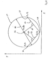
- the points 46, 47, 48 are located on the intersection of a plane 49 perpendicular to the wheel axis 9 and the tangents 51, 51 ', 51 ". From the points 46, 47, 48 defined in this way, the circumferential line 57 shown in FIG. 6 of the flange diameter 60 shown in FIG. 2 can now be calculated by the computer 30 (FIG. 1).
- the points 46, 47, 48 are arranged by the computer 30 in a right-angled coordinate system, specifying the respective x, y coordinates.
- point 46 receives the coordinates x1, y1, point 48 the coordinates x2, y2 and point 47 the coordinates x3, y3.
- the points 46 with 48 and 47 with 48 are connected by the chords 52, 53.
- the gradient of the respective chord can now be calculated with the aid of the coordinates, and the gradients of normal perpendiculars 54, 55 on the chords 52, 53 can in turn be calculated from the gradients which the chords have.
- the center perpendicular 54, 55 intersect at the center 56 of the circle described by the circumferential line 57.
- the coordinates xm, ym of the center point 56 can also be calculated.
- the twice the distance of the center point 56 from one of the points 46, 47, 48 is now the desired diameter of the circle described by the circumferential line 57, which here is equal to the flange diameter 60.
- the measuring circle diameter 59 shown in FIGS. 2 and 5 can be calculated.
- the flange height 61 is twice the flange diameter 60, which is determined by the distance between the intersection of the measuring circle plane 58 with the wheel flange or
- Tire profile 13 and the flange diameter 60 is defined deducted. Wheel flange diameter 60 minus twice wheel flange height 61 results in measuring circle diameter 59.
- a cross-sectional plane on the wheel that runs through the flange diameter 60 was used as the reference line.
- any other cross-sectional plane that is laid through the wheel flange is also suitable as a reference line.
- diameters other than the measuring circle diameter 59 can also be calculated. To do this, it is only necessary to determine the respective flange height 61 at the point on the wheel rim or tire profile 13 that lies in the plane on the wheel whose diameter is to be calculated. A similar procedure can be followed if a different reference line on wheel 3 is selected as the reference line instead of the wheel flange. Of course, the diameter of the reference line can also be calculated in a different way than described here.
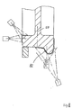
- FIG. 7 shows a reference line formed from an outer wheel end face 67 and an inner cylinder surface 69, which is the measuring surface for the wheel tire thickness in the case of wheels with wheel tires.
- the actual reference line should be the edge 70.
- the outer wheel end face 67 and an inner cylinder surface 69 are illuminated by a radiation source 71, the optical axis 72 of which is arranged at a known angle 73 to the outer wheel end face 67, and a light section 74 is applied such that when this light section 74 is received by a receiving device 75 the Edge 70 can be imaged by the receiving device 75.
- the receiving device 75 can be arranged with its optical axis 76 perpendicular to the outer wheel face 67 or at any other known angle to the wheel face 67.
- edge 70 is detected.
- the edge 70 is a reference line is simple ensures that the reference line lies in a cross-sectional plane to the wheel axis 9.9 '.
- a total of three exposures are necessary.
- FIG. 7 only one image of a light section 74 of the edge 70 is shown.
- the inner wheel end face 11 and a wheel flange groove 65 are illuminated at least up to the measuring circle plane 58 by the light sections 77, 78 which are emitted by the radiation sources 79, 80 generated and received by the receiving device 81.
- the relative position of the radiation sources 71, 79, 80 relative to one another and to the receiving devices 75, 81 is known, radial distances from the edge 70 to selected points on the wheel rim or tire profile 13 can be calculated.
- the position of the measuring circle plane 58 can be easily defined, starting from the light section 77, on the inner wheel face 11 of the wheel.
- FIG. 8 shows a similar arrangement of the light sections to that of FIG. 7. Only the light sections 77 and 78 are combined in FIG. 8 to form a light section 82 and are led to the measuring circle level 58 without interruption.
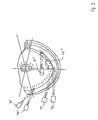
- FIG. 9 is a supplementary illustration to FIG. 7.
- only one radiation source 71 for generating a light section at the edge 70 is shown with the associated receiving device 75.
- FIG. 9 also shows the remaining radiation sources 71 ′, 71 ′′ not shown in FIG. 7 with the receiving devices 75 ′, 75 ′′ assigned to them.
- FIG. 10 shows an embodiment of the device according to the invention in which the optical axis 12 of the radiation source 7, which produces the light section 38 on the wheel rim or on the wheel tire profile 13, at an acute angle 83 to the running plane 2 and through the contact point 10 runs.
- the receiving device 14 is arranged so that its optical axis 16 on the optical axis 12 of the radiation source 7 at the largest possible acute angle 17 hits. With such a position of the optical axis 12 of the radiation source 7, the wheel rim or wheel tire profile 13 to be recorded is not shown radially to the wheel axis 9, 9 '. A calculation of diameters on the circumference of the wheel 3 or the flange diameter 60 is nevertheless possible.
- the center point or the center line of the wheel 3 passing through the center point is also defined and the coordinates xm, ym (FIG. 6) are known. Since the coordinates can also be determined for further points of the light section 38 on the wheel rim or tire profile 13, the profile line can be simulated so that it corresponds to a light section radially to the wheel axis 9, 9 ', as shown in FIG. 1.
- the calculated diameters can be printed out by the output unit or displayed on a screen.
Landscapes
- Physics & Mathematics (AREA)
- General Physics & Mathematics (AREA)
- Length Measuring Devices By Optical Means (AREA)
- Length Measuring Devices With Unspecified Measuring Means (AREA)
- Pinball Game Machines (AREA)
Claims (7)
- Procédé de calcul d'un diamètre d'une ligne circonférentielle passant par au moins un point d'une surface circonférentielle située sur des roues faisant partie d'essieux montés avec un profil de jante ou de bandage, selon lequel- on détermine ou définit sur la roue (3,3') une ligne de réference concentrique à un essieu (9,9'),- dans le sens circonférentiel de la ligne de référence et de façon décalée, on place simultanément au moins trois coupes optiques (37,37',38,40,40') formant chacune un point d'intersection en coupant la ligne de référence,- chaque point d'intersection est enregistré par une caméra adjointe,- la position relative de ces points d'intersection des coupes optiques avec la ligne de référence est calculée à partir des données d'enregistrement par des dispositifs de réception (6,6',14) adjoints, et ce dans un système de référence défini et en tenant compte des lois de projection,- relativement à ce système de référence, on définit la position d'au moins un point (46,47,48) sur la ligne circonférentielle (57) du diamètre à calculer,- sur la base de la position relative des points d'intersection des coupes optiques avec la ligne de référence, on détermine la position de la ligne médiane (56) de l'essieu (9,9') par rapport à ce système de référence ainsi que la distance relative entre ce système et la ligne circonférentielle (57) voulue afin de calculer le diamètre de cette ligne circonférentielle (57).
- Dispositif d'application du procédé de la revendication 1 avec au moins un plan de roulement (2) disposé dans un champ de mesure, un dispositif comprenant au moins un source de rayonnements (4,4',7;93) avec des moyens (90,91,92) permettant de générer au moins trois arbres de rayonnement (87,88,89) pour produire au moyen de faisceaux de rayons trois coupes optiques (37,37',38,40,40') sur la bande de roulement d'une roue (3,3'), des dispositifs de détection et de réception (6,6',14) pour enregistrer les coupes optiques (37,37',38,40,40') indiquées ainsi qu'un dispositif de commande et d'analyse (30) relié à une unité de sortie (36), le dispositif de commande et d'analyse (30) étant relié aussi bien aux dispositifs de réception (6,6',14) qu'au dispositif (4,4',7;90,91,92,93) de génération des coupes optiques (37,37',38,40,40') et ce dernier étant disposé par rapport aux dispositifs de réception (6,6',14) mentionnés de manière à ce que la génération des coupes optiques (37,37',38,40,40') et leur analyse puisse se faire à l'intérieur du champ de mesure,
caractérisé en ce qu'on prévoit un palpeur (7,14), relié au dispositif de commande et d'analyse (30), qui détermine le moment où la roue (3,3') atteint une position de mesure et en ce que l'unité de commande et d'analyse (30) est étudiée pour mémoriser simultanément les trois coupes optiques (37,37',38,40,40') enregistrées par les dispositifs de réception (6,6',14) sur la bande de roulement de la roue (3,3') lorsque la roue (3,3') atteint la position de mesure, et ce de manière à déterminer le diamètre de la roue. - Dispositif selon la revendication 2 caractérisé en ce que deux dispositifs de réception (6,6') sont disposés par rapport aux moyens leur étant adjoints pour la génération d'arbres de rayonnement (87,88,89) de manière à ce que leurs axes optiques (18,18',19,19') se coupent à peu près à angle droit.
- Dispositif selon les revendications 2 et 3 caractérisé en ce que deux dispositifs de réception (6,6') sont disposés de manière à ce que leurs axes optiques (18,18') passent à peu près au centre d'une distance (41,41') séparant les coupes optiques (37,37',40,40') d'une roue plus grande (3') à mesurer et celles d'une roue plus petite (3) evant également être mesurée.
- Dispositif selon la revendication 2 caractérisé en ce qu'on prévoit une source de rayonnement (4,4',7) respective pour générer les arbres de rayonnement (86,87,88).
- Dispositif selon la revendication 2 caractérisé en ce qu'on prévoit au moins une source de rayonnement (93) avec au moins deux lames séparatrices (91,92) et au moins un miroir de déviation (90) pour générer les arbres de rayonnement (87,88,89).
- Dispositif selon les revendications 2 à 4 caractérisé en ce qu'une source de rayonnement (7) ou un arbre de rayonnement destiné à la génération d'une coupe optique (38) est disposé de manière à ce que son axe optique (12) s'étende à peu près radialement par rapport à l'essieu (9,9') et verticalement par rapport au plan de roulement (2) et en ce qu'un dispositif de réception (14) lui étant adjoint est placé de manière à ce que son axe optique (16) forme un angle aigu (17) avec l'axe optique (12) de la source de rayonnement (7) ou de l'arbre de rayonnement (87).
Priority Applications (4)
| Application Number | Priority Date | Filing Date | Title |
|---|---|---|---|
| EP19930104961 EP0617256B1 (fr) | 1993-03-25 | 1993-03-25 | Procédé pour déterminer le diamètre d'une circonférence d'une zone ou d'un train de zones et dispositif le mettant en oeuvre |
| ES93104961T ES2106213T3 (es) | 1993-03-25 | 1993-03-25 | Procedimiento para la determinacion del diametro de una linea periferica en ruedas de pares de ruedas y dispositivo para la ejecucion del procedimiento. |
| DE59307343T DE59307343D1 (de) | 1993-03-25 | 1993-03-25 | Verfahren zur Ermittlung eines Durchmessers einer Umfangslinie an Rädern von Radsätzen und Einrichtung zur Durchführung des Verfahrens |
| DK93104961T DK0617256T3 (da) | 1993-03-25 | 1993-03-25 | Fremgangsmåde til fastsættelse af en periferilinies diameter på hjul af hjulsæt og anordning til udøvelse af fremgangsmåden |
Applications Claiming Priority (1)
| Application Number | Priority Date | Filing Date | Title |
|---|---|---|---|
| EP19930104961 EP0617256B1 (fr) | 1993-03-25 | 1993-03-25 | Procédé pour déterminer le diamètre d'une circonférence d'une zone ou d'un train de zones et dispositif le mettant en oeuvre |
Publications (2)
| Publication Number | Publication Date |
|---|---|
| EP0617256A1 EP0617256A1 (fr) | 1994-09-28 |
| EP0617256B1 true EP0617256B1 (fr) | 1997-09-10 |
Family
ID=8212739
Family Applications (1)
| Application Number | Title | Priority Date | Filing Date |
|---|---|---|---|
| EP19930104961 Expired - Lifetime EP0617256B1 (fr) | 1993-03-25 | 1993-03-25 | Procédé pour déterminer le diamètre d'une circonférence d'une zone ou d'un train de zones et dispositif le mettant en oeuvre |
Country Status (4)
| Country | Link |
|---|---|
| EP (1) | EP0617256B1 (fr) |
| DE (1) | DE59307343D1 (fr) |
| DK (1) | DK0617256T3 (fr) |
| ES (1) | ES2106213T3 (fr) |
Families Citing this family (4)
| Publication number | Priority date | Publication date | Assignee | Title |
|---|---|---|---|---|
| JP3615980B2 (ja) * | 2000-02-14 | 2005-02-02 | 三菱電機株式会社 | 車輪測定装置 |
| DE102008062589A1 (de) * | 2008-12-16 | 2010-06-17 | Ghh Radsatz Service Gmbh | Verfahren zur berührungslosen dynamischen Erfassung des Durchmessers eines Schienenfahrzeugrades |
| CN105292179A (zh) * | 2015-10-13 | 2016-02-03 | 东莞市诺丽电子科技有限公司 | 轮缘尺寸检测方法 |
| DE102016113888A1 (de) * | 2016-07-27 | 2018-02-01 | AuE Kassel GmbH | System und Verfahren zum Ermitteln von Eigenschaften mindestens eines Rades eines Schienenfahrzeugs |
Family Cites Families (2)
| Publication number | Priority date | Publication date | Assignee | Title |
|---|---|---|---|---|
| EP0208060B1 (fr) * | 1985-06-26 | 1993-06-02 | Wilhelm Hegenscheidt Gesellschaft mbH | Méthode et dispositif pour la détermination de diamètres des roues de paires de roues |
| DE3522809A1 (de) * | 1985-06-26 | 1987-01-02 | Hegenscheidt Gmbh Wilhelm | Verfahren und messanlage zur durchmesserbestimmung der raeder von radsaetzen |
-
1993
- 1993-03-25 ES ES93104961T patent/ES2106213T3/es not_active Expired - Lifetime
- 1993-03-25 EP EP19930104961 patent/EP0617256B1/fr not_active Expired - Lifetime
- 1993-03-25 DK DK93104961T patent/DK0617256T3/da active
- 1993-03-25 DE DE59307343T patent/DE59307343D1/de not_active Expired - Fee Related
Also Published As
| Publication number | Publication date |
|---|---|
| EP0617256A1 (fr) | 1994-09-28 |
| DE59307343D1 (de) | 1997-10-16 |
| DK0617256T3 (da) | 1998-05-04 |
| ES2106213T3 (es) | 1997-11-01 |
Similar Documents
| Publication | Publication Date | Title |
|---|---|---|
| EP0254772B1 (fr) | Méthode de la détermination du diamètre des roues de véhicules sur rail et dispositif pour cela | |
| EP0228500B2 (fr) | Méthode et dispositif pour la mesure sans contact du profil d'une roue des roues d'ensembles de roues de voie ferrée | |
| DE2602001C3 (de) | Vorrichtung zur Überprüfung einer bearbeiteten Oberfläche eines Werkstucks | |
| EP2208015B1 (fr) | Système de tête de mesure pour une machine de mesure de coordonnées et procédé de mesure optique de déplacements d'une sonde du système de tête de mesure | |
| EP0208060B1 (fr) | Méthode et dispositif pour la détermination de diamètres des roues de paires de roues | |
| WO2004085957A1 (fr) | Procede de detection dynamique sans contact du profil d'un solide | |
| DE2917021A1 (de) | Vorrichtung zum messen von innenprofilen eines geschlossenen raumes | |
| DE10143504A1 (de) | Überwachungsverfahren und optoelektronischer Sensor | |
| DE68903400T2 (de) | Vorrichtung und verfahren zum inspizieren der seite eines reifens. | |
| WO2009000727A1 (fr) | Capteur optique pour opérations de positionnement | |
| EP1421430B1 (fr) | Dispositif de balayage | |
| DE102006041821A1 (de) | Verfahren zur relativen Positionierung eines Messgegenstands und eines Kraftfahrzeugs zu einem Messgerät sowie Messgerät und Fahrwerksvermessungseinrichtung | |
| EP3318839A1 (fr) | Système et procédé de détection de caractéristiques d'au moins une roue d'un véhicule ferroviaire | |
| DE102006062447A1 (de) | Verfahren und Vorrichtung zur Erfassung der dreidimensionalen Oberfläche eines Objekts, insbesondere eines Fahrzeugreifens | |
| EP1926968A1 (fr) | Procede pour determiner de maniere dynamique sans contact le profil d'un corps solide | |
| EP0617256B1 (fr) | Procédé pour déterminer le diamètre d'une circonférence d'une zone ou d'un train de zones et dispositif le mettant en oeuvre | |
| DE3913159A1 (de) | Verfahren und vorrichtung zur messung von wellenfoermigen deformationen an wenigstens einer schienenoberseite (schienenlaufflaeche) eines schienenweges | |
| EP2199735A2 (fr) | Procédé de détection dynamique sans contact du diamètre d'une roue de véhicule sur rails | |
| DE60118446T2 (de) | Vorrichtung zur optischen Messung der Räder eines Schienenfahrzeuges | |
| DE3522809C2 (fr) | ||
| DE202016104124U1 (de) | System zum Ermitteln von Eigenschaften mindestens eines Rades eines Schienenfahrzeugs | |
| DE10256123A1 (de) | Verfahren und Vorrichtung zur Ermittlung einer Zustandsgröße, insbesondere des Laufflächenprofils, einer Schiene | |
| DE10256122B4 (de) | Verfahren und Vorrichtung zur Ermittlung wenigstens einer Zustandsgröße einer Rad-Schiene-Paarung | |
| EP1010989A1 (fr) | Méthode et appareil de surveillance de systèmes télémètriques multi-chaines pour véhicules | |
| DE102019111606A1 (de) | Verfahren und Vorrichtung zur Prüfung einer Lauffläche eines Rads eines Schienenfahrzeugs |
Legal Events
| Date | Code | Title | Description |
|---|---|---|---|
| PUAI | Public reference made under article 153(3) epc to a published international application that has entered the european phase |
Free format text: ORIGINAL CODE: 0009012 |
|
| AK | Designated contracting states |
Kind code of ref document: A1 Designated state(s): DE DK ES FR |
|
| 17P | Request for examination filed |
Effective date: 19950313 |
|
| RAP1 | Party data changed (applicant data changed or rights of an application transferred) |
Owner name: HEGENSCHEIDT-MFD GMBH |
|
| 17Q | First examination report despatched |
Effective date: 19960417 |
|
| GRAG | Despatch of communication of intention to grant |
Free format text: ORIGINAL CODE: EPIDOS AGRA |
|
| GRAH | Despatch of communication of intention to grant a patent |
Free format text: ORIGINAL CODE: EPIDOS IGRA |
|
| GRAH | Despatch of communication of intention to grant a patent |
Free format text: ORIGINAL CODE: EPIDOS IGRA |
|
| GRAA | (expected) grant |
Free format text: ORIGINAL CODE: 0009210 |
|
| AK | Designated contracting states |
Kind code of ref document: B1 Designated state(s): DE DK ES FR |
|
| ET | Fr: translation filed | ||
| REF | Corresponds to: |
Ref document number: 59307343 Country of ref document: DE Date of ref document: 19971016 |
|
| REG | Reference to a national code |
Ref country code: ES Ref legal event code: FG2A Ref document number: 2106213 Country of ref document: ES Kind code of ref document: T3 |
|
| REG | Reference to a national code |
Ref country code: DK Ref legal event code: T3 |
|
| PLBE | No opposition filed within time limit |
Free format text: ORIGINAL CODE: 0009261 |
|
| 26N | No opposition filed | ||
| PGFP | Annual fee paid to national office [announced via postgrant information from national office to epo] |
Ref country code: FR Payment date: 20000204 Year of fee payment: 8 |
|
| PGFP | Annual fee paid to national office [announced via postgrant information from national office to epo] |
Ref country code: DE Payment date: 20000207 Year of fee payment: 8 |
|
| PGFP | Annual fee paid to national office [announced via postgrant information from national office to epo] |
Ref country code: ES Payment date: 20000310 Year of fee payment: 8 |
|
| PGFP | Annual fee paid to national office [announced via postgrant information from national office to epo] |
Ref country code: DK Payment date: 20000330 Year of fee payment: 8 |
|
| PG25 | Lapsed in a contracting state [announced via postgrant information from national office to epo] |
Ref country code: DK Free format text: LAPSE BECAUSE OF NON-PAYMENT OF DUE FEES Effective date: 20010325 |
|
| PG25 | Lapsed in a contracting state [announced via postgrant information from national office to epo] |
Ref country code: ES Free format text: LAPSE BECAUSE OF NON-PAYMENT OF DUE FEES Effective date: 20010326 |
|
| REG | Reference to a national code |
Ref country code: DK Ref legal event code: EBP |
|
| PG25 | Lapsed in a contracting state [announced via postgrant information from national office to epo] |
Ref country code: FR Free format text: LAPSE BECAUSE OF NON-PAYMENT OF DUE FEES Effective date: 20011130 |
|
| REG | Reference to a national code |
Ref country code: FR Ref legal event code: ST |
|
| PG25 | Lapsed in a contracting state [announced via postgrant information from national office to epo] |
Ref country code: DE Free format text: LAPSE BECAUSE OF NON-PAYMENT OF DUE FEES Effective date: 20020101 |
|
| REG | Reference to a national code |
Ref country code: ES Ref legal event code: FD2A Effective date: 20030203 |