EP0617280A2 - Verfahren zur Überwachung von wesentlichen Bestandteilen in Plattierungsbädern - Google Patents
Verfahren zur Überwachung von wesentlichen Bestandteilen in Plattierungsbädern Download PDFInfo
- Publication number
- EP0617280A2 EP0617280A2 EP94104325A EP94104325A EP0617280A2 EP 0617280 A2 EP0617280 A2 EP 0617280A2 EP 94104325 A EP94104325 A EP 94104325A EP 94104325 A EP94104325 A EP 94104325A EP 0617280 A2 EP0617280 A2 EP 0617280A2
- Authority
- EP
- European Patent Office
- Prior art keywords
- plating bath
- signal
- major constituents
- solution
- potential
- Prior art date
- Legal status (The legal status is an assumption and is not a legal conclusion. Google has not performed a legal analysis and makes no representation as to the accuracy of the status listed.)
- Granted
Links
Images




Classifications
-
- G—PHYSICS
- G01—MEASURING; TESTING
- G01N—INVESTIGATING OR ANALYSING MATERIALS BY DETERMINING THEIR CHEMICAL OR PHYSICAL PROPERTIES
- G01N27/00—Investigating or analysing materials by the use of electric, electrochemical, or magnetic means
- G01N27/26—Investigating or analysing materials by the use of electric, electrochemical, or magnetic means by investigating electrochemical variables; by using electrolysis or electrophoresis
- G01N27/416—Systems
- G01N27/49—Systems involving the determination of the current at a single specific value, or small range of values, of applied voltage for producing selective measurement of one or more particular ionic species
-
- G—PHYSICS
- G01—MEASURING; TESTING
- G01N—INVESTIGATING OR ANALYSING MATERIALS BY DETERMINING THEIR CHEMICAL OR PHYSICAL PROPERTIES
- G01N27/00—Investigating or analysing materials by the use of electric, electrochemical, or magnetic means
- G01N27/26—Investigating or analysing materials by the use of electric, electrochemical, or magnetic means by investigating electrochemical variables; by using electrolysis or electrophoresis
- G01N27/416—Systems
- G01N27/48—Systems using polarography, i.e. measuring changes in current under a slowly-varying voltage
Definitions
- the present invention relates generally to plating baths and methods for monitoring the major constituents contained therein. More particularly, the method of the present invention relates to a voltammetric analysis technique that provides signal spectra which accurately indicate concentrations of major constituents within the bath. The signal spectra can be used to maintain desired major constituent concentrations within limits in order to ensure optimal plating bath performance.
- a typical plating bath solution is comprised of a combination of several different chemical constituents.
- the specific constituents vary depending upon the type of plating bath, but in general can be broadly divided into what are commonly known as major constituents and trace, or minor, constituents.
- the major constituents are defined as those chemical constituents which are in excess of 5 percent of the total bath volume.
- Trace or minor constituents are defined as those present in smaller quantities, i.e. less than 5 percent of the total volume.
- a major constituent is sulfuric acid, which typically represents about 8 to 12 percent of the total volume.
- the acid copper plating bath might also contain trace constituents such as organic addition agents, degradation products and chemical contaminants, present in much smaller concentrations.
- the concentration levels of both major and trace constituents are important determinants of the quality of the resultant plating deposit. Trace constituent concentrations influence certain characteristics of the plating deposit, including tensile strength, ductility, solderability, uniformity, brightness and resistance to thermal shock. Monitoring and optimization of trace constituents assumes that the major constituent concentrations within the bath are already properly set and maintained. Should the major constituents fall outside of required concentration ranges, however, the bath may fail to satisfactorily perform its plating function. It is therefore important that major constituent concentrations be regularly monitored.
- sulfuric acid content within an acid copper plating bath is determined using titration with sodium hydroxide; chromic acid content within a chromium plating bath is found using reduction titration with excess ferrous ammonium sulfate; free cyanide within a silver-cyanide plating bath is found by titration with silver nitrate; and carbonate within a silver-cyanide plating bath is analyzed by precipitation with barium chloride followed by titration with HCl.
- Major constituent concentrations in other types of plating baths are measured in a similar manner.
- wet chemical analysis methods such as the abode must be performed by highly skilled personnel. Specialized and costly chemical analysis equipment and supplies are required. Furthermore, the delay between drawing samples and receiving measurement results can be anywhere from several hours to several days. It is thus very tedious and expensive to monitor major constituent concentrations using currently available techniques. Moreover, the slow response time of wet chemical analysis limits the extent to which a high quality and high speed plating bath can be continuously maintained.
- the current major constituent monitoring techniques are quite different from real time trace constituent monitoring techniques such as those described in U.S. Patent No. 4,631,116, assigned to the present assignee.
- the method disclosed therein uses voltammetric techniques to produce ac current spectra which vary as a result of changes in the concentration of various trace constituents. Voltammetric methods have been found to produce accurate results in real time for trace constituent analysis. However, voltammetric methods have not yet been considered for use in major constituent analysis. As a result, it is presently necessary to use voltammetric trace constituent measurement techniques in conjunction with the above-described major constituent wet chemical analysis in order to monitor the overall chemistry of the plating bath. The wet chemical analysis cannot be performed with the in-tank electrochemical sensors and other equipment typically used in trace constituent analysis. Two different sets of equipment must therefore be maintained in order to perform major and trace constituent analysis. No integrated measurement system is available which is capable of measuring both major and trace constituents.
- a method for monitoring the concentration of major constituents within a plating bath is provided.
- the present invention is based upon the discovery that voltammetric techniques can be used to accurately monitor major constituent concentrations within a plating bath. Voltammetric techniques have been used for monitoring levels of very low concentration trace constituents, but have heretofore not been considered for measuring major constituents.
- the method of the present invention now makes possible the use of voltammetry to accurately determine major constituent concentrations.
- the method of the present invention involves the steps of applying an electrical signal to a working electrode in contact with the plating bath solution, varying the parameters of the electrical signal, and measuring the response signal.
- the characteristics of the response signal vary in accordance with the major constituent concentration within the solution, and thereby provide an accurate real time indication of major constituent concentration.
- an ac signal superimposed on a dc sweep signal is applied to a working electrode which has been pretreated by a dc potential and is in contact with the plating bath solution.
- the dc sweep signal is varied at a selected sweep rate over a selected voltage range.
- An ac response current signal is thereby produced which includes peaks indicative of the concentration levels of major constituents within the plating bath.
- Various independent electrochemical parameters are varied to maximize the sensitivity of the ac current spectra peaks to particular major constituents.
- the method establishes a set of optimal electrochemical parameters for several exemplary plating baths and their respective major constituents.
- the method eliminates the delay, expense and complexity typically associated with current major constituent analysis methods requiring wet chemical analysis. Specialized chemical equipment and chemical analysis personnel are no longer required. The measurement results are available in real time, which facilitates continuous and efficient control of plating bath chemistry.
- the ac response current includes a readily identifiable peak, the amplitude of which varies with the concentration of the major constituent being measured. The constituent levels within the bath can then be adjusted until the desired optimal concentrations are present.
- the method is easily integrated with known trace constituent measurement methods and equipment, thereby providing an efficient overall plating bath analysis system suitable for monitoring both trace and major constituents.
- the method may be used in conjunction with an in-tank electrochemical sensor so as to eliminate the need to draw a sample of electrochemical solution from the plating bath.
- optimal signal parameters for monitoring the concentrations of major constituents within commonly used acid copper, chromium and silver-cyanide plating baths are provided. Furthermore, the method provides an experimental framework for determining optimal measurement signal parameters for monitoring major constituents in other types of plating baths.
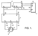
- FIG. 1 is a schematic representation of a preferred embodiment of the voltammetric system used for conducting the method in accordance with the present invention.
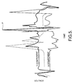
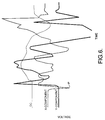
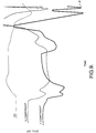
- FIGS. 2-9 show exemplary ac current spectra obtained in accordance with the method of the present invention for exemplary plating baths with various types and concentrations of major constituents.
- the present invention is based upon the discovery that a known voltammetric technique, heretofore considered applicable only to the measurement of trace constituents, can be used to monitor major constituents within a plating bath.
- a known voltammetric technique heretofore considered applicable only to the measurement of trace constituents
- the method of the present invention can be readily adapted for use with other voltammetric techniques.
- the exemplary voltammetric trace constituent monitoring technique to which the method of the present invention is related is described in U.S. Patent No. 4,631,116. The contents of this patent are hereby expressly incorporated by reference.
- major constituents within a plating bath vary depending upon the type of bath, but in general are defined as those constituents which make up in excess of 5 percent of the total plating bath volume.
- the following detailed description will be directed to exemplary major constituents found within the commonly used acid copper, chromium and silver-cyanide plating baths.
- an acid copper plating bath one exemplary major constituent is sulfuric acid, which has a concentration of about 8 to 12 percent of total volume.
- chromic acid which has a concentration of about 225 g/l to 275 g/l CrO3.
- two exemplary major constituents are potassium cyanide and potassium carbonate, with typical concentrations of about 82 g/l to 113 g/l and about 40 g/l to 180 g/l, respectively.
- the method can be used to monitor other major constituents within acid copper, chromium and silver-cyanide plating baths. Furthermore, the method discloses general techniques which are useful for monitoring many other types of plating baths and the major constituents contained therein.
- FIG. 1 illustrates a preferred embodiment of a voltammetric system used to conduct the method of the present invention.
- the plating bath solution is located within an electrochemical cell 9.
- the electrochemical cell 9 is preferably part of an electrochemical sensor submerged within the plating bath.
- a pump can then be used to draw the solution through the cell. This eliminates the need to remove a sample of the solution from the tank, as is currently required by wet chemical analysis techniques.
- a function or waveform generator 5 provides an output 13 which is an ac signal of appropriate frequency and amplitude.
- the ac signal is applied to the external input 23 of a potentiostat 8 and to the reference input 16 of a lock-in amplifier 6.
- the potentiostat serves to superimpose the ac signal applied to its external input 23 upon an appropriate dc voltage sweep signal generated within the potentiostat.
- the dc sweep signal could be supplied by an external function generator.
- the voltammetric signal is simply the one generated within potentiostat 8, upon which the AC is superimposed.
- the combined dc and ac signal output from potentiostat port 25 is then applied to the working electrode 10 in the electrochemical cell 9 via line 28.
- the electrochemical cell 9 also contains a counter electrode 12 and a suitable reference electrode.
- the reference electrode 11 and counter electrode 12 are connected to the accompanying potentiostat ports 26, 27 via lines 29, 30, respectively.
- the electrochemical cell 9 with electrodes 10, 11 and 12 is a sensor design typically used in conjunction with voltammetric techniques. Other sensor designs could also be used.
- the response current is a combined dc and ac signal which varies depending upon the electrochemical processes occurring at the surface of the working electrode 10.
- the electrochemical processes are a function of the major constituent concentrations, and the response current is therefore responsive to these concentrations.
- the response current is applied to the signal input 17 of lock-in amplifier 6 and to the external sweep input 33 of strip chart recorder 7 or to a computerized data acquisition system.
- the lock-in amplifier filters out the DC component in the response signal and isolates out the desired harmonic component in the AC signal. It further resolves the AC harmonic signal into its in-phase and quadrature components.
- the ac harmonic which provides the best diagnostic information is the one which should be selected for measurement. In the exemplary spectra shown in FIGS. 2 through 9 the second harmonic of the ac portion of the response signal provided the best diagnostic information indicative of major constituent concentrations. For other plating baths or major constituents, different harmonics of the ac portion of the response signal may provide better results.
- the in-phase component of the ac portion of the response current is then passed from in-phase output 18 of lock-in amplifier 6 to a display signal input 31 of strip chart recorder 7.
- the quadrature component is passed from quadrature output 19 of lock-in amplifier 6 to a second display signal input 32 of strip chart recorder 7.
- the strip chart recorder displays the in-phase and the quadrature components of the ac portion of the response current as a function of time as shown in FIGS. 2 through 9. These displays represent unique AC response current spectra which indicate the major constituent composition within the plating bath solution.
- the specific equipment used in the exemplary system of FIG. 1 included a Wavetek Model 188 waveform generator, a PAR 273 potentiostat, and a PAR 5208 (or 5210) lock-in amplifier.
- the Wavetek waveform generator is available from Wavetek San Diego, Inc., of San Diego, California and the PAR equipment is available from Princeton Applied Research, of Princeton, New Jersey.
- a number of independent electrochemical parameters include: 1) dc pretreatment voltage and time; 2) type of ac waveform (i.e., sinusoidal, square, triangular, etc.); 3) ac signal amplitude and frequency; 4) dc sweep signal voltage range and sweep rate; 5) ac response signal harmonic measured (i.e., fundamental, second, etc.); 6) ac response signal phase angle measured; and 7) hydrodynamic conditions (i.e., degree of agitation).
- the above parameters were independently varied to determine the optimal parameter settings for monitoring several exemplary major constituents using the preferred voltammetric system of FIG. 1.
- the working electrode is preferably pretreated to remove contaminants at an anodic potential of about 1.5 to 3 volts, for a period of about 5 to 30 seconds.
- a sinusoidal ac waveform with an amplitude of about 20 to 30 mv root mean square (rms) and a frequency of about 50 to 2000 Hz is superimposed on a dc signal which is swept between ⁇ 3 V which encompasses both stripping and plating electrode voltages.
- the DC sweep ranges depend on the specific baths.
- Optimal spectral peak resolution is obtained using the second harmonic of the ac response current, measured using a phase angle offset of about 0 to 45 degrees. Further improvements in monitoring accuracy are obtained by stirring the solution, and maintaining it at an optimum temperature range depending on each plating bath.
- FIGS. 2-9 Examples of the optimization of the exemplary voltammetric system of FIG. 1 to the detection of specific major constituents are described below with reference to FIGS. 2-9. It should be noted that in FIGS. 2-9, the time scale and voltage settings were the same in all cases and are not specifically indicated in the figures. The important point is to compare the figures for the same plating bath solution with particular reference to the height of peak P, as described below.
- One major constituent within an acid copper plating bath is sulfuric acid.
- Optimal ac current spectra of the type shown in FIGS. 2 and 3 were obtained for sulfuric acid concentrations in an acid copper bath using the following system parameters.
- the working electrode Prior to each measurement, the working electrode was pretreated at an anodic potential of about 1.5 to 3 volts for a period of about 10 to 30 seconds.
- An ac signal of about 20 to 30 mv rms amplitude and about 50 to 1500 Hz frequency was superimposed on a dc sweep signal. The dc signal was swept from about 0.4 to - 0.5 volts and reversed to about 0.5 volts at a rate of about 20 to 500 mv/sec.
- the most sensitive spectral peak was found on the quadrature component of the ac response signal second harmonic, measured using a phase angle offset of about 0 to 45 degrees.
- the solution within the electrochemical cell was stirred continuously. The solution was maintained at a temperature of about 25° C.
- an acid copper plating solution containing 10 oz/gal copper sulfate, 20 oz/gal acid, 5 ml/liter carrier, 30 ppm chloride and 5 ml/liter brightener was analyzed using the above system parameters.
- the height of peak P measures about 652 mv relative to a copper reference electrode and corresponds to a concentration of 20 oz/gal of sulfuric acid within the plating bath solution.
- FIG. 3 the effect of increasing the concentration of sulfuric acid within the solution of FIG. 2 to 30 oz/gal is shown.
- the resulting ac response peak P measured 870 mv, thus reflecting the increase in the sulfuric acid content of the solution.
- the method was applied to several other concentrations of sulfuric acid to verify repeatability.
- the sensitivity of the detection of sulfuric acid concentration was about 22 to 30 mv/(oz/gal sulfuric acid). A one oz/gal change in the concentration of sulfuric acid in the solution would thus result in a change in the peak P voltage of about 22 to 30 mv.
- optimal system parameters have been determined for detecting the concentration of chromic acid in an ATOCHEM HCR-840 chromium plating bath.
- An ac signal of about 20 mv to 30 mv rms amplitude and about 100 to 1000 Hz frequency was superimposed on a dc sweep signal.
- the dc signal was swept from about 2.4 to -1.5 volts and reversed to about 2 volts at a rate of about 50 to 100 mv/sec.
- the most sensitive spectral peak was found on the quadrature component of the ac response signal second harmonic, measured at a phase angle offset of about 10 degrees.
- the solution within the electrochemical cell was stirred continuously. The solution was maintained at a temperature of about 60°C.
- the spectra of FIG. 4 result from the application of a signal within the above optimal range to a solution containing 225 g/liter chromium trioxide, 1 g/liter sulfate catalyst, and 4 g/l silicofluoride catalyst.
- the resulting peak P of the quadrature component of the ac portion of the response signal measured 135 mv.
- the resulting peak is well-defined and appears in a portion of the spectrum where there is little other activity.
- the effect of increasing the chromic acid content of the solution of FIG. 4 to 275 g/liter of chromium trioxide, is shown in FIG. 5.
- the height of peak P increases to 180 mv. Applying the method to solutions with different concentrations of chromic acid produced consistent results.
- the sensitivity of this chromic acid detection method is thus about 0.9 to 1.0 mv/(g/liter of chromium trioxide).
- optimal system parameters have been determined for obtaining accurate ac current spectra indicating levels of the major constituent free potassium cyanide within a silver cyanide plating bath.
- An ac signal of about 20 to 30 mv rms amplitude and about 100 to 2000 Hz frequency was superimposed on a dc sweep signal.
- the dc signal was swept from about 0 to -1.6 volts and reversed to about 0.5 volts at a rate of about 100 to 200 mv/sec.
- the most sensitive spectral peak was found on the in-phase component of the ac response signal second harmonic, measured at a phase angle offset of about 0 degrees.
- the solution was maintained at a temperature of about 24 to 26°C.
- a signal within the above-specified optimal range was applied to a silver cyanide plating solution to produce the spectra of FIGS. 6 and 7.
- the solution contained 55 g/liter silver cyanide, 82.5 g/liter total KCN, 55 g/liter free potassium cyanide (82.5 g/liter total potassium cyanide), 150 g/liter K2CO3, 10 g/liter K2SO4, 0.1 ml/liter brightener, and had a pH of 12.3.
- the resultant spectra is shown in FIG. 6.
- the peak P of the in-phase component of the ac response signal appears at the onset of the plating portion of the dc swept signal and measures 75 mv.
- the method of the present invention was applied to determine the concentration of potassium carbonate, a major constituent in a silver cyanide plating bath.
- An ac signal of about 20 to 30 mv rms amplitude and about 200 to 1000 Hz frequency was superimposed on a dc sweep signal.
- the dc signal was swept from about 0 to -1.5 volts where it was held for 10 seconds and reversed to about 0.5 volts at a rate of about 100 to 200 mv/sec.
- the most sensitive spectral peak was found on the quadrature component of the ac response signal second harmonic, measured at a phase angle offset of about 0 to 24 degrees.
- the solution was maintained at a temperature of about 24 to 26°C.
- a signal within the range described above was applied to a silver cyanide plating solution containing 40 g/liter potassium carbonate, 55 g/liter AgCN, 82.5 g/liter total KCN, 10 g/liter K2SO4, and 0.1 ml/l brightener and having a pH of 12.5.
- the resulting spectra are shown in FIG. 8.
- the height of potassium carbonate diagnostic peak P measures 150 mv.
- the effect of increasing the concentration of potassium cyanide within the same solution to 180 g/liter results in the spectra of FIG. 9, where the diagnostic peak P shown measured 320 mv.
- the sensitivity of the method as applied to potassium carbonate within a silver cyanide plating bath is thus about 11 to 15 mv/(g/liter of potassium cyanide).
- the method of the present invention produces reliable and repeatable spectra with easily distinguishable peaks corresponding to the concentration levels of various major constituents.
- These spectra can be used in conjunction with an overall plating bath analysis system which monitors and maintains proper levels of major constituents within various plating baths in real time without removing fluid from the plating tank.
Landscapes
- Chemical & Material Sciences (AREA)
- Life Sciences & Earth Sciences (AREA)
- Health & Medical Sciences (AREA)
- Physics & Mathematics (AREA)
- Chemical Kinetics & Catalysis (AREA)
- Electrochemistry (AREA)
- Molecular Biology (AREA)
- Analytical Chemistry (AREA)
- Biochemistry (AREA)
- General Health & Medical Sciences (AREA)
- General Physics & Mathematics (AREA)
- Immunology (AREA)
- Pathology (AREA)
- Electroplating And Plating Baths Therefor (AREA)
Applications Claiming Priority (2)
| Application Number | Priority Date | Filing Date | Title |
|---|---|---|---|
| US08/037,158 US5336380A (en) | 1993-03-25 | 1993-03-25 | Method of monitoring major constituents in plating baths |
| US37158 | 1993-03-25 |
Publications (3)
| Publication Number | Publication Date |
|---|---|
| EP0617280A2 true EP0617280A2 (de) | 1994-09-28 |
| EP0617280A3 EP0617280A3 (de) | 1996-03-13 |
| EP0617280B1 EP0617280B1 (de) | 1999-09-01 |
Family
ID=21892759
Family Applications (1)
| Application Number | Title | Priority Date | Filing Date |
|---|---|---|---|
| EP94104325A Expired - Lifetime EP0617280B1 (de) | 1993-03-25 | 1994-03-18 | Verfahren zur Überwachung von wesentlichen Bestandteilen in Plattierungsbädern |
Country Status (4)
| Country | Link |
|---|---|
| US (1) | US5336380A (de) |
| EP (1) | EP0617280B1 (de) |
| JP (1) | JP2878588B2 (de) |
| DE (1) | DE69420298T2 (de) |
Families Citing this family (10)
| Publication number | Priority date | Publication date | Assignee | Title |
|---|---|---|---|---|
| US5631845A (en) * | 1995-10-10 | 1997-05-20 | Ford Motor Company | Method and system for controlling phosphate bath constituents |
| US5755954A (en) * | 1996-01-17 | 1998-05-26 | Technic, Inc. | Method of monitoring constituents in electroless plating baths |
| US5753101A (en) * | 1996-08-01 | 1998-05-19 | Ludwig; Frank A. | Method of monitoring constituents in conversion coating baths |
| US20030127334A1 (en) * | 2002-01-08 | 2003-07-10 | Applied Materials, Inc. | Method for determining a concentration of conductive species in an aqueous system |
| EP1540046A4 (de) * | 2002-07-19 | 2007-04-04 | Technic | Verfahren und vorrichtung zur echtzeit berwachung von technischen elektrolyten |
| US20050236280A1 (en) * | 2004-04-27 | 2005-10-27 | Jianwen Han | Methods for analyzing inorganic components of an electrolytic solution, and /or cleaning an electrochemical analytical cell |
| US7951600B2 (en) | 2008-11-07 | 2011-05-31 | Xtalic Corporation | Electrodeposition baths, systems and methods |
| US8992691B2 (en) | 2011-04-05 | 2015-03-31 | International Business Machines Corporation | Partial solution replacement in recyclable persulfuric acid cleaning systems |
| US11579344B2 (en) | 2012-09-17 | 2023-02-14 | Government Of The United States Of America, As Represented By The Secretary Of Commerce | Metallic grating |
| US20150345039A1 (en) * | 2015-07-20 | 2015-12-03 | National Institute Of Standards And Technology | Composition having alkaline ph and process for forming superconformation therewith |
Family Cites Families (1)
| Publication number | Priority date | Publication date | Assignee | Title |
|---|---|---|---|---|
| US4631116A (en) * | 1985-06-05 | 1986-12-23 | Hughes Aircraft Company | Method of monitoring trace constituents in plating baths |
-
1993
- 1993-03-25 US US08/037,158 patent/US5336380A/en not_active Expired - Fee Related
-
1994
- 1994-03-18 EP EP94104325A patent/EP0617280B1/de not_active Expired - Lifetime
- 1994-03-18 DE DE69420298T patent/DE69420298T2/de not_active Expired - Fee Related
- 1994-03-25 JP JP6056311A patent/JP2878588B2/ja not_active Expired - Fee Related
Also Published As
| Publication number | Publication date |
|---|---|
| DE69420298T2 (de) | 2000-05-11 |
| JP2878588B2 (ja) | 1999-04-05 |
| JPH0772120A (ja) | 1995-03-17 |
| EP0617280A3 (de) | 1996-03-13 |
| US5336380A (en) | 1994-08-09 |
| EP0617280B1 (de) | 1999-09-01 |
| DE69420298D1 (de) | 1999-10-07 |
Similar Documents
| Publication | Publication Date | Title |
|---|---|---|
| US4631116A (en) | Method of monitoring trace constituents in plating baths | |
| US5334303A (en) | Electrochemical measurement system | |
| WO1992016825A1 (en) | Method and apparatus for producing electrochemical impedance spectra | |
| AU2478800A (en) | Electrochemical noise technique for corrosion | |
| US5324400A (en) | Electrode preconditioning method for a plating bath monitoring process | |
| US5336380A (en) | Method of monitoring major constituents in plating baths | |
| US5391271A (en) | Method of monitoring acid concentration in plating baths | |
| US5755954A (en) | Method of monitoring constituents in electroless plating baths | |
| EP0598380B1 (de) | Verfahren zur Feststellung von Bestandteilen in Plattierungsbädern | |
| JP2935947B2 (ja) | めっきバス中のトレース成分を選択的に監視する方法 | |
| Ostapczuk et al. | Determination of cadmium, lead and copper in wine by potentiometric stripping analysis | |
| US5298132A (en) | Method for monitoring purification treatment in plating baths | |
| EP0626577B1 (de) | Verfahren zur Überwachung der Ionenkonzentration in galvanischen Bädern | |
| US5753101A (en) | Method of monitoring constituents in conversion coating baths | |
| US5298130A (en) | Method of monitoring major constituents in plating baths containing codepositing constituents | |
| Wang et al. | Stripping potentiometric measurements of copper in blood using gold microelectrodes | |
| JP3173523B2 (ja) | 缶用材料の耐食性評価法 | |
| Adami et al. | A potentiometric stripping analyzer for multianalyte screening | |
| Cox | Square-wave amperometry | |
| JP2024165282A (ja) | 亜硝酸塩の測定方法および亜硝酸塩の測定装置 | |
| KR20040056228A (ko) | 전해식 도금두께 측정장치 및 이를 이용한 도금두께측정방법 |
Legal Events
| Date | Code | Title | Description |
|---|---|---|---|
| PUAI | Public reference made under article 153(3) epc to a published international application that has entered the european phase |
Free format text: ORIGINAL CODE: 0009012 |
|
| AK | Designated contracting states |
Kind code of ref document: A2 Designated state(s): DE ES FR GB IT |
|
| PUAL | Search report despatched |
Free format text: ORIGINAL CODE: 0009013 |
|
| AK | Designated contracting states |
Kind code of ref document: A3 Designated state(s): DE ES FR GB IT |
|
| 17P | Request for examination filed |
Effective date: 19960905 |
|
| 17Q | First examination report despatched |
Effective date: 19970207 |
|
| RAP1 | Party data changed (applicant data changed or rights of an application transferred) |
Owner name: TECHNIC, INC. |
|
| GRAG | Despatch of communication of intention to grant |
Free format text: ORIGINAL CODE: EPIDOS AGRA |
|
| GRAG | Despatch of communication of intention to grant |
Free format text: ORIGINAL CODE: EPIDOS AGRA |
|
| GRAH | Despatch of communication of intention to grant a patent |
Free format text: ORIGINAL CODE: EPIDOS IGRA |
|
| GRAH | Despatch of communication of intention to grant a patent |
Free format text: ORIGINAL CODE: EPIDOS IGRA |
|
| GRAA | (expected) grant |
Free format text: ORIGINAL CODE: 0009210 |
|
| AK | Designated contracting states |
Kind code of ref document: B1 Designated state(s): DE ES FR GB IT |
|
| PG25 | Lapsed in a contracting state [announced via postgrant information from national office to epo] |
Ref country code: IT Free format text: LAPSE BECAUSE OF FAILURE TO SUBMIT A TRANSLATION OF THE DESCRIPTION OR TO PAY THE FEE WITHIN THE PRE;WARNING: LAPSES OF ITALIAN PATENTS WITH EFFECTIVE DATE BEFORE 2007 MAY HAVE OCCURRED AT ANY TIME BEFORE 2007. THE CORRECT EFFECTIVE DATE MAY BE DIFFERENT FROM THE ONE RECORDED.SCRIBED TIME-LIMIT Effective date: 19990901 Ref country code: ES Free format text: THE PATENT HAS BEEN ANNULLED BY A DECISION OF A NATIONAL AUTHORITY Effective date: 19990901 |
|
| REF | Corresponds to: |
Ref document number: 69420298 Country of ref document: DE Date of ref document: 19991007 |
|
| ET | Fr: translation filed | ||
| PLBE | No opposition filed within time limit |
Free format text: ORIGINAL CODE: 0009261 |
|
| STAA | Information on the status of an ep patent application or granted ep patent |
Free format text: STATUS: NO OPPOSITION FILED WITHIN TIME LIMIT |
|
| 26N | No opposition filed | ||
| REG | Reference to a national code |
Ref country code: GB Ref legal event code: IF02 |
|
| PGFP | Annual fee paid to national office [announced via postgrant information from national office to epo] |
Ref country code: GB Payment date: 20040305 Year of fee payment: 11 |
|
| PGFP | Annual fee paid to national office [announced via postgrant information from national office to epo] |
Ref country code: FR Payment date: 20040318 Year of fee payment: 11 |
|
| PGFP | Annual fee paid to national office [announced via postgrant information from national office to epo] |
Ref country code: DE Payment date: 20040528 Year of fee payment: 11 |
|
| PG25 | Lapsed in a contracting state [announced via postgrant information from national office to epo] |
Ref country code: GB Free format text: LAPSE BECAUSE OF NON-PAYMENT OF DUE FEES Effective date: 20050318 |
|
| PG25 | Lapsed in a contracting state [announced via postgrant information from national office to epo] |
Ref country code: DE Free format text: LAPSE BECAUSE OF NON-PAYMENT OF DUE FEES Effective date: 20051001 |
|
| GBPC | Gb: european patent ceased through non-payment of renewal fee |
Effective date: 20050318 |
|
| PG25 | Lapsed in a contracting state [announced via postgrant information from national office to epo] |
Ref country code: FR Free format text: LAPSE BECAUSE OF NON-PAYMENT OF DUE FEES Effective date: 20051130 |
|
| REG | Reference to a national code |
Ref country code: FR Ref legal event code: ST Effective date: 20051130 |