EP0617520A2 - Appareil de radiocommunication portatif - Google Patents
Appareil de radiocommunication portatif Download PDFInfo
- Publication number
- EP0617520A2 EP0617520A2 EP94104631A EP94104631A EP0617520A2 EP 0617520 A2 EP0617520 A2 EP 0617520A2 EP 94104631 A EP94104631 A EP 94104631A EP 94104631 A EP94104631 A EP 94104631A EP 0617520 A2 EP0617520 A2 EP 0617520A2
- Authority
- EP
- European Patent Office
- Prior art keywords
- antenna
- casing
- circuit
- connecting means
- retracted
- Prior art date
- Legal status (The legal status is an assumption and is not a legal conclusion. Google has not performed a legal analysis and makes no representation as to the accuracy of the status listed.)
- Granted
Links
- 230000005540 biological transmission Effects 0.000 claims description 9
- 239000012212 insulator Substances 0.000 claims description 3
- 239000004020 conductor Substances 0.000 claims description 2
- 239000003990 capacitor Substances 0.000 description 1
- 239000000470 constituent Substances 0.000 description 1
- 230000000593 degrading effect Effects 0.000 description 1
- 230000002708 enhancing effect Effects 0.000 description 1
- 239000002184 metal Substances 0.000 description 1
- 238000012986 modification Methods 0.000 description 1
- 230000004048 modification Effects 0.000 description 1
Images

Classifications
-
- H—ELECTRICITY
- H01—ELECTRIC ELEMENTS
- H01Q—ANTENNAS, i.e. RADIO AERIALS
- H01Q1/00—Details of, or arrangements associated with, antennas
- H01Q1/12—Supports; Mounting means
- H01Q1/22—Supports; Mounting means by structural association with other equipment or articles
- H01Q1/24—Supports; Mounting means by structural association with other equipment or articles with receiving set
- H01Q1/241—Supports; Mounting means by structural association with other equipment or articles with receiving set used in mobile communications, e.g. GSM
- H01Q1/242—Supports; Mounting means by structural association with other equipment or articles with receiving set used in mobile communications, e.g. GSM specially adapted for hand-held use
- H01Q1/243—Supports; Mounting means by structural association with other equipment or articles with receiving set used in mobile communications, e.g. GSM specially adapted for hand-held use with built-in antennas
-
- H—ELECTRICITY
- H04—ELECTRIC COMMUNICATION TECHNIQUE
- H04B—TRANSMISSION
- H04B1/00—Details of transmission systems, not covered by a single one of groups H04B3/00 - H04B13/00; Details of transmission systems not characterised by the medium used for transmission
- H04B1/06—Receivers
- H04B1/16—Circuits
- H04B1/18—Input circuits, e.g. for coupling to an antenna or a transmission line
-
- H—ELECTRICITY
- H04—ELECTRIC COMMUNICATION TECHNIQUE
- H04B—TRANSMISSION
- H04B1/00—Details of transmission systems, not covered by a single one of groups H04B3/00 - H04B13/00; Details of transmission systems not characterised by the medium used for transmission
- H04B1/38—Transceivers, i.e. devices in which transmitter and receiver form a structural unit and in which at least one part is used for functions of transmitting and receiving
- H04B1/3827—Portable transceivers
- H04B1/3833—Hand-held transceivers
Definitions
- the present invention relates to an improvement in a cordless telephone, transceiver or similar portable radio communication apparatus.
- a portable radio communication apparatus of the kind described is often put in the user's bag or even in a pocket by virtue of remarkable miniaturization.
- this kind of apparatus has a casing and an antenna retractably mounted on the casing.
- the antenna is retracted into the casing when the apparatus is simply carried by the user or extend from the casing when the apparatus is to be used.
- the antenna is, in many cases, received in the casing.
- This brings about a problem that the antenna in the retracted position cannot attain a sufficient characteristic, reducing the transmission/reception range to a critical degree. What is important is, therefore, to enhance the antenna characteristic when the antenna is held in the retracted position.
- an object of the present invention to provide a portable radio communication apparatus capable of matching, when an antenna is retracted into a casing, an antenna and a feed circuit as desirably as when the antenna is extended from the casing, thereby enhancing the antenna characteristic.
- a portable radio communication apparatus of the present invention comprises a transmission/reception circuit, a casing accommodating the transmission/reception circuit, an antenna mounted on and retractable into the casing, a feed circuit accommodated in the casing for electrically connecting the antenna and transmission/reception circuit, and a matching circuit accommodated in the casing and connectable to the antenna when the antenna is retracted into the casing.
- a first embodiment of the portable radio communication apparatus in accordance with the present invention includes a casing 11.
- a transmission/reception circuit 12, a feed circuit 13, and a matching circuit 14 are accommodated in the casing 11.
- An antenna element, or simply antenna, 15 is mounted on and retractable into the casing 11.
- the antenna 15 when the antenna 15 is retracted into the casing 11, it is electrically connected to the feed circuit 13 at a feed point 16 and, therefore, connected to the transmission/reception circuit 12 via the feed circuit 13.
- the lower end of the antenna 15 is electrically connected to the matching circuit 14.
- the matching circuit 14 opens the impedance from the feed circuit 13 to the direction of the antenna 15 indicated by an arrow B with respect to the frequency assigned to the radio apparatus.
- a matching section, not shown, included in the feed circuit 13 adjusts the impedance from the feed circuit 13 to the direction of the antenna 15 indicated by an arrow A to an adequate characteristic impedance, e.g., 50 ⁇ .
- an adequate characteristic impedance e.g. 50 ⁇ .
- the matching section of the feed circuit 13 adjusts the impedance from the feed circuit 13 to the antenna 15 to an adequate characteristic impedance, e.g., 50 ⁇ .
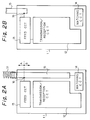
- FIGS. 2A and 2B A reference will be made to FIGS. 2A and 2B for describing a second embodiment of the present invention.
- the same or similar constituent parts as or to the parts of FIGS. 1A and 1B are designated by the same reference numerals, and a detailed description thereof will not be made in order to avoid redundancy.
- this embodiment is similar to the previous embodiment except that a conductor in the form of a coil 31 is connected to the antenna 15.
- the matching circuit 14 opens the impedance from the feed circuit 13 to the direction B of the antenna 15 with respect to the assigned frequency, as in the first embodiment.
- the matching section of the feed section 13 adjusts it to an adequate characteristic impedance, e.g., 50 ⁇ .
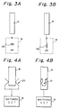
- FIGS. 3A and 3B each shows a specific configuration of the matching circuit 14 included in both of the first and second embodiments.
- the matching circuit 14 may be implemented by a capacitor 14a, as shown in FIG. 3A, or by an inductor 14b, as shown in FIG. 3B.
- FIGS. 4A and 4B each shows specific means for connecting the matching circuit 14 and antenna 15 also included in the embodiments.
- FIG. 4A shows connecting means 20 provided on the matching circuit 14.
- the connecting means 20 is so configured as to nip the lower end of the antenna 15 when the antenna 15 is retracted into the casing 11.
- FIG. 4B shows connecting means 21 which is provided on the lower end of the antenna 15.
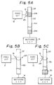
- FIGS. 5A-5C there will be described specific configurations of the antenna 15 and specific means for connecting the antenna 15 and feed circuit 13 at the feed point 16.
- FIG. 5A shows an antenna 15A which is implemented by a conductive rod and covered with an insulator except for a part thereof.
- the antenna 15A has insulated surface portions 22 and conductive surface portions 24a and 24b alternating with each other.
- Connecting means 26 is connected to the feed circuit 13 and constituted by, for example, a resilient contact member made of metal.
- the conductive surface portion 24a is brought into contact with the matching circuit 14.
- the other conductive portion 24b is connected to the contact member 26 at the feed point 16.
- FIG. 5B shows an antenna 15B whose surface is entirely covered with an insulator.
- connecting means 28 is implemented as a metallic member which does not contact the antenna 15B.
- FIG. 5C shows an antenna 15C which is essentially similar to the antenna 15B except that a conductive member 30 is carried on the lower or innermost end of the antenna 15C.
- the conductive member 30 is brought into contact with the metallic member 28.
- the present invention provides a portable radio communication apparatus which enhances, when an antenna thereof is held in a retracted position, the antenna gain and performs communication stably.
- This unprecedented advantage is derived from a unique matching circuit which is electrically connected to the antenna when the antenna is retracted into a casing.
Landscapes
- Engineering & Computer Science (AREA)
- Computer Networks & Wireless Communication (AREA)
- Signal Processing (AREA)
- Support Of Aerials (AREA)
- Details Of Aerials (AREA)
- Transceivers (AREA)
- Mobile Radio Communication Systems (AREA)
Applications Claiming Priority (3)
| Application Number | Priority Date | Filing Date | Title |
|---|---|---|---|
| JP64943/93 | 1993-03-24 | ||
| JP6494393 | 1993-03-24 | ||
| JP5064943A JP2570087B2 (ja) | 1993-03-24 | 1993-03-24 | 携帯型無線機 |
Publications (3)
| Publication Number | Publication Date |
|---|---|
| EP0617520A2 true EP0617520A2 (fr) | 1994-09-28 |
| EP0617520A3 EP0617520A3 (fr) | 1994-11-02 |
| EP0617520B1 EP0617520B1 (fr) | 2001-08-01 |
Family
ID=13272632
Family Applications (1)
| Application Number | Title | Priority Date | Filing Date |
|---|---|---|---|
| EP94104631A Expired - Lifetime EP0617520B1 (fr) | 1993-03-24 | 1994-03-23 | Appareil de radiocommunication portatif |
Country Status (6)
| Country | Link |
|---|---|
| US (1) | US5940745A (fr) |
| EP (1) | EP0617520B1 (fr) |
| JP (1) | JP2570087B2 (fr) |
| KR (1) | KR940023058A (fr) |
| AU (1) | AU677628B2 (fr) |
| DE (1) | DE69427838T2 (fr) |
Cited By (10)
| Publication number | Priority date | Publication date | Assignee | Title |
|---|---|---|---|---|
| WO1996021254A1 (fr) * | 1995-01-05 | 1996-07-11 | Paul Francis Bickert | Antenne perfectionnee pour dispositif de communication radio portable |
| EP0722195A1 (fr) * | 1995-01-12 | 1996-07-17 | Nec Corporation | Appareil radio portatif |
| EP0764998A1 (fr) * | 1995-09-22 | 1997-03-26 | Mitsubishi Denki Kabushiki Kaisha | Antenne |
| FR2742948A1 (fr) * | 1995-12-22 | 1997-06-27 | Motorola Inc | Dispositif de communication sans fil ayant un circuit d'adaptation reconfigurable |
| EP0795921A3 (fr) * | 1996-03-12 | 1997-09-24 | Siemens Aktiengesellschaft | Radio téléphone |
| GB2328082A (en) * | 1997-08-09 | 1999-02-10 | Samsung Electronics Co Ltd | Antenna matching circuit for cordless telephone |
| US5907307A (en) * | 1995-01-05 | 1999-05-25 | Bickert; Paul F. | Antenna for a portable radio communication device |
| US6064341A (en) * | 1998-05-14 | 2000-05-16 | Motorola, Inc. | Antenna assembly |
| EP1542313A1 (fr) * | 2003-12-11 | 2005-06-15 | Nec Corporation | Dispositif d'antenne comportant un circuit d'adaption d'impédance variable et appareil de radiocommunication portatif utilisant cette antenne |
| US7170454B2 (en) | 2005-03-30 | 2007-01-30 | Nokia Corporation | Antenna arrangement |
Families Citing this family (4)
| Publication number | Priority date | Publication date | Assignee | Title |
|---|---|---|---|---|
| US6243592B1 (en) | 1997-10-23 | 2001-06-05 | Kyocera Corporation | Portable radio |
| JP3611754B2 (ja) * | 1999-08-24 | 2005-01-19 | 株式会社ヨコオ | アンテナ構造 |
| JP3830773B2 (ja) * | 2001-05-08 | 2006-10-11 | 三菱電機株式会社 | 携帯電話機 |
| US20050245228A1 (en) * | 2004-04-29 | 2005-11-03 | Alejandro Candal | Portable communication device for supporting multiple communication modes over a common changeable antenna structure |
Family Cites Families (14)
| Publication number | Priority date | Publication date | Assignee | Title |
|---|---|---|---|---|
| JPS61168732U (fr) * | 1985-04-08 | 1986-10-20 | ||
| JPS63173934U (fr) * | 1987-04-30 | 1988-11-11 | ||
| JPH01160101A (ja) * | 1987-12-16 | 1989-06-23 | Matsushita Electric Ind Co Ltd | 空中線装置 |
| JPH01105237U (fr) * | 1987-12-28 | 1989-07-14 | ||
| US5144324A (en) * | 1989-08-02 | 1992-09-01 | At&T Bell Laboratories | Antenna arrangement for a portable transceiver |
| JP2554762B2 (ja) * | 1990-02-23 | 1996-11-13 | 株式会社東芝 | アンテナと無線機 |
| US5204687A (en) * | 1990-07-19 | 1993-04-20 | Galtronics Ltd. | Electrical device and electrical transmitter-receiver particularly useful in a ct2 cordless telephone |
| GB9105586D0 (en) * | 1991-03-16 | 1991-05-01 | Antenna Products Ltd | Radio antennas |
| JPH04132713U (ja) * | 1991-05-31 | 1992-12-09 | ソニー株式会社 | 携帯電話機 |
| JP3159395B2 (ja) * | 1991-07-12 | 2001-04-23 | 日本電信電話株式会社 | 携帯無線機 |
| DE69215283T2 (de) * | 1991-07-08 | 1997-03-20 | Nippon Telegraph & Telephone | Ausfahrbares Antennensystem |
| GB2257835B (en) * | 1991-07-13 | 1995-10-11 | Technophone Ltd | Retractable antenna |
| JP2702642B2 (ja) * | 1992-05-14 | 1998-01-21 | シャープ株式会社 | コードレス電話機用子機 |
| US5467096A (en) * | 1993-02-25 | 1995-11-14 | Nec Corporation | Antenna for a radio communication apparatus |
-
1993
- 1993-03-24 JP JP5064943A patent/JP2570087B2/ja not_active Expired - Fee Related
-
1994
- 1994-03-21 US US08/216,025 patent/US5940745A/en not_active Expired - Fee Related
- 1994-03-23 AU AU59025/94A patent/AU677628B2/en not_active Ceased
- 1994-03-23 EP EP94104631A patent/EP0617520B1/fr not_active Expired - Lifetime
- 1994-03-23 KR KR1019940005831A patent/KR940023058A/ko not_active Ceased
- 1994-03-23 DE DE69427838T patent/DE69427838T2/de not_active Expired - Fee Related
Cited By (22)
| Publication number | Priority date | Publication date | Assignee | Title |
|---|---|---|---|---|
| US5907307A (en) * | 1995-01-05 | 1999-05-25 | Bickert; Paul F. | Antenna for a portable radio communication device |
| WO1996021254A1 (fr) * | 1995-01-05 | 1996-07-11 | Paul Francis Bickert | Antenne perfectionnee pour dispositif de communication radio portable |
| AU709954B2 (en) * | 1995-01-05 | 1999-09-09 | Paul Francis Bickert | An antenna for a portable radio communication device |
| EP0722195A1 (fr) * | 1995-01-12 | 1996-07-17 | Nec Corporation | Appareil radio portatif |
| CN1070323C (zh) * | 1995-01-12 | 2001-08-29 | 日本电气株式会社 | 便携式射频设备 |
| US5794158A (en) * | 1995-01-12 | 1998-08-11 | Nec Corporation | Portable radio apparatus |
| EP0764998A1 (fr) * | 1995-09-22 | 1997-03-26 | Mitsubishi Denki Kabushiki Kaisha | Antenne |
| EP1075039A3 (fr) * | 1995-09-22 | 2003-04-16 | Mitsubishi Denki Kabushiki Kaisha | Dispositif d'antenne |
| US5949377A (en) * | 1995-09-22 | 1999-09-07 | Mitsubishi Denki Kabushiki Kaisha | Retractable, extendable and rotatable dual antenna system |
| DE19653180A1 (de) * | 1995-12-22 | 1997-07-24 | Motorola Inc | Drahtlose Kommunikationsvorrichtung mit einer rekonfigurierbaren Anpassschaltung |
| GB2308744B (en) * | 1995-12-22 | 1999-08-11 | Motorola Inc | Wireless communication device having a reconfigure matching circuit |
| US5754141A (en) * | 1995-12-22 | 1998-05-19 | Motorola, Inc. | Wireless communication device having a reconfigurable matching circuit |
| DE19653180C2 (de) * | 1995-12-22 | 1999-10-14 | Motorola Inc | Funksendeempfänger mit einer Anpaßschaltung |
| AU713057B2 (en) * | 1995-12-22 | 1999-11-25 | Motorola, Inc. | Wireless communication device having a reconfigurable matching circuit |
| GB2308744A (en) * | 1995-12-22 | 1997-07-02 | Motorola Inc | Wireless communication device has impedance matching for both antenna positions |
| FR2742948A1 (fr) * | 1995-12-22 | 1997-06-27 | Motorola Inc | Dispositif de communication sans fil ayant un circuit d'adaptation reconfigurable |
| EP0795921A3 (fr) * | 1996-03-12 | 1997-09-24 | Siemens Aktiengesellschaft | Radio téléphone |
| GB2328082A (en) * | 1997-08-09 | 1999-02-10 | Samsung Electronics Co Ltd | Antenna matching circuit for cordless telephone |
| US6064341A (en) * | 1998-05-14 | 2000-05-16 | Motorola, Inc. | Antenna assembly |
| EP1542313A1 (fr) * | 2003-12-11 | 2005-06-15 | Nec Corporation | Dispositif d'antenne comportant un circuit d'adaption d'impédance variable et appareil de radiocommunication portatif utilisant cette antenne |
| US7176841B2 (en) | 2003-12-11 | 2007-02-13 | Nec Corporation | Antenna device and radio communication apparatus using the antenna device |
| US7170454B2 (en) | 2005-03-30 | 2007-01-30 | Nokia Corporation | Antenna arrangement |
Also Published As
| Publication number | Publication date |
|---|---|
| US5940745A (en) | 1999-08-17 |
| AU677628B2 (en) | 1997-05-01 |
| DE69427838D1 (de) | 2001-09-06 |
| EP0617520A3 (fr) | 1994-11-02 |
| EP0617520B1 (fr) | 2001-08-01 |
| DE69427838T2 (de) | 2002-04-11 |
| JP2570087B2 (ja) | 1997-01-08 |
| JPH06276117A (ja) | 1994-09-30 |
| KR940023058A (ko) | 1994-10-22 |
| AU5902594A (en) | 1994-09-29 |
Similar Documents
| Publication | Publication Date | Title |
|---|---|---|
| US5940745A (en) | Portable transceiver having retractable antenna and matching circuit | |
| EP0367609B1 (fr) | Antenne pliante pour des radiotéléphones portatives dans un système cellulaire | |
| JP2554762B2 (ja) | アンテナと無線機 | |
| JP2703670B2 (ja) | アンテナ装置 | |
| JP3202690B2 (ja) | 携帯無線機用アンテナ | |
| EP0582423B1 (fr) | Antenne pour appareil radio | |
| EP0997967B1 (fr) | Unité d'antenne rétractable pour un téléphone portable | |
| EP0718909A2 (fr) | Antenne rétractable à charge en sommet | |
| US6097341A (en) | Structure of an antenna for a portable radio communication apparatus | |
| US6239768B1 (en) | Dual band retractable antenna system with capacitive coupling | |
| JP3515559B2 (ja) | 多周波用アンテナ | |
| EP0980113A2 (fr) | Antenne | |
| US6008765A (en) | Retractable top load antenna | |
| JP3244300B2 (ja) | 無線電話装置 | |
| EP0736925A2 (fr) | Une antenne à double action et un téléphone mobile avec une telle antenne | |
| US5918162A (en) | Antenna unit and portable radio terminal with a feeding circuit and spiral antenna | |
| JP2579095B2 (ja) | 移動通信機用アンテナ装置 | |
| JPH11163757A (ja) | アンテナ及びアンテナ回路 | |
| JP3134720B2 (ja) | 携帯電話機のアンテナ装置 | |
| US7167131B2 (en) | Antenna | |
| JPH066121A (ja) | アンテナ装置 | |
| JP2501413B2 (ja) | アンテナと無線機 | |
| JP3770423B2 (ja) | アンテナ装置及び携帯無線機 | |
| JP2000353907A (ja) | 複合アンテナ | |
| US20030080896A1 (en) | Portable communication device antenna |
Legal Events
| Date | Code | Title | Description |
|---|---|---|---|
| PUAI | Public reference made under article 153(3) epc to a published international application that has entered the european phase |
Free format text: ORIGINAL CODE: 0009012 |
|
| PUAL | Search report despatched |
Free format text: ORIGINAL CODE: 0009013 |
|
| AK | Designated contracting states |
Kind code of ref document: A2 Designated state(s): DE FR GB IT NL SE |
|
| AK | Designated contracting states |
Kind code of ref document: A3 Designated state(s): DE FR GB IT NL SE |
|
| 17P | Request for examination filed |
Effective date: 19940915 |
|
| 17Q | First examination report despatched |
Effective date: 19980202 |
|
| GRAG | Despatch of communication of intention to grant |
Free format text: ORIGINAL CODE: EPIDOS AGRA |
|
| GRAG | Despatch of communication of intention to grant |
Free format text: ORIGINAL CODE: EPIDOS AGRA |
|
| GRAH | Despatch of communication of intention to grant a patent |
Free format text: ORIGINAL CODE: EPIDOS IGRA |
|
| GRAH | Despatch of communication of intention to grant a patent |
Free format text: ORIGINAL CODE: EPIDOS IGRA |
|
| GRAA | (expected) grant |
Free format text: ORIGINAL CODE: 0009210 |
|
| AK | Designated contracting states |
Kind code of ref document: B1 Designated state(s): DE FR GB IT NL SE |
|
| REF | Corresponds to: |
Ref document number: 69427838 Country of ref document: DE Date of ref document: 20010906 |
|
| ET | Fr: translation filed | ||
| REG | Reference to a national code |
Ref country code: GB Ref legal event code: IF02 |
|
| PG25 | Lapsed in a contracting state [announced via postgrant information from national office to epo] |
Ref country code: SE Free format text: LAPSE BECAUSE OF NON-PAYMENT OF DUE FEES Effective date: 20020324 |
|
| PLBE | No opposition filed within time limit |
Free format text: ORIGINAL CODE: 0009261 |
|
| STAA | Information on the status of an ep patent application or granted ep patent |
Free format text: STATUS: NO OPPOSITION FILED WITHIN TIME LIMIT |
|
| 26N | No opposition filed | ||
| PG25 | Lapsed in a contracting state [announced via postgrant information from national office to epo] |
Ref country code: NL Free format text: LAPSE BECAUSE OF NON-PAYMENT OF DUE FEES Effective date: 20021001 |
|
| EUG | Se: european patent has lapsed |
Ref document number: 94104631.0 |
|
| NLV4 | Nl: lapsed or anulled due to non-payment of the annual fee |
Effective date: 20021001 |
|
| PGFP | Annual fee paid to national office [announced via postgrant information from national office to epo] |
Ref country code: GB Payment date: 20090318 Year of fee payment: 16 |
|
| PGFP | Annual fee paid to national office [announced via postgrant information from national office to epo] |
Ref country code: IT Payment date: 20090319 Year of fee payment: 16 Ref country code: DE Payment date: 20090319 Year of fee payment: 16 |
|
| PGFP | Annual fee paid to national office [announced via postgrant information from national office to epo] |
Ref country code: FR Payment date: 20090316 Year of fee payment: 16 |
|
| GBPC | Gb: european patent ceased through non-payment of renewal fee |
Effective date: 20100323 |
|
| REG | Reference to a national code |
Ref country code: FR Ref legal event code: ST Effective date: 20101130 |
|
| PG25 | Lapsed in a contracting state [announced via postgrant information from national office to epo] |
Ref country code: FR Free format text: LAPSE BECAUSE OF NON-PAYMENT OF DUE FEES Effective date: 20100331 |
|
| PG25 | Lapsed in a contracting state [announced via postgrant information from national office to epo] |
Ref country code: DE Free format text: LAPSE BECAUSE OF NON-PAYMENT OF DUE FEES Effective date: 20101001 |
|
| PG25 | Lapsed in a contracting state [announced via postgrant information from national office to epo] |
Ref country code: GB Free format text: LAPSE BECAUSE OF NON-PAYMENT OF DUE FEES Effective date: 20100323 Ref country code: IT Free format text: LAPSE BECAUSE OF NON-PAYMENT OF DUE FEES Effective date: 20100323 |