EP0617542A2 - Aufzeichnungs- und/oder Wiedergabegerät - Google Patents
Aufzeichnungs- und/oder Wiedergabegerät Download PDFInfo
- Publication number
- EP0617542A2 EP0617542A2 EP94104440A EP94104440A EP0617542A2 EP 0617542 A2 EP0617542 A2 EP 0617542A2 EP 94104440 A EP94104440 A EP 94104440A EP 94104440 A EP94104440 A EP 94104440A EP 0617542 A2 EP0617542 A2 EP 0617542A2
- Authority
- EP
- European Patent Office
- Prior art keywords
- signal processing
- image
- data
- recording
- signal
- Prior art date
- Legal status (The legal status is an assumption and is not a legal conclusion. Google has not performed a legal analysis and makes no representation as to the accuracy of the status listed.)
- Granted
Links
Images


Classifications
-
- H—ELECTRICITY
- H04—ELECTRIC COMMUNICATION TECHNIQUE
- H04N—PICTORIAL COMMUNICATION, e.g. TELEVISION
- H04N1/00—Scanning, transmission or reproduction of documents or the like, e.g. facsimile transmission; Details thereof
- H04N1/00127—Connection or combination of a still picture apparatus with another apparatus, e.g. for storage, processing or transmission of still picture signals or of information associated with a still picture
- H04N1/00204—Connection or combination of a still picture apparatus with another apparatus, e.g. for storage, processing or transmission of still picture signals or of information associated with a still picture with a digital computer or a digital computer system, e.g. an internet server
- H04N1/00236—Connection or combination of a still picture apparatus with another apparatus, e.g. for storage, processing or transmission of still picture signals or of information associated with a still picture with a digital computer or a digital computer system, e.g. an internet server using an image reading or reproducing device, e.g. a facsimile reader or printer, as a local input to or local output from a computer
- H04N1/00241—Connection or combination of a still picture apparatus with another apparatus, e.g. for storage, processing or transmission of still picture signals or of information associated with a still picture with a digital computer or a digital computer system, e.g. an internet server using an image reading or reproducing device, e.g. a facsimile reader or printer, as a local input to or local output from a computer using an image reading device as a local input to a computer
-
- H—ELECTRICITY
- H04—ELECTRIC COMMUNICATION TECHNIQUE
- H04N—PICTORIAL COMMUNICATION, e.g. TELEVISION
- H04N1/00—Scanning, transmission or reproduction of documents or the like, e.g. facsimile transmission; Details thereof
- H04N1/00127—Connection or combination of a still picture apparatus with another apparatus, e.g. for storage, processing or transmission of still picture signals or of information associated with a still picture
- H04N1/00204—Connection or combination of a still picture apparatus with another apparatus, e.g. for storage, processing or transmission of still picture signals or of information associated with a still picture with a digital computer or a digital computer system, e.g. an internet server
- H04N1/00236—Connection or combination of a still picture apparatus with another apparatus, e.g. for storage, processing or transmission of still picture signals or of information associated with a still picture with a digital computer or a digital computer system, e.g. an internet server using an image reading or reproducing device, e.g. a facsimile reader or printer, as a local input to or local output from a computer
-
- H—ELECTRICITY
- H04—ELECTRIC COMMUNICATION TECHNIQUE
- H04N—PICTORIAL COMMUNICATION, e.g. TELEVISION
- H04N1/00—Scanning, transmission or reproduction of documents or the like, e.g. facsimile transmission; Details thereof
- H04N1/21—Intermediate information storage
- H04N1/2104—Intermediate information storage for one or a few pictures
- H04N1/2112—Intermediate information storage for one or a few pictures using still video cameras
-
- H—ELECTRICITY
- H04—ELECTRIC COMMUNICATION TECHNIQUE
- H04N—PICTORIAL COMMUNICATION, e.g. TELEVISION
- H04N1/00—Scanning, transmission or reproduction of documents or the like, e.g. facsimile transmission; Details thereof
- H04N1/21—Intermediate information storage
- H04N1/2104—Intermediate information storage for one or a few pictures
- H04N1/2158—Intermediate information storage for one or a few pictures using a detachable storage unit
-
- H—ELECTRICITY
- H04—ELECTRIC COMMUNICATION TECHNIQUE
- H04N—PICTORIAL COMMUNICATION, e.g. TELEVISION
- H04N23/00—Cameras or camera modules comprising electronic image sensors; Control thereof
- H04N23/60—Control of cameras or camera modules
- H04N23/617—Upgrading or updating of programs or applications for camera control
-
- H—ELECTRICITY
- H04—ELECTRIC COMMUNICATION TECHNIQUE
- H04N—PICTORIAL COMMUNICATION, e.g. TELEVISION
- H04N5/00—Details of television systems
- H04N5/76—Television signal recording
- H04N5/765—Interface circuits between an apparatus for recording and another apparatus
- H04N5/77—Interface circuits between an apparatus for recording and another apparatus between a recording apparatus and a television camera
- H04N5/772—Interface circuits between an apparatus for recording and another apparatus between a recording apparatus and a television camera the recording apparatus and the television camera being placed in the same enclosure
-
- H—ELECTRICITY
- H04—ELECTRIC COMMUNICATION TECHNIQUE
- H04N—PICTORIAL COMMUNICATION, e.g. TELEVISION
- H04N5/00—Details of television systems
- H04N5/76—Television signal recording
- H04N5/91—Television signal processing therefor
- H04N5/92—Transformation of the television signal for recording, e.g. modulation, frequency changing; Inverse transformation for playback
- H04N5/926—Transformation of the television signal for recording, e.g. modulation, frequency changing; Inverse transformation for playback by pulse code modulation
- H04N5/9261—Transformation of the television signal for recording, e.g. modulation, frequency changing; Inverse transformation for playback by pulse code modulation involving data reduction
-
- H—ELECTRICITY
- H04—ELECTRIC COMMUNICATION TECHNIQUE
- H04N—PICTORIAL COMMUNICATION, e.g. TELEVISION
- H04N2101/00—Still video cameras
-
- H—ELECTRICITY
- H04—ELECTRIC COMMUNICATION TECHNIQUE
- H04N—PICTORIAL COMMUNICATION, e.g. TELEVISION
- H04N2201/00—Indexing scheme relating to scanning, transmission or reproduction of documents or the like, and to details thereof
- H04N2201/0008—Connection or combination of a still picture apparatus with another apparatus
- H04N2201/0034—Details of the connection, e.g. connector, interface
-
- H—ELECTRICITY
- H04—ELECTRIC COMMUNICATION TECHNIQUE
- H04N—PICTORIAL COMMUNICATION, e.g. TELEVISION
- H04N2201/00—Indexing scheme relating to scanning, transmission or reproduction of documents or the like, and to details thereof
- H04N2201/0077—Types of the still picture apparatus
-
- H—ELECTRICITY
- H04—ELECTRIC COMMUNICATION TECHNIQUE
- H04N—PICTORIAL COMMUNICATION, e.g. TELEVISION
- H04N5/00—Details of television systems
- H04N5/76—Television signal recording
- H04N5/78—Television signal recording using magnetic recording
- H04N5/781—Television signal recording using magnetic recording on disks or drums
Definitions
- This invention relates to a recording and/or reproducing apparatus arranged to process, record and/or reproduce images and sounds.
- Fig. 8 shows in a block diagram a conventional digital electronic camera.
- the digital electronic camera 800 is arranged to use a memory card 801 as a recording medium.
- the camera 800 includes a photo-taking lens 1, a diaphragm shutter 2 which is a shutter, but functions as a diaphragm as well, and a flash device 3.
- a CPU 4 is arranged to control mechanical and operation parts.
- a driving circuit 5 is arranged to drive each part of a mechanical system.
- An image sensor 6 is arranged to convert into an electrical signal a reflection light which comes from an object of shooting.
- a timing signal generating circuit (abbreviated to a TG circuit) 7 is arranged to generate a timing signal necessary for operating the image sensor 6.
- An image sensor driving circuit 8 is arranged to amplify the timing signal from the timing signal generating circuit 7 up to a level necessary for driving the image sensor 6.
- a preprocessing circuit 9 is provided with a CDS circuit for removing a noise from the output of the image sensor 6 and a nonlinear type amplifying circuit for amplifying the output of the image sensor 6 prior to an A/D (analog-to-digital) conversion process.
- Reference numeral 10 denotes an A/D converter and reference numeral 12 a buffer memory.
- a signal processing system control CPU 13 is arranged to control each part of a signal processing system.
- An operation display part 14 is arranged to make a display in aid of operation by showing the state of the camera.
- An operation part 15 is provided for operating the camera from outside.
- a memory controller 802 is arranged to control the buffer memory 12.
- a digital signal processing circuit 803 is arranged to make the output of the image sensor 6 into a form suited for recording on the memory card 801.
- a memory card interface (I/F) 804 is arranged to connect the digital electronic camera 800 to the memory card 801.
- the conventional digital electronic camera 800 operates as described below with reference to Fig. 8:
- the digital electronic camera 800 enters into a state of performing a shooting action.
- the photo-taking lens 1 is controlled by the mechanical and operation part control CPU 4 and the mechanical system driving circuit 5 in accordance with the intention of the operator.
- the conditions of shooting, etc. are displayed at the operation part 15 to inform the operator of the state of the camera 800.
- the luminance of the object of shooting is measured by a light measuring circuit which is not shown.
- An aperture value and a shutter speed of the diaphragm shutter 2 are then derived from the mechanical and operation part control CPU 4.
- the mechanical system driving circuit 5 drives the diaphragm shutter 2 on the basis of the control values thus derived from the CPU 4.
- a shot may be taken by flashing the flash device 3.
- a reflection light from the object of shooting comes to fall upon the image sensor 6 via the photo-taking lens 1 and the diaphragm shutter 2.
- the diaphragm shutter 2 then acts to limit the quantity of the incident light upon the image sensor 6.
- the image sensor 6 is an interlaced reading type CCD, the diaphragm shutter 2 is arranged to prevent an electric charge signal from being affected by the incident light.
- the image sensor 6 is arranged to be operated by a driving signal which is outputted from the TG circuit 7 and is amplified by the image sensor driving circuit 8.
- the action of the TG circuit 7 is controlled by the signal processing system control CPU 13.
- the output of the image sensor 6 which is driven in this manner is supplied to the preprocessing circuit 9.
- the preprocessing circuit 9 Upon receipt of the output of the image sensor 6, the preprocessing circuit 9 performs a CDS (correlated double sampling) process to remove a low band noise from the output of the image sensor 6 (or a pickup image signal) and a process of making the pickup image signal into a nonlinear state for the effective use of the dynamic range of the A/D converter 10.
- the pickup image signal thus preprocessed is converted into a digital signal by the A/D converter 10.
- the digital signal thus obtained is inputted to the memory controller 802.
- the memory controller 802 Under the control of the signal processing system control CPU 13, the memory controller 802 at first temporarily stores the digitized pickup image signal in the buffer memory 12 and then reads out the stored digital signal in order as determined by the arrangement of color filters of the image sensor 6. The digital signal thus read out is converted into a signal of a predetermined format by the digital signal processing circuit 803. The signal thus processed is recorded on the memory card 801 through the memory card interface (I/F) 804.
- I/F memory card interface
- This invention is directed to the solution of the problems mentioned above. It is an object of this invention to provide a recording and/or reproducing apparatus which comprises an optical system arranged to form an optical image, photo-electric conversion means for converting the optical image formed by the optical system into an electrical signal, A/D conversion means for converting the electrical signal and/or an audio signal into a digital signal, a connector arranged to permit mounting and demounting a recording medium on which the digital signal obtained from the A/D conversion means is to be recorded, and signal processing means for processing and converting the digital signal, the signal processing means being arranged to be mountable and demountable on and from the recording and/or reproducing apparatus.
- the apparatus arranged in accordance with this invention as an embodiment thereof is arranged to permit mounting and demounting not only the recording medium but also a part of a digital electronic camera having some specific function, such as a signal processing part, so that the size and the price of the digital electronic camera which is a basic part of the recording and/or reproducing apparatus can be minimized and the functions and the performance of the apparatus having the camera as its basic part can be altered as desired.
- a digital electronic camera is provided with an interface for a recording medium, a signal processing and compressing part and an extended card interface having an external interface.
- the digital electronic camera according to this invention performs a minimum range of functions as a digital electronic camera when the extended card is not mounted on the camera. With the extended card mounted, however, the image and sound signal processing capability of the digital electronic camera is greatly enhanced and also the camera gains access to an external interface, so that a highly advanced system can be formed.
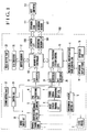
- Fig. 1 shows in a block diagram the arrangement of a system consisting of the digital electronic camera body and the extended card.
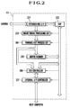
- Fig. 2 shows in a block diagram the arrangement of the extended card.
- Fig. 1 shows in a block diagram the arrangement of a system consisting of the digital electronic camera body and the extended card.
- Fig. 2 shows in a block diagram the arrangement of the extended card.
- all elements that function in the same manner as those of the conventional apparatus which is shown in Fig. 8 and described in the foregoing are indicated by the same reference numerals as in Fig. 8.
- a recording medium 101 is a memory card or a hard disk which conforms with the specifications of PCMCIA (Personal Computer Memory Card International Association), or the like.
- the camera body 100 includes a sound input circuit 20 and a sound output part 22 which is either a speaker or an audio jack.
- An A/D (analog-to-digital) converter 24 is provided for an audio signal and a D/A (digital-to-analog) converter 25 for the audio signal.
- a switch circuit 21 is provided for the audio signal to be supplied to the sound output part 22.
- a memory bus controller 102 is provided for transfer of image and sound data between a signal processing system control CPU 13 and an extended card 111 of the PCMCIA Standards or a recording medium 101 and also for transfer of image data to a buffer memory 12 for an image display.
- a D/A converter 26 is arranged to convert the image data of the image display buffer memory 12 into an analog video signal.
- a video output part 23 is provided for displaying the analog video signal.
- An extended bus interface (I/F) 110 is arranged between the extended card 111 and the camera body 100.
- a controller 201 is provided for the transfer of digital data on the extended card interface.
- a digital signal processor (DSP) 202 (hereinafter referred to as signal processing DSP) is arranged to communicate with a host computer 112 through a compressing/expanding process and an external interface.
- a pickup image signal processing circuit 203 is arranged to perform a pickup image signal processing action on unprocessed image data.
- a thinning-out process circuit 204 is provided for thinning out the signal processed by the pickup image signal processing circuit 203 in the vertical and horizontal spatial directions and for reducing the number of images per unit time.
- a buffer memory 205 is arranged to temporarily hold uncompressed image data.
- a bus controller 206 is arranged to control transfer of data between the thinning-out process circuit 204, the signal processing DSP 202 and an external interface (I/F) controller 207.
- the external I/F controller 207 is, for example, an SCSI controller which controls communication with an external interface.
- the extended bus interfaces 110 and 201 will be hereinafter called the extended bus interface.
- the signal processing system control CPU 13 performs control over the whole camera, filing and a display of image data and filing and reproduction of sound data. The details of the manner in which these functions are actually carried out are described as follows: (1-1) Monitoring of images to be recorded in an image recording mode: When an instruction given by the operator for a shift to the recording mode through the operation part 15 is detected by the mechanical and operation part control CPU 4, the signal processing system control CPU 13 makes a display of a recording image through the following process:
- the signal processing system control CPU 13 sets the memory bus controller 102 into a mode of writing the data outputted from the A/D converter 10 into the image display buffer memory 12.
- Image data which has not been subjected to the pickup image signal processing action is converted into digital data by the A/D converter 10 and is then written into the image display buffer memory 12 by the memory bus controller 102.
- the digital data thus written in the image display buffer memory 12 is converted into an analog video signal by the D/A converter 26.
- the analog video signal is sent to the video output part 23 to be displayed there in a state which enables the operator to visually confirm the recording image as a motion image.
- the image display buffer memory 12 which is provided only for a simple display of images does not have many picture elements and displays no color information.
- the memory bus controller 102 is arranged either to extract some picture element data which corresponds to one color, green for example, to use it as a luminance image or to compute and obtain a luminance image from information on a plurality of colors by a simple filter computing operation.
- a motion image obtained from the image sensor 6 through the above-stated process is displayed at the video output part 23.
- the image being recorded can be held still at the video output part 23 if the memory bus controller 102 gives pause to writing into the image display buffer memory 12, so that a still image currently recorded can be confirmed at the video output part 23 by the operator during that period.
- the signal processing system control CPU 13 receives the sound data converted into digital data by the A/D converter 24 and transfers the digital sound data to the recording medium interface 104 through the memory bus controller 102.
- the recording file format may be of a file structure such as that of the MS-DOS.
- the signal processing system control CPU 13 holds sound data received from the A/D converter 24 within an internal buffer of the signal processing system control CPU 13 for a period of time during which the images are transferred to the recording medium interface 104. When the image transfer period expires, the sound data is transferred to the recording medium interface 104.
- One field period of the NTSC system which is 16.7 msec, includes a period of about 1.4 msec called a vertical blanking period, during which no video signal appears beginning before and ending after a vertical synchronizing period.
- the image data which has not been subjected to the pickup image signal processing action is transferred during a period of about 15 msec excluding this vertical blanking period.
- the data is transferred at a speed rate of about 10 Mbyte/sec.
- the data capacity for 16.7 msec is about 370 bytes.
- the transfer In a case where the data is to be transferred in remaining 1.4 msec, the transfer must be made at a speed of about 260 Kbyte/sec.
- the recording medium for example, a memory card which conforms to the specifications of the PCMCIA or the like.
- the sound data is transferred during the vertical blanking period and the image data during the video period within the period of one picture in a time-division mutliplexing manner. Recording thus can be accomplished while simultaneously monitoring both the images and the sounds.
- the sound data can be regarded as information related to the images, the images and the sounds can be filed and managed in pairs.
- the sound data may be transferred within a horizontal blanking period of the video signal instead of the vertical blanking period.
- the sound is sampled at 44.1 KHz, stereophonic and 8 bits
- the sound data of a total of 6 bytes or 4 bytes is transfered and recorded within one horizontal blanking period.
- the recording is preferably performed in such a way as to interleave the sound data for every horizontal scanning period.
- interleave recording may be performed for every vertical scanning period in such a way as to have the sound data recorded before the image data of one vertical scanning period.
- the sound data can be reproduced by the process of a next function described in the following paragraph, or function, (1-6): (1-6) Reproduction of sounds:
- the signal processing system control CPU 13 controls the switch circuit 21 to have the output of the D/A converter 25 connected to the input of the sound output part 22.
- the signal processing system control CPU 13 controls the recording medium interface 104 and the memory bus controller 102 to read out the sound data from the recording medium 101.
- the sound data is outputted to the D/A converter 25 at the same sampling frequency as the sampling frequency of recording.
- the sound output part 22 then outputs the sounds.
- the extended card functions to perform a pickup image signal processing action and compressing and expanding processes on images and to perform compressing and expanding processes on sounds.
- the extended card also allows the camera to have access to an external interface as well as to the recording medium interface 104.
- the pickup image signal processing action and the compressing and expanding processes can be carried out on the signal obtained from the image sensor 6.
- the form of data on the recording medium thus can be changed.
- the data on the recording medium can be transferred to an external interface after the form of the data is converted into another form as necessary. Data from an external interface can be received and its form can be changed before recording it on the recording medium or returning it to the external interface.
- the image data is processed by the pickup image signal processing circuit 203 to be converted into luminance information and color information.
- the output of the pickup image signal processing circuit 203 is either thinned out or not thinned out by the thinning-out process circuit 204 according to the recording mode.
- the information is then transferred to the buffer memory 205.
- the thinning-out process circuit 204 informs the signal processing DSP 202 of the completion of the transfer of the image data.
- the signal processing DSP 202 Upon receipt of the notice of completion of image data transfer, the signal processing DSP 202 compresses the data on the buffer memory 205 and controls the extended bus interface, the memory bus controller 102 and the recording medium interface 104 to have the data recorded on the recording medium 101.
- the signal processing DSP 202 is capable of adding a thinned-out image of the compressed image to the file of compressed data.
- the image assumed to be thinned down to 1/8 or thereabout of its original state longitudinally and transversely for example, the addition of the thinned-down image does not cause any excessive increase in the file capacity.
- An image obtained in this manner is called an index image.
- the signal processing DSP 202 receives the data from the extended bus interface and compresses it.
- the compressed data is recorded on the recording medium 101 through the extended bus interface, the memory bus controller 102 and the recording medium interface 104. This action is performed during one sampling period of the sound data.
- the signal processing system control CPU 13 When the mechanical and operation part control CPU 4 detects an instruction given by the operator through the operation part 15 to cancel the sound recording instruction, the signal processing system control CPU 13 notifies the signal processing DSP 202 of termination of the sound recording.
- This arrangement may be changed to cause the signal processing DSP 202 to terminate the sound recording by considering the sound recording instruction to be canceled when a predetermined period of time lapses and to notify the signal processing system control CPU 13 of the termination of the sound recording.
- the conversion of unprocessed image data into uncompressed image data and the transfer of it to the buffer memory 205 are carried out in the same manner as in the function (2-1) described above. In this case, however, the signal processing DSP 202 does not begin to perform image compressing and recording actions until it is notified of termination of sound recording from the signal processing system control CPU 13.
- the signal processing system control CPU 13 controls the memory bus controller 102 in such a manner that the image data is transferred to the extended bus interface, instead of transferring it to the recording medium interface, unlike the function (1-4) "simultaneous recording of images and sounds".
- the signal processing system control CPU 13 performs buffering and filing processes on the sound data by time-division multiplexing in synchronism with the image transfer by the memory bus controller 102 in the same manner as the function (1-4).
- the signal processing system control CPU 13 Upon completion of filing the uncompressed sound data, the signal processing system control CPU 13 notifies the signal processing DSP 202 of completion of the sound recording.
- the signal processing DSP 202 Upon receipt of the notice of completion of the sound recording from the signal processing system control CPU 13, the signal processing DSP 202 performs image compressing and recording actions in the same manner as in the case of the function (2-1). Further, the DSP 202 reads out the uncompressed sound data recorded by the signal processing system control CPU 13 by controlling the recording medium interface 104, the memory bus controller 102 and the extended bus interface and compresses it by transferring it to the buffer memory 205 to an amount allowable by the capacity thereof. After compression, the sound data is recorded on the recording medium 101 through the extended bus interface and the memory bus controller 102. This action is repeated until all the uncompressed sound data is compressed. Upon completion of compression, the signal processing system control CPU 13 erases the file of recorded uncompressed sound data from the recording medium 101.
- the signal processing DSP 202 controls the pickup image signal processing circuit 203 and the thinning-out process circuit 204 in such a way as to receive unprocessed image data from the extended bus interface.
- the signal processing DSP 202 controls the bus controller 206 to have the image data transferred from the thinning-out process circuit 204 to the external interface controller 207 and also sets a mode for the external interface controller 207 to receive data from the bus controller 206 and to transfer it to an external bus.
- Unprocessed image data is processed into luminance information and color information by the pickup image signal processing circuit 203.
- the output of the pickup image signal processing circuit 203 is thinned out as necessary by the thinning-out process circuit 204 and then is transferred to the external interface controller 207.
- the thinning-out process circuit 204 is arranged to notify the signal processing DSP 202 of completion of the transfer of the luminance and color information to the external interface controller 207 upon completion of the transfer for one picture.
- the signal processing DSP 202 then notifies the signal processing system control CPU 13 of completion of the transfer of the image data.
- the signal processing system control CPU 13 holds the sound data received from the A/D converter 24 in its internal buffer during the period of transfer of the image data to the external interface controller 207. This period is about 15 msec as mentioned in the foregoing with respect to the function (1-4).
- a buffer capacity for buffering is about 370 bytes.
- (2-4-2) Transfer of sound data Upon receipt of the notice of completion of image data transfer, the signal processing system control CPU 13 allows the sound data held in the internal buffer during the period of transfer of image data to be transferred to the signal processing DSP 202 through the memory bus controller 102 and the extended bus interface. During the period of the transfer of the sound data also, the signal processing system control CPU 13 holds the data received from the A/D converter 24 in the internal buffer thereof.
- the signal processing DSP 202 changes the bus controller 206 from one state over to another in such a way as to allow the sound data received from the signal processing system control CPU 13 to be transferred to the external interface controller 207.
- the function (2-4-1) is performed on the signal of a next video field.
- the functions (2-4-1) and (2-4-2) alternately repeated the image data and sound data are transferred in a state of being time-division multiplexed with each other.
- This action continues until some instruction for termination is received from the external interface.
- the instruction for termination may be obtained with an attention condition generated by the host computer 112.
- the speed of transfer to the external interface must be higher than the maximum speed of data generation.
- the insufficiency can be offset and covered by thinning out the data through the thinning-out process circuit 204.
- the image data is spatially thinned or the number of images is thinned (reduced) or both of these thinning methods may be employed.
- the signal processing system control CPU 13 must have a large buffer capacity for buffering the sound data. Therefore, this is a matter of trade-off.
- the image data is processed by the pickup image signal processing circuit 203 into luminance and color information.
- the output of the pickup image signal processing circuit 203 is thinned, if necessary according to the image size of the image display buffer memory 12, by the thinning-out process circuit 204 and is transferred to the buffer memory 205.
- the thinning-out process circuit 204 After completion of transfer of the luminance and color information to the buffer memory 205, the thinning-out process circuit 204 notifies the signal processing DSP 202 of completion of the transfer.
- the signal processing DSP 202 transfers the luminance information data of the buffer memory 205 to the image display buffer memory 12 by controlling the extended bus interface and the memory bus controller 102.
- the expanding process is not necessary.
- the image data is thinned or interpolated, or left as it is according to the image size of the image display buffer memory 12 and, after that, is transferred to the image display buffer memory 12 through the extended bus interface and the memory bus controller 102.
- the signal processing system control CPU 13 controls the switch circuit 21 to select the output of the D/A converter 25.
- the signal processing DSP 202 controls the recording medium interface 104, the memory bus controller 102 and the extended bus interface to read out the sound data. If the sound file consists of uncompressed sound data, the sound data read out is transferred as it is to the signal processing system control CPU 13. If the sound file consists of compressed sound data, the sound data is expanded before it is transferred to the signal processing system control CPU 13. The signal processing system control CPU 13 then outputs and supplies the sound data received to the D/A converter 25 at the same frequency as the sampling frequency employed at the time of recording.
- images transferable to the host computer 112 are assumed to be in the forms of unprocessed images, compressed images and uncompressed images.
- the signal processing DSP 202 reads out the image data from the recording medium 101 by controlling the recording medium interface 104, the memory bus controller 102 and the extended bus interface, and transfers the image data to the bus controller 206 and the external interface controller 207.
- the signal processing DSP 202 causes the pickup image signal processing circuit 203 to process the unprocessed image data into uncompressed image data and transfers it to the bus controller 206 and the external interface controller 207, in the same manner as in the case of the function (2-4-1) described in the foregoing.
- the signal processing DSP 202 causes the unprocessed image data to be processed into uncompressed image data by the pickup image signal processing circuit 203 and to be transferred to the buffer memory 205, in the same manner as the function (2-4-1).
- the signal processing DSP 202 then compresses the uncompressed image data and transfers the compressed image data to the bus controller 206 and the external interface controller 207.
- the signal processing DSP 202 expands the compressed image data and, after that, transfers it to the external interface controller 207, in the same manner as in the case of the function (2-4-2) described in the foregoing.
- the recording medium 101 is assumed to have an uncompressed or compressed sound file recorded thereon. Sounds are assumed to be transferred to the host computer 112 in the form of uncompressed or compressed sounds.
- the signal processing DSP 202 reads the sound data out from the recording medium 101 by controlling the recording medium interface 104, the memory bus controller 102 and the extended bus interface and transfers the sound data to the bus controller 206 and the external interface controller 207.
- the signal processing DSP 202 reads out the sound data by controlling the recording medium interface 104, the memory bus controller 102 and the extended bus interface. In converting uncompressed sound data into compressed sound data, the signal processing DSP 202 compresses the data and supplies it to the bus controller 206 and the external interface controller 207. In converting compressed sound data into uncompressed sound data, the signal processing DSP 202 expands the data and supplies it to the bus controller 206 and the external interface controller 207.
- the host computer 112 issues an instruction to the camera of this embodiment through the external interface and image data is transferred from the host computer 112 to the camera to have it recorded on the recording medium 101.
- the image data to be transferred from the host computer 112 is in the form of an unprocessed image, a compressed image or an uncompressed image.
- the image data is in the form of a compressed image.
- the signal processing DSP 202 receives the image data from the external interface controller 207 and records it on the recording medium 101 by controlling the extended bus interface, the memory bus controller 102 and the recording medium interface 104.
- the signal processing DSP 202 receives unprocessed image data from the external interface controller 207 and transfers the data to the image pickup signal processing circuit 203 to form uncompressed image data at the buffer memory 205. After that, the signal processing DSP 202 compresses the image data and records the compressed image data on the recording medium 101. In some other case, the signal processing DSP 202 receives uncompressed data and records it on the recording medium 101 by compressing it.
- the host computer 112 instructs the camera of this embodiment through the external interface to convert the form of the data transferred from the host computer and, after conversion, to return the data to the external interface.
- the forms of the image data to be transferred from the host computer 112 include an unprocessed image, a compressed image and an uncompressed image.
- the image data to be returned is in the form of a compressed image or an uncompressed image.
- the sound data to be transferred from and returned to the host computer 112 is in the form of compressed sounds or uncompressed sounds.
- the signal processing DSP 202 receives the unprocessed image data through the external interface controller 207 and the bus controller 206.
- the data thus received is transferred to the pickup image processing circuit 203 to form uncompressed data at the buffer memory 205.
- the uncompressed data formed at the buffer memory 205 is returned to the host computer 112 through the bus controller 206 and the external interface controller 207 either as it is or after compressing it.
- the signal processing DSP 202 receives the compressed image data through the external interface controller 207 and the bus controller 206 and transfers it to the buffer memory 205. After the transfer, the data of the buffer memory 205 is expanded and returned to the host computer 112 through the bus controller 206 and the external interface controller 207.
- the signal processing DSP 202 receives the uncompressed image data through the external interface controller 207 and the bus controller 206 and transfers it to the buffer memory 205. After the transfer, the data of the buffer memory 205 is compressed and returned to the host computer 112 by controlling the bus controller 206, the external interface controller 207.
- the signal processing DSP 202 receives the sound data through the external interface controller 207 and the bus controller 206 and transfers it to the buffer memory 205.
- the signal processing DSP 202 converts the form of the data of the buffer memory 205 until the sound data has been completely transferred or after an amount of the sound data corresponding to the capacity of the buffer memory 205 has been transferred.
- the sound data thus processed to have its form converted is returned to the host computer 112 by controlling the external interface controller 207. This process is repeated until all sound data existing at the host computer 112 is processed.
- this function enables the host computer 112 which has a low signal processing capability to process signals at a high speed.
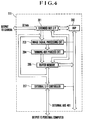
- Fig. 4 is a system block diagram of an extended card to be used for the digital electronic camera of a second embodiment of this invention. This embodiment differs from the first embodiment only in the internal arrangement of the extended card.
- an extended bus interface (I/F) controller 201 is provided for the transfer of digital data on the extended card interface.
- a digital signal processor (hereinafter referred to as DSP) 202 is arranged to carry out compressing and expanding processes and to communicate with a host computer through an external interface.
- DSP digital signal processor
- a digital pickup image signal processing circuit 203 is arranged to perform a pickup image signal processing action on unprocessed image data.
- a thinning-out process circuit 204 is arranged to thin out a signal which has been subjected to the pickup image signal processing action in the vertical and horizontal space directions and in respect of the number of images per unit time.
- a buffer memory 205 is arranged to intermediately operate for data transfer to be made between an extended bus, the thinning process circuit, the DSP and the external interface.
- An external interface controller 207 is, for example, an SCSI controller and is arranged to control communication with an external bus 401.
- the external bus 401 is arranged to connect the camera of this embodiment with the host computer.
- bit width of the extended bus interface is arranged to be larger than that of the first embodiment, so that the data transfer can be made faster than the first embodiment.
- the second embodiment When the extended card is not mounted, the second embodiment operates in exactly the same manner as the first embodiment. Therefore, the following describes the operation of the second embodiment to be performed with the extended card mounted on the camera body thereof.
- the DSP 202 receives the data from the extended bus interface 201 and compresses the data. After that, the compressed data is recorded on the recording medium 101 through the extended bus interface 201, the memory bus controller 102 and the recording medium interface 104.
- the DSP 202 is notified of termination of the sound recording by the operation part control CPU 4 through the signal processing system control CPU 13 either when cancellation of the sound recording instruction given by the operator through the operation part 15 is detected by the operation part control CPU 4 or when the lapse of a predetermined period of time prompts the CPU 4 to consider the sound recording to be canceled.
- Unprocessed image data is then converted into uncompressed image data and is transferred to the buffer memory 205 in the same manner as the function (2-1) of the first embodiment.
- the DSP 202 does not begin to perform image compressing and recording actions until the DSP 202 receives notice of termination of sound recording from the signal processing system control CPU 13.
- the signal processing system control CPU 13 controls the memory bus controller 102 in such a way as to transfer the image data to the extended interface 110.
- the signal processing system control CPU 13 then transfers also sound data to the extended interface 110, in the same manner as the function (2-2) of the first embodiment.
- the DSP 202 receives the above-stated data from the extended bus interface 201 and compresses the data.
- the compressed data is recorded on the recording medium 101 through the extended interface 110, the memory bus controller 102 and the recording medium interface 104. Since the width of the bus between the camera body is wider than that of the first embodiment, the second embodiment has an ample transmission capability. Therefore, the second embodiment permits simultaneous input and output of the image data and the sound data in the manner described above.
- the operation part control CPU 4 notifies the DSP 202 of termination of sound recording through the signal processing system control CPU 13 when cancellation of the instruction given by the operator through the operation part 15 for sound recording is detected or when the operation part control CPU 4 is prompted to consider the sound recording to be canceled by the lapse of a predetermined period of time.
- the DSP 202 compresses uncompressed image data stored in the buffer memory 205 and records the compressed image data on the recording medium 101 through the extended bus interface 110, the memory bus controller 102 and the recording medium interface 104.
- the DSP 202 initializes the pickup image signal processing circuit 203 and the thinning-out process circuit 204 to make them ready for receiving unprocessed image data from the extended bus interface 201.
- the unprocessed image data is processed by the pickup image signal processing circuit 203 into luminance and color information.
- the information is, if necessary, thinned out by the thinning-out process circuit 204 and is transferred to the external interface controller 207 through the buffer memory 205.
- the memory bus controller 102 generates an interruption into the signal processing system control CPU 13 every time the transfer of one horizontal scanning amount of data comes to an end.
- the signal processing system control CPU 13 causes its internal buffer to store therein an audio (sound) signal sampled through the A/D converter 24 at a predetermined frequency defined by its internal timer.
- the buffering amount of the buffer is 4 to 6 bytes per horizontal scanning in the case where the sampling frequency is 44.1 KHz, stereophonic, and a quantizing number is 8 bits (the buffering amount is 8 to 12 bytes if the quantizing number is 16 bits).
- the signal processing system control CPU 13 transfers the 4 to 6 bytes of data stored in its internal buffer to the DSP 202 through the memory bus controller 102 and the extended interface 110.
- the sound data is transferred by the DSP 202 to the external interface controller 207 via the buffer memory 205.
- the image data and the sound data are transferred to the external bus 401 in a time-division multiplexing manner. This action continues until an instruction for termination is given in one way or another from the external bus. For example, if an SCSI is used, the instruction for termination is given with a condition of attention generated by the host computer.
- the second embodiment is the same as the first embodiment.
- S byte/sec
- F frame/sec
- sampling frequency for sounds to be f Hz
- n bytes
- S ⁇ M ⁇ F + f ⁇ n the frame rate
- F the thinning-out process should be carried out in the spatial directions to suppress the average amount of data per image frame to obtain a relation which is expressed as follows: M ⁇ [S - f ⁇ n] / F
- the apparatus of this invention is capable of controlling mechanical, operation and operation display parts related to shooting in accordance with instructions given from the host computer 112 through the external bus 401.
- An instruction coming through the external bus 401 is sent to the operation part control CPU 4 through the external interface controller 207, the extended bus interface 201, the memory bus controller 102 and the signal processing system control CPU 13.
- the instruction is carried out by the operation part control CPU 4 by regarding data thus received as a command.
- data stored as internal data by the operation part control CPU 4 can be sent to the host computer 112 through a reverse route.
- Such data relates to, for example, obtaining the result of distance measurement, designation of focusing, obtaining a current zooming state, setting a zooming value, obtaining data of light measurement, designation of an aperture value, designation of exposure correction, obtaining the current value of exposure correction, commencement or inhibition of a process of charging a flash device, commencement or inhibition of flashing, setting flash light distribution characteristic for zooming, obtaining voltage value of a power supply disposed within the camera, finding the states of operation members of the operation part such as a release button, a zoom button, a barrier switch, a frame feeding or returning button, a shooting mode setting button, etc., and setting the contents of a display to be made at the operation display part.
- motion images can be obtained not only at an ordinary video frame rate (30 frames per sec) but also at other frame rates such as 15 frames per sec, 10 frames per sec, etc. Further, by arranging reference signal transmitters of a plurality of different kinds and by selectively using them to effect change-over of the frequency dividing ratio, it is also possible to obtain motion images at a frame rate other than one integer-th of 30 frames per sec.
- the data does not have to be expanded and is subjected as it is to the thinning-out process or an interpolation process according to the image size of the display buffer memory 12. After that, the data is transferred to the display buffer memory 12 through the extended interface controller 110 and the memory bus controller 102.
- the host computer 112 issues an instruction through the external bus 401 to the camera of this embodiment. Image data is then transferred from the host computer 112 to the camera to be recorded on the recording medium 101.
- the image data transferred from the host computer 112 may be in the form of an unprocessed image, a compressed image or an uncompressed image.
- the image data thus received is recorded on the recording medium 101 in the form of a compressed image.
- the compressed image data coming through the external interface controller 207 is recorded on the recording medium 101 through the extended interface controller 110, the memory bus controller 102 and the recording medium interface 104.
- the unprocessed image data coming through the external interface controller 207 is sent to the pickup image signal processing circuit 203 to be converted into luminance and color information in a state of uncompressed image.
- the output of the pickup image signal processing circuit 203 is sent to the buffer memory 205.
- the DSP 202 then has access to the buffer memory 205 to form compressed image data.
- the compressed image data is recorded on the recording medium 101. If the image data received through the external interface controller 207 is uncompressed image data, the image data is compressed before it is recorded on the recording medium 101.
- the conceivable forms of image data to be transferred from the host computer 112 include an unprocessed image, a compressed image and an uncompressed image.
- the conceivable forms of image data to be returned include a compressed image and an uncompressed image.
- the conceivable forms of sound data to be transferred from and returned to the host computer 112 include compressed sounds and uncompressed sounds.
- the unprocessed image data coming in through the external interface controller 207 is sent to the pickup image signal processing circuit 203 and is then stored in the buffer memory 205. After that, the uncompressed image data of the buffer memory 205 is returned to the host computer 112 through the external interface controller 207 either as it is or after it is compressed by the DSP 202.
- the compressed image data coming in through the external interface controller 207 is transferred directly to the buffer memory 205. After the transfer, the data of the buffer memory 205 is expanded by the DSP 202 before it is returned to the host computer 112 through the external interface controller 207.
- the uncompressed image data coming in through the external interface controller 207 is transferred directly to the buffer memory 205. After the transfer, the data of the buffer memory 205 is compressed by the DSP 202 before it is returned to the host computer 112 through the external interface controller 207.
- the DSP 202 receives sound data through the external interface controller 207 and transfers it to the buffer memory 205. After an amount of the sound data corresponding to the capacity of the buffer memory 205 has been transferred, the form of the data of the buffer memory 205 is converted. With its form thus converted, the data is returned to the host computer 112 through the external interface controller 207. This process is repeated until all the sound data on the host computer 112 have been completely processed.
- this function enables the host computer 112 which has a low signal processing capability to process signals at a high speed.
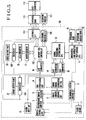
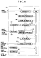
- Figs. 5 and 6 show a camera system arranged according to this invention as a third embodiment thereof.
- an audio signal obtained from a sound input circuit 20 is arranged to be supplied to an A/D converter 611 of an extended card 111 through an extended bus interface.
- the A/D converter 611 and a D/A converter 612 are arranged to have a higher accuracy and a wider bit width than an A/D converter 24 and a D/A converter 25.
- a signal processing DSP 202 is thus enabled to handle sound data of a high quality.
- a signal processing system control CPU 13 is arranged to control a switch circuit 501 to select the output signal of the D/A converter 612, so that a high quality sound can be outputted with the DSP 202 supplying the high quality sound data to the D/A converter 612.
- the third embodiment can record and reproduce high quality sounds with the audio signal processed by the signal processing DSP 202 instead of by the signal processing system control CPU 13.
- sound data of a large bit number is of course either compressed before filing or filed as it is.
- the sound data can be reproduced with little distortion by widening the bit width and by carrying out an oversampling filter process.
- a motion image compressing/expanding circuit 608 is a compressing/expanding circuit arranged to to compress, in real time, uncompressed image data which has been processed by a pickup image signal processing circuit 203 and stored in the buffer memory 205. While the DSP of the first embodiment is arranged to carry out the image compressing or expanding process by software, the third embodiment is arranged to have the image compressing or expanding process carried out in real time by the motion image compressing/expanding circuit 608. Therefore, the compressing/expanding process can be carried out much faster than in the case of the first embodiment.
- a particularly salient advantage resides in that, since the compressed data can be outputted in real time to an external interface controller 207, the data of motion images can be transferred even with the transfer speed of the external interface allowed to be much slower. Further, since compressed data can be expanded by receiving it directly from the external interface without passing it through the signal processing DSP 202, the expanding process can be carried out at a high speed.
- the signal processing DSP 202 can receive via a bus controller 206 the data compressed by the motion image compressing/expanding circuit 608 and transmit it to a recording medium 101. In a case where compressed data recorded on the recording medium 101 is to be expanded, the signal processing DSP 202 transfers the compressed data via the bus controller 206 to the motion image compressing/expanding circuit 608 to have it expanded and stored in the buffer memory 205. The signal processing DSP 202 thus can read out the expanded, uncompressed data from the buffer memory 205. Referring to Fig. 6, the output of the buffer memory 205 is connected to the D/A converter 610 and to the switch circuit 501 through a video encoder 609 and the extended bus interface.
- a signal processing system control CPU 13 is arranged to be capable of causing the image stored in the buffer memory 205 to be displayed by controlling the switch circuit 502 in such a way as to select the output signal of the D/A converter 610.
- a memory having a small number of picture elements is employed as an image display buffer memory 12 for the purpose of displaying an image in a simple state.
- the buffer memory 205 is on the other hand arranged to be capable of displaying an image consisting of the same number of picture elements as an image sensor 6. The display capability thus can be greatly enhanced with the extended card 111 mounted on the camera body 100. Therefore, in a case where a plurality of images are to be reproduced and displayed, the third embodiment is capable of enabling the operator to see more images than in the case of the first embodiment.
- a display of a simple image can be made at a video output part 23 with the switch circuit 502 controlled in such a way as to select the output signal of a preprocessing circuit 9.
- electric energy can be saved by stopping the supply of power to a part including the A/D converter 10, the memory bus controller, 102, the buffer memory 12 and a D/A converter 26.
- Fig. 7 is a block diagram showing by way of example the arrangement of an extended card employed in a fourth embodiment of this invention.
- reference numerals 111 to 612 denotes blocks which are identical with those of Fig. 6.
- Reference numeral 701 denotes a reduced instruction set computer (RISC) CPU.
- a program RAM 702 is arranged to store an operation program of the RISC CPU 701.
- a flash ROM 703 is arranged to store the basic input and output system (BIOS) of the RISC CPU 701.
- BIOS basic input and output system
- a recording medium 101 in which a program of the BIOS level of the RISC CPU 701 is written is first mounted on the camera part 100 of Fig. 5.
- the contents of the recording medium 101 are transferred to the extended card 111 through a recording medium interface 104 and an extended interface 110 under the control of a memory bus controller 102.
- the RISC CPU 701 controls the program data transferred from the camera part 100 to be written into the flash ROM 703 through the extended bus interface.
- a character image which is picked up by the camera can be processed by the RISC CPU 701 to convert it into text data to have it stored in a program RAM, including programs related to the software of translation, image recognition, image synthesis, etc.
- the fourth embodiment has been described as having the recording medium 101 connected to the camera as a supply source of a processing program or a BIOS, the processing program may be supplied from some other information apparatus such as a personal computer through the SCSI bus of the extended card.
- the fourth embodiment is arranged as described above to use the RISC CPU as a processor which permits a high speed computing operation.
- the RISC CPU of course may be replaced with some other processor, such as a CISC (complex instruction set computer) CPU or the like.
- the invention provides a low-priced recording and/or reproducing system when nothing is connected to the extended interface of the system.
- the invention provides a system most apposite to the desire of the users by varying the functions of the units to be inserted into the extended interface. Therefore, a system which is not expensive as a whole can be obtained in accordance with this invention.
- a recording and/or reproducing apparatus includes an optical system arranged to form an optical image, a photo-electric conversion part arranged to convert the optical imaged into an electrical signal, an A/D conversion circuit arranged to convert the electrical signal and/or an audio signal into a digital signal, a connector arranged to permit mounting and demounting a recording medium on which the digital signal obtained from the A/D conversion circuit is to be recorded, and a signal processing part for processing and converting the digital signal.
- the signal processing part is arranged to be mountable and demountable on and from the apparatus.
Landscapes
- Engineering & Computer Science (AREA)
- Multimedia (AREA)
- Signal Processing (AREA)
- General Engineering & Computer Science (AREA)
- Computing Systems (AREA)
- Software Systems (AREA)
- Television Signal Processing For Recording (AREA)
Applications Claiming Priority (3)
| Application Number | Priority Date | Filing Date | Title |
|---|---|---|---|
| JP8516693 | 1993-03-22 | ||
| JP08516693A JP3548191B2 (ja) | 1993-03-22 | 1993-03-22 | カメラ |
| JP85166/93 | 1993-03-22 |
Publications (3)
| Publication Number | Publication Date |
|---|---|
| EP0617542A2 true EP0617542A2 (de) | 1994-09-28 |
| EP0617542A3 EP0617542A3 (de) | 1995-10-11 |
| EP0617542B1 EP0617542B1 (de) | 2000-07-05 |
Family
ID=13851084
Family Applications (1)
| Application Number | Title | Priority Date | Filing Date |
|---|---|---|---|
| EP94104440A Expired - Lifetime EP0617542B1 (de) | 1993-03-22 | 1994-03-21 | Aufzeichnungs- und/oder Wiedergabegerät |
Country Status (4)
| Country | Link |
|---|---|
| US (2) | US5535011A (de) |
| EP (1) | EP0617542B1 (de) |
| JP (1) | JP3548191B2 (de) |
| DE (1) | DE69425080T2 (de) |
Cited By (13)
| Publication number | Priority date | Publication date | Assignee | Title |
|---|---|---|---|---|
| WO1996002106A1 (en) * | 1994-07-09 | 1996-01-25 | Vision 1 International Limited | Digitally networked video camera |
| EP0669752A3 (de) * | 1994-02-28 | 1996-06-05 | Eastman Kodak Co | Intelligente digitale Bildspeicherung für eine elektronische Kamera. |
| GB2296156A (en) * | 1994-07-09 | 1996-06-19 | Vision 1 Int Ltd | Digitally networked video camera |
| WO1996026602A1 (en) * | 1995-02-23 | 1996-08-29 | Avid Technology, Inc. | Portable moving picture recording device including switching control for multiple data flow configurations |
| EP0756225A3 (de) * | 1995-07-24 | 1998-01-21 | Canon Kabushiki Kaisha | Bildaufnahmesystem und Signalverarbeitungsgerät von aufgenommenen Bildern |
| WO1998049835A1 (en) * | 1997-04-30 | 1998-11-05 | Winnov, L., P. | Video and audio interface for a computer |
| EP0929972A4 (de) * | 1996-09-30 | 1999-11-10 | Flashpoint Technology Inc | Verfahren und system zur erstellung einer echtzeit-diavorführung mit klangspur unter verwendung einer digitalen kamera |
| EP0897634A4 (de) * | 1996-05-06 | 2000-12-20 | Cimatrix | Intelligente ccd-kamera mit progressiver abtastung |
| US6977673B1 (en) | 1995-02-23 | 2005-12-20 | Avid Technology, Inc. | Portable moving picture recording device including switching control for multiple data flow configurations |
| US7623754B1 (en) | 1995-02-23 | 2009-11-24 | Avid Technology, Inc. | Motion picture recording device using digital, computer-readable non-linear media |
| US8102457B1 (en) | 1997-07-09 | 2012-01-24 | Flashpoint Technology, Inc. | Method and apparatus for correcting aspect ratio in a camera graphical user interface |
| US8127232B2 (en) | 1998-12-31 | 2012-02-28 | Flashpoint Technology, Inc. | Method and apparatus for editing heterogeneous media objects in a digital imaging device |
| US9224145B1 (en) | 2006-08-30 | 2015-12-29 | Qurio Holdings, Inc. | Venue based digital rights using capture device with digital watermarking capability |
Families Citing this family (51)
| Publication number | Priority date | Publication date | Assignee | Title |
|---|---|---|---|---|
| JP3548191B2 (ja) * | 1993-03-22 | 2004-07-28 | キヤノン株式会社 | カメラ |
| US5739850A (en) | 1993-11-30 | 1998-04-14 | Canon Kabushiki Kaisha | Apparatus for improving the image and sound processing capabilities of a camera |
| EP0683596B1 (de) * | 1994-05-18 | 2000-08-30 | Sharp Kabushiki Kaisha | Kartenartige Kamera mit Bildverarbeitungsfunktion |
| EP0705037B1 (de) * | 1994-09-28 | 2002-12-04 | Canon Kabushiki Kaisha | Bildeingabevorrichtung |
| US6670985B2 (en) | 1994-09-28 | 2003-12-30 | Canon Kabushiki Kaisha | Image sensing apparatus including a card device connectable to an information processing device |
| JP3893480B2 (ja) * | 1994-09-28 | 2007-03-14 | 株式会社リコー | デジタル電子カメラ |
| JPH08124294A (ja) * | 1994-10-26 | 1996-05-17 | Canon Inc | 記録再生システム |
| US6111604A (en) * | 1995-02-21 | 2000-08-29 | Ricoh Company, Ltd. | Digital camera which detects a connection to an external device |
| US5999406A (en) | 1995-02-23 | 1999-12-07 | Avid Technology, Inc. | Dockable electronic equipment container |
| US7532807B2 (en) | 1995-04-07 | 2009-05-12 | Avid Technology, Inc. | Combined editing system and digital moving picture recording system |
| JPH0969978A (ja) * | 1995-08-30 | 1997-03-11 | Sanyo Electric Co Ltd | 撮像装置 |
| KR0164044B1 (ko) * | 1995-09-25 | 1999-01-15 | 김광호 | 방문자 확인 시스템 및 그 방법 |
| US6282362B1 (en) * | 1995-11-07 | 2001-08-28 | Trimble Navigation Limited | Geographical position/image digital recording and display system |
| JP3631838B2 (ja) * | 1996-02-21 | 2005-03-23 | チノン株式会社 | 外部記憶装置およびカメラシステム |
| JPH09247627A (ja) * | 1996-03-05 | 1997-09-19 | Sony Corp | 記録媒体記録再生装置付ビデオカメラおよびその制御方法 |
| JPH1013779A (ja) * | 1996-06-25 | 1998-01-16 | Nikon Corp | 情報処理装置 |
| WO1998011719A1 (fr) * | 1996-09-13 | 1998-03-19 | Hitachi, Ltd. | Dispositif de prise d'image |
| US6256063B1 (en) * | 1996-10-02 | 2001-07-03 | Fuji Photo Film Co., Ltd. | Image signal processing unit and electronic still camera |
| DE69717139T2 (de) * | 1996-12-04 | 2003-10-02 | Matsushita Electric Industrial Co., Ltd. | Vorrichtung zur aufnahme und wiedergabe von hochauflösenden und dreidimensionalen bildern mit optischer speicherplatte |
| CA2278810A1 (en) * | 1997-01-29 | 1998-07-30 | Winbond Systems Laboratory, Inc. | Digital moving and still picture capture adaptor for moving picture video camera |
| JP3268995B2 (ja) * | 1997-02-27 | 2002-03-25 | 三洋電機株式会社 | デジタルカメラ |
| US6930709B1 (en) * | 1997-12-04 | 2005-08-16 | Pentax Of America, Inc. | Integrated internet/intranet camera |
| US6118482A (en) * | 1997-12-08 | 2000-09-12 | Intel Corporation | Method and apparatus for electrical test of CMOS pixel sensor arrays |
| US6226422B1 (en) * | 1998-02-19 | 2001-05-01 | Hewlett-Packard Company | Voice annotation of scanned images for portable scanning applications |
| JP4164202B2 (ja) * | 1998-10-08 | 2008-10-15 | キヤノン株式会社 | 電子機器、電子機器の駆動方法、及びコンピュータ読み取り可能な記憶媒体 |
| US6154210A (en) * | 1998-11-25 | 2000-11-28 | Flashpoint Technology, Inc. | Method and system for implementing button interface compatibility in touch-screen equipped digital imaging device |
| TW573749U (en) * | 1998-12-16 | 2004-01-21 | Ibm | Digital camera with automatic data upload, recording medium therefor, computer system therefor, and digital picture thereof |
| US6714724B1 (en) * | 1999-08-05 | 2004-03-30 | Bradley Steven Cook | Portable device for capturing image and sound data including compact memory and board arrangement |
| US6378010B1 (en) * | 1999-08-10 | 2002-04-23 | Hewlett-Packard Company | System and method for processing compressed audio data |
| US7339615B2 (en) | 1999-12-22 | 2008-03-04 | Fujifilm Corporation | Method and apparatus for capturing images and for recording data that includes image data and audio data separately prepared from the image data |
| JP3922859B2 (ja) * | 1999-12-28 | 2007-05-30 | 株式会社リコー | 画像処理装置、画像処理方法およびその方法をコンピュータに実行させるプログラムを記録したコンピュータ読み取り可能な記録媒体 |
| JP4286420B2 (ja) * | 2000-02-18 | 2009-07-01 | Hoya株式会社 | インターネットカメラ |
| JP2001238199A (ja) * | 2000-02-25 | 2001-08-31 | Asahi Optical Co Ltd | インターネットカメラシステム |
| JP4262384B2 (ja) * | 2000-02-28 | 2009-05-13 | Hoya株式会社 | インターネットカメラ |
| US6385404B1 (en) | 2000-08-22 | 2002-05-07 | Eastman Kodak Company | Dual film image and electronic image capture camera capable of combining captured electronic images in a single multi-(index-) image |
| JP3599654B2 (ja) * | 2000-09-12 | 2004-12-08 | キヤノン株式会社 | 画像データの送信及び保存方法 |
| US7562380B2 (en) * | 2000-10-27 | 2009-07-14 | Hoya Corporation | Internet camera system |
| US7242850B2 (en) * | 2001-02-23 | 2007-07-10 | Eastman Kodak Company | Frame-interpolated variable-rate motion imaging system |
| US20020146133A1 (en) * | 2001-03-31 | 2002-10-10 | Lee Kyu Ho | Portable multimedia reproducing apparatus |
| US7239758B2 (en) * | 2002-02-07 | 2007-07-03 | Nikon Corporation | Signal processing device for reducing noise of image signal, signal processing program, and signal processing method |
| AU2003241385A1 (en) | 2002-05-03 | 2003-11-17 | Pixearth, Corporation | A system to navigate within images spatially referenced to a computed space |
| JP4322144B2 (ja) * | 2003-03-17 | 2009-08-26 | 株式会社リコー | 画像撮影装置 |
| US7197189B2 (en) * | 2003-05-15 | 2007-03-27 | Hewlett-Packard Development Company, L.P. | System and method having removable storage medium with data compression |
| US20050055483A1 (en) * | 2003-08-22 | 2005-03-10 | Devlin William Lee | System and method for file comperssion |
| JP2005123858A (ja) * | 2003-10-16 | 2005-05-12 | Mega Chips Corp | カメラ制御装置 |
| US20070121670A1 (en) * | 2005-11-29 | 2007-05-31 | Delta Electronics, Inc. | Method for converting, editing and modifying communication protocol |
| JP2009147549A (ja) * | 2007-12-12 | 2009-07-02 | Samsung Techwin Co Ltd | 動画像記録装置、動画像再生装置及びプログラム |
| JP7425569B2 (ja) * | 2019-09-20 | 2024-01-31 | キヤノン株式会社 | 撮像装置、デバイス、制御方法及びプログラム |
| JP7441017B2 (ja) * | 2019-09-20 | 2024-02-29 | キヤノン株式会社 | デバイス、撮像装置、制御方法及びプログラム |
| JP7441016B2 (ja) * | 2019-09-20 | 2024-02-29 | キヤノン株式会社 | 撮像装置、情報処理装置、制御方法及びプログラム |
| JP2022068663A (ja) * | 2020-10-22 | 2022-05-10 | キヤノン株式会社 | 撮像装置、情報処理方法、及びプログラム |
Family Cites Families (9)
| Publication number | Priority date | Publication date | Assignee | Title |
|---|---|---|---|---|
| EP0372514B1 (de) * | 1988-12-06 | 1997-03-05 | Canon Kabushiki Kaisha | Bildaufnahmesystem |
| EP0390421B1 (de) * | 1989-03-30 | 1994-07-06 | Canon Kabushiki Kaisha | Stehbild-Videokamera |
| JP2797404B2 (ja) * | 1989-04-20 | 1998-09-17 | ソニー株式会社 | 動画像データの記録方式 |
| US5231501A (en) * | 1989-05-25 | 1993-07-27 | Asahi Kogaku Kogyo Kabushiki Kaisha | Still video apparatus |
| JP3226271B2 (ja) * | 1989-07-27 | 2001-11-05 | オリンパス光学工業株式会社 | ディジタル電子スチルカメラ |
| JP2876258B2 (ja) * | 1991-01-23 | 1999-03-31 | 株式会社リコー | デジタル電子スチルカメラ |
| JP3548191B2 (ja) * | 1993-03-22 | 2004-07-28 | キヤノン株式会社 | カメラ |
| US5374955A (en) * | 1993-12-03 | 1994-12-20 | Hitachi, Ltd. | High-definition imaging device, and apparatuses for recording and playing back high-definition picture information |
| JPH097665A (ja) * | 1995-06-22 | 1997-01-10 | Morimatsu:Kk | インナー式端子台 |
-
1993
- 1993-03-22 JP JP08516693A patent/JP3548191B2/ja not_active Expired - Fee Related
-
1994
- 1994-03-18 US US08/210,565 patent/US5535011A/en not_active Expired - Lifetime
- 1994-03-21 EP EP94104440A patent/EP0617542B1/de not_active Expired - Lifetime
- 1994-03-21 DE DE69425080T patent/DE69425080T2/de not_active Expired - Lifetime
-
1996
- 1996-03-12 US US08/614,041 patent/US6229954B1/en not_active Expired - Lifetime
Cited By (20)
| Publication number | Priority date | Publication date | Assignee | Title |
|---|---|---|---|---|
| EP0669752A3 (de) * | 1994-02-28 | 1996-06-05 | Eastman Kodak Co | Intelligente digitale Bildspeicherung für eine elektronische Kamera. |
| GB2296156A (en) * | 1994-07-09 | 1996-06-19 | Vision 1 Int Ltd | Digitally networked video camera |
| WO1996002106A1 (en) * | 1994-07-09 | 1996-01-25 | Vision 1 International Limited | Digitally networked video camera |
| AU716516B2 (en) * | 1995-02-23 | 2000-02-24 | Avid Technology, Inc. | Motion picture recording device using digital, computer-readable non-linear media |
| WO1996026602A1 (en) * | 1995-02-23 | 1996-08-29 | Avid Technology, Inc. | Portable moving picture recording device including switching control for multiple data flow configurations |
| WO1996026601A3 (en) * | 1995-02-23 | 1996-09-26 | Avid Technology Inc | Motion picture recording device using digital, computer-readable non-linear media |
| US7623754B1 (en) | 1995-02-23 | 2009-11-24 | Avid Technology, Inc. | Motion picture recording device using digital, computer-readable non-linear media |
| AU710297B2 (en) * | 1995-02-23 | 1999-09-16 | Avid Technology, Inc. | Portable moving picture recording device including switching control for multiple data flow configurations |
| US6977673B1 (en) | 1995-02-23 | 2005-12-20 | Avid Technology, Inc. | Portable moving picture recording device including switching control for multiple data flow configurations |
| EP0756225A3 (de) * | 1995-07-24 | 1998-01-21 | Canon Kabushiki Kaisha | Bildaufnahmesystem und Signalverarbeitungsgerät von aufgenommenen Bildern |
| US6642958B2 (en) * | 1995-07-24 | 2003-11-04 | Canon Kabushiki Kaisha | Image pickup system and picked-up image signal processing apparatus |
| US5978020A (en) * | 1995-07-24 | 1999-11-02 | Canon Kabushiki Kaisha | Image pickup system adaptable to computer processing power and/or display |
| EP0897634A4 (de) * | 1996-05-06 | 2000-12-20 | Cimatrix | Intelligente ccd-kamera mit progressiver abtastung |
| EP0929972A4 (de) * | 1996-09-30 | 1999-11-10 | Flashpoint Technology Inc | Verfahren und system zur erstellung einer echtzeit-diavorführung mit klangspur unter verwendung einer digitalen kamera |
| WO1998049835A1 (en) * | 1997-04-30 | 1998-11-05 | Winnov, L., P. | Video and audio interface for a computer |
| US8102457B1 (en) | 1997-07-09 | 2012-01-24 | Flashpoint Technology, Inc. | Method and apparatus for correcting aspect ratio in a camera graphical user interface |
| US8970761B2 (en) | 1997-07-09 | 2015-03-03 | Flashpoint Technology, Inc. | Method and apparatus for correcting aspect ratio in a camera graphical user interface |
| US8127232B2 (en) | 1998-12-31 | 2012-02-28 | Flashpoint Technology, Inc. | Method and apparatus for editing heterogeneous media objects in a digital imaging device |
| US8972867B1 (en) | 1998-12-31 | 2015-03-03 | Flashpoint Technology, Inc. | Method and apparatus for editing heterogeneous media objects in a digital imaging device |
| US9224145B1 (en) | 2006-08-30 | 2015-12-29 | Qurio Holdings, Inc. | Venue based digital rights using capture device with digital watermarking capability |
Also Published As
| Publication number | Publication date |
|---|---|
| EP0617542B1 (de) | 2000-07-05 |
| DE69425080D1 (de) | 2000-08-10 |
| JP3548191B2 (ja) | 2004-07-28 |
| JPH06276471A (ja) | 1994-09-30 |
| US6229954B1 (en) | 2001-05-08 |
| US5535011A (en) | 1996-07-09 |
| EP0617542A3 (de) | 1995-10-11 |
| DE69425080T2 (de) | 2001-03-15 |
Similar Documents
| Publication | Publication Date | Title |
|---|---|---|
| US5535011A (en) | Recording and/or reproducing apparatus | |
| US5786851A (en) | Imaging system for recording or reproducing a photographed image signal or input audio signal as a digital signal | |
| US5231501A (en) | Still video apparatus | |
| JP3542653B2 (ja) | 電子スチルカメラにおける画像データ伝送システム | |
| US5805214A (en) | Ultra small video camera and a video camera system in use thereof | |
| US5614946A (en) | Still camera with time division recording of audio and video signals | |
| US4901160A (en) | Electronic camera | |
| US5170262A (en) | Electronic camera | |
| US4897732A (en) | Electronic camera | |
| JPH04504945A (ja) | 互換性のあるピックアップ装置を備えた電子イメージ化装置 | |
| US5875280A (en) | Recording apparatus having variably settable compression ratio | |
| US5774623A (en) | Video image and audio sound signal processor having signal multiplexer and single data compression system for digital video recording and playback apparatus | |
| US5155584A (en) | Image recording reproducing apparatus switching image sensor signals or reproduced signals to an A/D converter | |
| JP2004328034A (ja) | 撮像装置、動画ファイルの記録制御方法及びプログラム | |
| US5740303A (en) | Magnetic recording system and method for a digital still video recorder | |
| US7750941B2 (en) | Electronic camera and recording and regenerating method | |
| JPH07322195A (ja) | 画像記録再生装置及び画像・音声記録再生装置 | |
| JP2658236B2 (ja) | 情報処理装置 | |
| US20020110359A1 (en) | Recording apparatus and reproduction apparatus | |
| JPH0837634A (ja) | 画像記録装置 | |
| JP2000224540A (ja) | 画像ファイル装置 | |
| EP0653883A2 (de) | Videosystem mit einer Mehrzahl von trennbaren Einheiten | |
| JPH0722358B2 (ja) | 画像情報記録装置 | |
| EP1575286A2 (de) | Kombinierte Kamerarecorder und Standbildkamera | |
| JP4163297B2 (ja) | 電子スチルカメラ |
Legal Events
| Date | Code | Title | Description |
|---|---|---|---|
| PUAI | Public reference made under article 153(3) epc to a published international application that has entered the european phase |
Free format text: ORIGINAL CODE: 0009012 |
|
| AK | Designated contracting states |
Kind code of ref document: A2 Designated state(s): DE FR GB |
|
| PUAL | Search report despatched |
Free format text: ORIGINAL CODE: 0009013 |
|
| AK | Designated contracting states |
Kind code of ref document: A3 Designated state(s): DE FR GB |
|
| 17P | Request for examination filed |
Effective date: 19960226 |
|
| 17Q | First examination report despatched |
Effective date: 19980212 |
|
| GRAG | Despatch of communication of intention to grant |
Free format text: ORIGINAL CODE: EPIDOS AGRA |
|
| GRAG | Despatch of communication of intention to grant |
Free format text: ORIGINAL CODE: EPIDOS AGRA |
|
| GRAG | Despatch of communication of intention to grant |
Free format text: ORIGINAL CODE: EPIDOS AGRA |
|
| GRAH | Despatch of communication of intention to grant a patent |
Free format text: ORIGINAL CODE: EPIDOS IGRA |
|
| GRAH | Despatch of communication of intention to grant a patent |
Free format text: ORIGINAL CODE: EPIDOS IGRA |
|
| GRAH | Despatch of communication of intention to grant a patent |
Free format text: ORIGINAL CODE: EPIDOS IGRA |
|
| GRAA | (expected) grant |
Free format text: ORIGINAL CODE: 0009210 |
|
| AK | Designated contracting states |
Kind code of ref document: B1 Designated state(s): DE FR GB |
|
| REF | Corresponds to: |
Ref document number: 69425080 Country of ref document: DE Date of ref document: 20000810 |
|
| ET | Fr: translation filed | ||
| PLBE | No opposition filed within time limit |
Free format text: ORIGINAL CODE: 0009261 |
|
| STAA | Information on the status of an ep patent application or granted ep patent |
Free format text: STATUS: NO OPPOSITION FILED WITHIN TIME LIMIT |
|
| 26N | No opposition filed | ||
| REG | Reference to a national code |
Ref country code: GB Ref legal event code: IF02 |
|
| PGFP | Annual fee paid to national office [announced via postgrant information from national office to epo] |
Ref country code: DE Payment date: 20120331 Year of fee payment: 19 |
|
| PGFP | Annual fee paid to national office [announced via postgrant information from national office to epo] |
Ref country code: GB Payment date: 20120223 Year of fee payment: 19 |
|
| PGFP | Annual fee paid to national office [announced via postgrant information from national office to epo] |
Ref country code: FR Payment date: 20120413 Year of fee payment: 19 |
|
| GBPC | Gb: european patent ceased through non-payment of renewal fee |
Effective date: 20130321 |
|
| REG | Reference to a national code |
Ref country code: FR Ref legal event code: ST Effective date: 20131129 |
|
| REG | Reference to a national code |
Ref country code: DE Ref legal event code: R119 Ref document number: 69425080 Country of ref document: DE Effective date: 20131001 |
|
| PG25 | Lapsed in a contracting state [announced via postgrant information from national office to epo] |
Ref country code: DE Free format text: LAPSE BECAUSE OF NON-PAYMENT OF DUE FEES Effective date: 20131001 Ref country code: FR Free format text: LAPSE BECAUSE OF NON-PAYMENT OF DUE FEES Effective date: 20130402 Ref country code: GB Free format text: LAPSE BECAUSE OF NON-PAYMENT OF DUE FEES Effective date: 20130321 |