EP0617683B1 - Vorrichtung zum trennen von zwei folien aus biegsamem material - Google Patents
Vorrichtung zum trennen von zwei folien aus biegsamem material Download PDFInfo
- Publication number
- EP0617683B1 EP0617683B1 EP93902346A EP93902346A EP0617683B1 EP 0617683 B1 EP0617683 B1 EP 0617683B1 EP 93902346 A EP93902346 A EP 93902346A EP 93902346 A EP93902346 A EP 93902346A EP 0617683 B1 EP0617683 B1 EP 0617683B1
- Authority
- EP
- European Patent Office
- Prior art keywords
- jaw
- sheets
- needles
- jaws
- separating
- Prior art date
- Legal status (The legal status is an assumption and is not a legal conclusion. Google has not performed a legal analysis and makes no representation as to the accuracy of the status listed.)
- Expired - Lifetime
Links
- 229920002994 synthetic fiber Polymers 0.000 claims abstract description 5
- 238000003780 insertion Methods 0.000 claims abstract description 4
- 230000037431 insertion Effects 0.000 claims abstract description 4
- 239000000463 material Substances 0.000 claims description 9
- 238000000926 separation method Methods 0.000 description 7
- 210000000078 claw Anatomy 0.000 description 6
- 238000004519 manufacturing process Methods 0.000 description 3
- 210000000056 organ Anatomy 0.000 description 2
- 238000013519 translation Methods 0.000 description 2
- 238000013459 approach Methods 0.000 description 1
- 238000000034 method Methods 0.000 description 1
- 238000012986 modification Methods 0.000 description 1
- 230000004048 modification Effects 0.000 description 1
- 239000002985 plastic film Substances 0.000 description 1
- 230000001360 synchronised effect Effects 0.000 description 1
Images
Classifications
-
- B—PERFORMING OPERATIONS; TRANSPORTING
- B65—CONVEYING; PACKING; STORING; HANDLING THIN OR FILAMENTARY MATERIAL
- B65B—MACHINES, APPARATUS OR DEVICES FOR, OR METHODS OF, PACKAGING ARTICLES OR MATERIALS; UNPACKING
- B65B43/00—Forming, feeding, opening or setting-up containers or receptacles in association with packaging
- B65B43/26—Opening or distending bags; Opening, erecting, or setting-up boxes, cartons, or carton blanks
- B65B43/30—Opening or distending bags; Opening, erecting, or setting-up boxes, cartons, or carton blanks by grippers engaging opposed walls, e.g. suction-operated
Definitions
- the present invention relates to a device for separating two sheets of flexible material, in particular two sheets of synthetic material, initially applied one against the other and having to be separated from each other for the insertion of at least one object or accessory between these sheets.
- the device belongs to the kind of those comprising two movable jaws which can be moved towards or away from each other, on either side of the two sheets to be separated, and provided respectively with members able to grip these two sheets and to move them in opposite directions.
- a device of this kind is mainly used to separate two sheets initially superimposed, together forming a sheath or a flattened tube of indefinite length, or a bag of well defined dimensions, view of the opening of the sheath or of the bag for the insertion of at least one rigid object such as a tube, a nozzle or any accessory.
- This known device comprises, on each of the two jaws, claws which are pivotally mounted and which, during their pivoting movement in the operating cycle of the device, should in principle penetrate between the extreme edges of the two sheets, so as to cause their separation, each claw then engaging in a conical recess formed on the corresponding jaw.
- the ends of the two sheets to be spread must be positioned with very high axial precision, relative to the jaws, to be at a very precise point in the trajectory of the claws, failing which the latter cannot be introduced between the two leaves.
- EP-A-0 142 880 also remains relatively complicated and expensive, due to the need for great precision for the production of some of its organs which have a special bevelled shape, and the obligation to machine conical recesses in the jaws.
- the present invention aims to eliminate the above drawbacks, by providing a device for separating two sheets of flexible material which, while remaining relatively simple and economical to manufacture, allows a certain imprecision in the axial positioning of the sheets to be separated, while ensuring a safe separation of these sheets, this device being easy to apply when opening short sachets.
- each movable jaw is pivotally mounted about an axis substantially coinciding with a fixed point of holding the sheets to be separated and is provided, in its part in correspondence with the central region of the sheets to be separated, on the one hand at least one suction cup capable of being connected to a source of vacuum, and turned towards the other jaw, and on the other hand of needles carried by a support mounted movable in translation, relative to the corresponding jaw, in a radial direction relative to the pivot axis of this jaw, the needles of each jaw being located at the face of this jaw facing the other jaw, and being parallel to the direction of movement of their respective movable support, control means being provided on the one hand to rotate the two jaws simultaneously and in opposite directions, and other e part to move the needles by engaging them between the two sheets to spread.
- the invention combines the action of suction cups, gripping the two sheets to be separated by their respective outer faces, and the action of needles intended to be introduced between the two sheets by a simple translational movement, by spreading these leaves, the needles being exactly in the joint plane of the two jaws when the latter are tightened against each other. It should be noted that each flexible sheet is then sandwiched between one of the two movable jaws and the needles associated with this jaw, but that there is no pinching of said sheet since the needles are viewed from their ends, always in the same relative position with respect to the associated jaw.
- the position of the anterior end of the two sheets to be separated is not of decisive importance, and it is sufficient that this end is located between the two jaws, in a region reached by the needles when these the latter approach the associated jaws.
- the pivoting movement of the two jaws makes it possible to move the suction cups on an arc of a circle of which this point is the center, so that the distance between the holding point of the sheets and their gripping point by each jaw remains fixed during the process.
- the proposed device makes it possible to open bags of short length, equal to or less than 100 mm, having to be kept very close to their edge to be opened because of this short length.
- the pivot axis of the jaws being located in the median plane of the device, along which plane the sheets to be spread are brought, it is advantageous that the pivoting movement of the two jaws is guided by lateral slides in an arc of a circle, centered on the pivot axis of the jaws, each jaw comprising two parallel lateral parts, each provided with two rollers or the like engaged in the slide in corresponding arc.
- the pivoting movement of each jaw is perfectly guided, without the need for a mechanical axis along the geometric pivot axis.
- the needles associated with one of the movable jaws are offset transversely with respect to the needles associated with the other movable jaw, so that in the close position of the two jaws, the needles associated with a jaw take place between the needles associated with the other jaw, also in an alternate arrangement, all the needles then being located, parallel to each other, in the joint plane of the two jaws as already indicated above.
- each movable jaw has, on its face facing the other jaw, a series of parallel recesses of semi-cylindrical shape, arranged in correspondence with the transverse positions of all the needles associated with the two jaws, so that in the close position of the two jaws, their respective semi-cylindrical recesses are brought into a coaxial position to define cylindrical housings capable of receiving the different needles.
- These housings can have a very small diameter, so that the sheets remain held by the jaws at a very precise location, and that the introduction of the needles between these sheets is carried out easily.
- all the needles and all the corresponding recesses, formed in the jaws are offset transversely with respect to the positions of the suction cups on these jaws. This avoids any interference between the suction cups and the needles, and therefore any risk of damage to the suction cups by the jaws.
- control means for moving the jaws and the needles are conveniently achievable in the form of jacks, and on the whole the production of the various organs of the device, with their previously described conformations, remains relatively simple and economical.
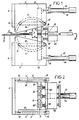
- the device shown in the drawing is intended for the separation of two superimposed sheets 1 and 2 of synthetic material, which are in particular the two faces of a sachet or a flexible pouch, brought horizontally to the device according to an arrow 3.
- the device comprises two parts, one upper and the other lower, symmetrical to each other with respect to the horizontal plane containing the two sheets 1 and 2 to be separated. We will therefore only describe the structure of one of these two parts, the other resulting by symmetry.
- a fixed frame plate 4 On a fixed frame plate 4, arranged vertically and transversely to the direction of arrival of the sheets 1 and 2 (arrow 3), are mounted two lateral flanges 5, vertical and parallel to each other.
- Each lateral puddle 5 has, on its face turned towards the other flange, a slide 6 in an arc of a circle.
- the two slides 6, thus located one opposite the other, are centered on the same horizontal axis 7 which coincides with the holding point of the sheets 1 and 2 to be separated, point where these sheets 1 and 2 can in particular be clamped by means of side clamps 8, not shown in detail but having a known structure.
- Each part of the device has a movable jaw 9, generally presenting itself as a transverse plate.
- the jaw 9 is provided, on its edges close to the flanges 5, with two respective connecting rods 10, mutually parallel and perpendicular to the plane of this jaw 9.
- Each connecting rod 10 is itself provided, towards its ends, with two rollers 11 and 12 which are engaged in the slide 6 in an arc of a circle of the adjacent flange 5.
- the jaw 9 is thus held and guided in order to be able to describe a pivoting movement around the horizontal axis 7. It should be noted that the jaw 9 is positioned in front of the horizontal axis 7, at a distance d from this axis 7 which remains invariable during the pivoting of the jaw 9.
- the pivoting of the jaw 9 is controlled by a jack 13, the body 14 of which is articulated about a fixed axis 15, and the rod of which is hingedly linked to this jaw 9.
- the jaw 9 comprises, housed in suitable recesses, two suction cups 16 which are visible on the face 17 of this jaw facing the other jaw 9.
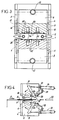
- the complete device thus comprises two pairs of suction cups 16, located in correspondence - see the figure 3. All of these suction cups 16 are able to be connected, by pipes not shown, to a vacuum source.
- each jaw 9 On each jaw 9 is slidably mounted, by means of lateral guide columns 18 perpendicular to this jaw, a mobile support 19 situated on the side opposite to the arrival (arrow 3) of the sheets 1 and 2.
- the mobile support 19 carries a small number of needles 20 located at the face 17 of the jaw 9.
- the needles 20 are thus arranged in a plane which contains the pivot axis 7 of the jaw 9, the tips of the needles 20 being turned towards this axis 7
- the needles 20 carried by the lower movable support 19 are offset, in the transverse direction of the device, relative to the other needles 20 carried by the upper support 19 - see FIG. 3.
- the needles 20 carried by one of the supports 19 can take place between the other needles 20, carried by the other support, when the two jaws 9 are brought together.
- each suction cup 16 is located between a central needle 20 and a lateral needle 20.
- the two jacks 13 are controlled simultaneously, to cause synchronized and symmetrical movements of the two jaws 9.
- the two jacks 21 are also controlled synchronously, to move all the needles 20 simultaneously and in the same direction.
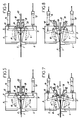
- the operating cycle of the device is illustrated in Figures 4 to 8.
- the flat sachet formed by the two sheets 1 and 2 initially not separated, is advanced along arrow 3 between the two jaws 9 kept apart from one another.
- the clamps 8 are closed and block this sachet.
- the jacks 13 are then controlled to rotate the two jaws 9 in opposite directions, so as to bring them closer.
- the jaws 9 thus clamp the two sheets 1 and 2 together, as shown in FIG. 5.
- the suction cups 16 are placed against the outside faces of the two sheets 1 and 2, while all the needles 20 are brought in the same horizontal plane, coinciding with the joint plane of the two jaws 9.
- the vacuum is applied to the suction cups 16, which then act on the two sheets 1 and 2 in opposite directions.
- the jacks 21 are activated to bring the mobile supports 19 closer to the respective jaws 9.
- Each needle 20 then takes place in one of the cylindrical housings, resulting from two corresponding semi-cylindrical recesses 22, brought into a coaxial arrangement by the clamping of the jaws 9 - see FIG. 6. All the needles 20 are thus engaged, by their points, between the two sheets 1 and 2.
- the combination of the action of the suction cups 16 and the introduction of the needles 20 then ensures a certain opening of the sachet.
- the two jaws 9 pivot around the axis 7 in the direction of their separation, the tips 10 retaining their positions relative to the respective jaws 9.
- the two sheets 1 and 2 are thus clearly separated from each other, in their central regions, without any traction being exerted on these sheets in their part located in front of the clamps 8.
- the widely open end of the bag can then receive tip (s) 23.
- the needles 20 are moved away from the jaws 9 and extracted from the bag, while the vacuum is no longer applied to the suction cups 16.
- the jaws 9 then possibly perform an additional spacing movement, to clear the open bag which can then be removed.
- the device is thus found in its initial state, ready to start a new cycle identical to the previous one.
- the invention is not limited to the sole embodiment of this device for separating two sheets of flexible material which has been described above, by way of example; on the contrary, it embraces all of the variant embodiments and applications respecting the same principle. Thus, one would not depart from the scope of the invention by constructive modifications, concerning for example the number of suction cups or needles, or even the means for controlling the movements, the jacks being replaceable by any equivalent.
- the application variants of the device may relate to a use other than the separation of plastic sheets forming a bag or a different orientation given to this device, its jaws being possibly horizontally movable and not from bottom to top.
Landscapes
- Engineering & Computer Science (AREA)
- Mechanical Engineering (AREA)
- Supplying Of Containers To The Packaging Station (AREA)
- Sheets, Magazines, And Separation Thereof (AREA)
- Shaping Of Tube Ends By Bending Or Straightening (AREA)
- Containers And Plastic Fillers For Packaging (AREA)
- Bending Of Plates, Rods, And Pipes (AREA)
Claims (5)
- Vorrichtung zum Trennen von zwei Folien aus biegsamem Material, insbesondere zwei Kunststoffolien (1, 2), die zunächst aneinanderhängen und die für die Einbringung mindestens eines Gegenstandes oder Zubehörteiles (23) zwischen diese Folien voneinander getrennt werden müssen, mit zwei beweglichen Backen (9), die auf beiden Seiten der voneinander zu trennender Folien (1, 2) aneinander angenähert und voneinander fort bewegt werden können und die jeweils mit Organen versehen sind, mit denen die beiden Folien ergriffen und in entgegengesetzte Richtungen verlagert werden können, dadurch gekennzeichnet, daß jede bewegliche Backe (9) um eine Achse (7) schwenkbar angeordnet ist, die genau mit einem ortsfesten Haltepunkt (8) für die zu trennenden Folien (1, 2) zusammenfällt und in ihrem mit dem Zentralbereich der zu trennenden Folien (1, 2) korrespondierenden Bereich einerseits mit mindestens einem Sauger (16) versehen ist, der mit einer Vakuumquelle verbindbar ist und der anderen Backe zugewandt ist, und andererseits mit Nadeln (20) versehen ist, die von einem Support (19) getragen sind, der relativ zur korrespondierenden Backe (9) translatorisch bewegbar gemäß einer radialen Richtung bezüglich der Schwenkachse (7) dieser Backe (9) angeordnet ist, wobei die Nadeln (20) einer jeden Backe (9) in der Niveaulage der Fläche (17) dieser Backe liegen, die der anderen Backe zugewandt ist und die ferner parallel zur Verlagerungsrichtung ihres jeweiligen beweglichen Supportes (19) liegen, wobei Betätigungsmittel (13, 21) vorgesehen sind, um einerseits die beiden Backen (19) simultan und in entgegengesetzte Richtungen zu verschwenken und um andererseits die Nadeln (20) so zu verlagern, daß sie zwischen die voneinander zu entfernenden Folien (1, 2) eintreten.
- Vorrichtung zum Trennen von zwei Folien aus biegsamem Material nach Anspruch 1, dadurch gekennzeichnet, daß die Schwenkbewegung der beiden Backen (9) durch seitliche, kreisbogenförmige Führungen (6) geführt ist, die zentrisch zur Schwenkachse (7) der Backen liegen, wobei jede Backe (9) zwei parallele seitliche Abschnitte (10) aufweist, die jede mit zwei Rollen (11, 12) oder dergleichen versehen sind, die mit der kreisbogenförmigen entsprechenden Führung (6) in Eingriff stehen.
- Vorrichtung zum Trennen von zwei Folien aus biegsamem Material nach den Ansprüchen 1 oder 2, dadurch gekennzeichnet, daß die der einen bewegbaren Backe (9) zugeordneten Nadeln (20) transversal bezüglich der der anderen beweglichen Backe (9) zugeordneten Nadeln (20) versetzt sind derart, daß sich in der angenäherten Stellung der beiden Backen (9) die der einen Backe zugeordneten Nadeln zwischen den der anderen Backe zugeordneten Nadeln plazieren.
- Vorrichtung zum Trennen von zwei Folien aus biegsamem Material nach einem der Ansprüche 1 - 3, dadurch gekennzeichnet, daß jede bewegliche Backe (9) auf ihrer der anderen Backe zugewandten Fläche eine Reihe von halbzylindrischen parallelen Ausnehmungen (22) aufweist, die in Korrespondenz mit den Transversallagen aller den beiden Backen, (9) zugeordneten Nadeln (20) angeordnet sind, derart, daß in der angenäherten Stellung der Backen (9) ihre halbzylindrischen jeweiligen Ausnehmungen (22) in eine koaxiale Lage zusammengeführt sind, um zylindrische Ausnehmungen zu begrenzen, die die verschiedenen Nadeln (20) aufnehmen können.
- Vorrichtung zum Trennen von zwei Folien aus biegsamem Material nach Anspruch 4, dadurch gekennzeichnet, daß alle Nadeln (20) und alle korrespondierenden Ausnehmungen (22), die in den Backen (9) vorgesehen sind, transversal bezüglich der Lage von Saugern (16) an diesen Backen (9) versetzt sind, derart, daß die Sauger (16) zwischen den Nadeln (20) liegen.
Applications Claiming Priority (3)
| Application Number | Priority Date | Filing Date | Title |
|---|---|---|---|
| FR9116285 | 1991-12-23 | ||
| FR9116285A FR2685286B1 (fr) | 1991-12-23 | 1991-12-23 | Dispositif pour separer deux feuilles en matiere souple. |
| PCT/FR1992/001201 WO1993012973A1 (fr) | 1991-12-23 | 1992-12-17 | Dispositif pour separer deux feuilles en matiere souple |
Publications (2)
| Publication Number | Publication Date |
|---|---|
| EP0617683A1 EP0617683A1 (de) | 1994-10-05 |
| EP0617683B1 true EP0617683B1 (de) | 1995-05-03 |
Family
ID=9420612
Family Applications (1)
| Application Number | Title | Priority Date | Filing Date |
|---|---|---|---|
| EP93902346A Expired - Lifetime EP0617683B1 (de) | 1991-12-23 | 1992-12-17 | Vorrichtung zum trennen von zwei folien aus biegsamem material |
Country Status (6)
| Country | Link |
|---|---|
| EP (1) | EP0617683B1 (de) |
| KR (1) | KR100234579B1 (de) |
| AT (1) | ATE122008T1 (de) |
| DE (1) | DE69202342T2 (de) |
| FR (1) | FR2685286B1 (de) |
| WO (1) | WO1993012973A1 (de) |
Families Citing this family (1)
| Publication number | Priority date | Publication date | Assignee | Title |
|---|---|---|---|---|
| CN108942142A (zh) * | 2018-08-03 | 2018-12-07 | 深圳控石智能系统有限公司 | 一种分离灯条的安装设备 |
Family Cites Families (3)
| Publication number | Priority date | Publication date | Assignee | Title |
|---|---|---|---|---|
| EP0028119A1 (de) * | 1979-10-29 | 1981-05-06 | BRDR. JORGENSEN ELEKTRO Aps | Apparat zum Verpacken von Gütern, insbesondere eines verdichteten Stapels von Isoliermatten in sackähnliche Behälter |
| DE3503812C2 (de) * | 1985-02-05 | 1986-11-20 | Hans 4000 Düsseldorf Lissner | Vorrichtung zum Aufstecken von Säcken auf einen Füllstutzen |
| DE3605239C2 (de) * | 1986-02-19 | 1994-07-07 | Womako Masch Konstr | Verfahren und Vorrichtung zum Umlegen eines Deckblattes |
-
1991
- 1991-12-23 FR FR9116285A patent/FR2685286B1/fr not_active Expired - Fee Related
-
1992
- 1992-12-17 AT AT93902346T patent/ATE122008T1/de not_active IP Right Cessation
- 1992-12-17 WO PCT/FR1992/001201 patent/WO1993012973A1/fr not_active Ceased
- 1992-12-17 DE DE69202342T patent/DE69202342T2/de not_active Expired - Fee Related
- 1992-12-17 EP EP93902346A patent/EP0617683B1/de not_active Expired - Lifetime
- 1992-12-17 KR KR1019940702182A patent/KR100234579B1/ko not_active Expired - Fee Related
Also Published As
| Publication number | Publication date |
|---|---|
| FR2685286B1 (fr) | 1994-03-25 |
| EP0617683A1 (de) | 1994-10-05 |
| ATE122008T1 (de) | 1995-05-15 |
| DE69202342D1 (de) | 1995-06-08 |
| DE69202342T2 (de) | 1995-10-19 |
| FR2685286A1 (fr) | 1993-06-25 |
| KR100234579B1 (ko) | 1999-12-15 |
| WO1993012973A1 (fr) | 1993-07-08 |
Similar Documents
| Publication | Publication Date | Title |
|---|---|---|
| EP0726453B1 (de) | Vorrichtung zum Rühren und Entnehmen von Blutprodukten aus Proberöhrchen die in einen Gestell angeordnet sind | |
| EP1385762B1 (de) | Greifer für behälter | |
| FR2679818A1 (fr) | Procede et dispositif pour la decoupe de plaques de verre plat. | |
| EP0445044B1 (de) | Rohrbiegevorrichtung mit zwei Biegeköpfen | |
| FR2596948A1 (fr) | Appareil a ebrancher les troncs d'arbres | |
| CA2156687C (fr) | Procede et machine pour la pose de manchons d'etiquetage etirables sur des bouteilles ou similaires | |
| EP0161010B1 (de) | Verfahren und Vorrichtung zum Vereinzeln flexibler Flächengebilde, insbesondere Textilwaren und Maschine zum Vereinzeln und zur Führung dieser Flächengebilde | |
| WO1993012973A1 (fr) | Dispositif pour separer deux feuilles en matiere souple | |
| EP1319479B1 (de) | Vorrichtung zur Übertragung von Objeckten zwischen zwei Positionen | |
| EP0393567A1 (de) | Verfahren und Vorrichtung zum Nieten eines Deckbandes an den Schaufelspitzen eines beschaufelten Rotors | |
| FR2650807A1 (fr) | Dispositif permettant l'ouverture et la fermeture de recipients ayant a vide une forme aplatie | |
| EP3331674B1 (de) | Vertikalmaschine für das schneiden von brot mit greifmitteln für das brot | |
| FR2605617A1 (fr) | Machine pour l'application automatique de feuilles autocollantes sur des articles | |
| FR2471918A2 (fr) | Procede et dispositif pour ouvrir et presenter a une canule de remplissage un sac muni d'une entree a son bord superieur | |
| FR2681584A1 (fr) | Dispositif pour la separation de feuilles en matiere souple. | |
| FR2571070A1 (fr) | Machine automatique a retourner les bas presentant des rouleaux mobiles. | |
| EP3162741B1 (de) | Extraktionsmethode | |
| FR2553031A1 (fr) | Mecanisme et appareil de pliage de plaques, notamment de cliches d'impression | |
| EP0292490B1 (de) | Verfahren und vorrichtung zum greifen eines biegsamen gegenstandes auf einem stapel | |
| EP0636730B1 (de) | Verfahren und Vorrichtung zur automatischen Positionierung von Strümpfen in einer Maschine, um Strumpfhosen zu bilden | |
| EP0220967A1 (de) | Transportvorrichtung für Behälter | |
| EP0076741B1 (de) | Automatisches Bindeverfahren mit einem Band, dessen Enden zum Binden in Gegenrichtung übereinander gelegt werden, und Anordnung zur Durchführung des Verfahrens | |
| EP0987226A1 (de) | Verfahren und Vorrichtung zum Brechen einer Glasscheibe | |
| FR2704178A1 (fr) | Procédé de fabrication d'étuis à soufflets latéraux, et installation pour sa mise en Óoeuvre. | |
| EP0424361B1 (de) | Einrichtungen zum Begrenzen des Flüssigkeitsstromes, insbesondere für die Beutelherstellung aus weichem Material, insbesondere aus Kunststoff |
Legal Events
| Date | Code | Title | Description |
|---|---|---|---|
| PUAI | Public reference made under article 153(3) epc to a published international application that has entered the european phase |
Free format text: ORIGINAL CODE: 0009012 |
|
| 17P | Request for examination filed |
Effective date: 19940615 |
|
| AK | Designated contracting states |
Kind code of ref document: A1 Designated state(s): AT BE CH DE DK ES FR GB GR IE IT LI LU MC NL PT SE |
|
| 17Q | First examination report despatched |
Effective date: 19941014 |
|
| GRAA | (expected) grant |
Free format text: ORIGINAL CODE: 0009210 |
|
| AK | Designated contracting states |
Kind code of ref document: B1 Designated state(s): AT BE CH DE DK ES FR GB GR IE IT LI LU MC NL PT SE |
|
| PG25 | Lapsed in a contracting state [announced via postgrant information from national office to epo] |
Ref country code: NL Free format text: LAPSE BECAUSE OF FAILURE TO SUBMIT A TRANSLATION OF THE DESCRIPTION OR TO PAY THE FEE WITHIN THE PRESCRIBED TIME-LIMIT Effective date: 19950503 Ref country code: MC Free format text: LAPSE BECAUSE OF NON-PAYMENT OF DUE FEES Effective date: 19950503 Ref country code: IT Free format text: LAPSE BECAUSE OF FAILURE TO SUBMIT A TRANSLATION OF THE DESCRIPTION OR TO PAY THE FEE WITHIN THE PRE;WARNING: LAPSES OF ITALIAN PATENTS WITH EFFECTIVE DATE BEFORE 2007 MAY HAVE OCCURRED AT ANY TIME BEFORE 2007. THE CORRECT EFFECTIVE DATE MAY BE DIFFERENT FROM THE ONE RECORDED.SCRIBED TIME-LIMIT Effective date: 19950503 Ref country code: GR Free format text: LAPSE BECAUSE OF FAILURE TO SUBMIT A TRANSLATION OF THE DESCRIPTION OR TO PAY THE FEE WITHIN THE PRESCRIBED TIME-LIMIT Effective date: 19950503 Ref country code: ES Free format text: THE PATENT HAS BEEN ANNULLED BY A DECISION OF A NATIONAL AUTHORITY Effective date: 19950503 Ref country code: DK Effective date: 19950503 Ref country code: AT Effective date: 19950503 |
|
| REF | Corresponds to: |
Ref document number: 122008 Country of ref document: AT Date of ref document: 19950515 Kind code of ref document: T |
|
| REG | Reference to a national code |
Ref country code: IE Ref legal event code: FG4D Free format text: 63749 |
|
| REF | Corresponds to: |
Ref document number: 69202342 Country of ref document: DE Date of ref document: 19950608 |
|
| GBT | Gb: translation of ep patent filed (gb section 77(6)(a)/1977) |
Effective date: 19950602 |
|
| PG25 | Lapsed in a contracting state [announced via postgrant information from national office to epo] |
Ref country code: PT Effective date: 19950803 |
|
| NLV1 | Nl: lapsed or annulled due to failure to fulfill the requirements of art. 29p and 29m of the patents act | ||
| REG | Reference to a national code |
Ref country code: IE Ref legal event code: FD4D Ref document number: 63749 Country of ref document: IE |
|
| PG25 | Lapsed in a contracting state [announced via postgrant information from national office to epo] |
Ref country code: LU Free format text: LAPSE BECAUSE OF NON-PAYMENT OF DUE FEES Effective date: 19951231 Ref country code: IE Free format text: LAPSE BECAUSE OF NON-PAYMENT OF DUE FEES Effective date: 19951231 |
|
| PLBE | No opposition filed within time limit |
Free format text: ORIGINAL CODE: 0009261 |
|
| STAA | Information on the status of an ep patent application or granted ep patent |
Free format text: STATUS: NO OPPOSITION FILED WITHIN TIME LIMIT |
|
| 26N | No opposition filed | ||
| PGFP | Annual fee paid to national office [announced via postgrant information from national office to epo] |
Ref country code: GB Payment date: 19991201 Year of fee payment: 8 |
|
| PGFP | Annual fee paid to national office [announced via postgrant information from national office to epo] |
Ref country code: SE Payment date: 19991206 Year of fee payment: 8 |
|
| PGFP | Annual fee paid to national office [announced via postgrant information from national office to epo] |
Ref country code: DE Payment date: 19991209 Year of fee payment: 8 |
|
| PGFP | Annual fee paid to national office [announced via postgrant information from national office to epo] |
Ref country code: BE Payment date: 19991222 Year of fee payment: 8 |
|
| PGFP | Annual fee paid to national office [announced via postgrant information from national office to epo] |
Ref country code: CH Payment date: 20000302 Year of fee payment: 8 |
|
| PG25 | Lapsed in a contracting state [announced via postgrant information from national office to epo] |
Ref country code: GB Free format text: LAPSE BECAUSE OF NON-PAYMENT OF DUE FEES Effective date: 20001217 |
|
| PG25 | Lapsed in a contracting state [announced via postgrant information from national office to epo] |
Ref country code: SE Free format text: LAPSE BECAUSE OF NON-PAYMENT OF DUE FEES Effective date: 20001218 |
|
| PG25 | Lapsed in a contracting state [announced via postgrant information from national office to epo] |
Ref country code: LI Free format text: LAPSE BECAUSE OF NON-PAYMENT OF DUE FEES Effective date: 20001231 Ref country code: CH Free format text: LAPSE BECAUSE OF NON-PAYMENT OF DUE FEES Effective date: 20001231 Ref country code: BE Free format text: LAPSE BECAUSE OF NON-PAYMENT OF DUE FEES Effective date: 20001231 |
|
| BERE | Be: lapsed |
Owner name: S.A. THIMONNIER Effective date: 20001231 |
|
| GBPC | Gb: european patent ceased through non-payment of renewal fee |
Effective date: 20001217 |
|
| EUG | Se: european patent has lapsed |
Ref document number: 93902346.1 |
|
| REG | Reference to a national code |
Ref country code: CH Ref legal event code: PL |
|
| PG25 | Lapsed in a contracting state [announced via postgrant information from national office to epo] |
Ref country code: DE Free format text: LAPSE BECAUSE OF NON-PAYMENT OF DUE FEES Effective date: 20011002 |
|
| PGFP | Annual fee paid to national office [announced via postgrant information from national office to epo] |
Ref country code: FR Payment date: 20051025 Year of fee payment: 14 |
|
| REG | Reference to a national code |
Ref country code: FR Ref legal event code: ST Effective date: 20070831 |
|
| PG25 | Lapsed in a contracting state [announced via postgrant information from national office to epo] |
Ref country code: FR Free format text: LAPSE BECAUSE OF NON-PAYMENT OF DUE FEES Effective date: 20070102 |