EP0618092A1 - Bandage pneumatique pour véhicule - Google Patents
Bandage pneumatique pour véhicule Download PDFInfo
- Publication number
- EP0618092A1 EP0618092A1 EP94890060A EP94890060A EP0618092A1 EP 0618092 A1 EP0618092 A1 EP 0618092A1 EP 94890060 A EP94890060 A EP 94890060A EP 94890060 A EP94890060 A EP 94890060A EP 0618092 A1 EP0618092 A1 EP 0618092A1
- Authority
- EP
- European Patent Office
- Prior art keywords
- tread
- individual elements
- double
- shaped
- profile
- Prior art date
- Legal status (The legal status is an assumption and is not a legal conclusion. Google has not performed a legal analysis and makes no representation as to the accuracy of the status listed.)
- Granted
Links
- 238000005452 bending Methods 0.000 description 11
- 230000005540 biological transmission Effects 0.000 description 2
- 230000001154 acute effect Effects 0.000 description 1
- 230000000694 effects Effects 0.000 description 1
- 238000012986 modification Methods 0.000 description 1
- 230000004048 modification Effects 0.000 description 1
- 230000008092 positive effect Effects 0.000 description 1
Images
Classifications
-
- B—PERFORMING OPERATIONS; TRANSPORTING
- B60—VEHICLES IN GENERAL
- B60C—VEHICLE TYRES; TYRE INFLATION; TYRE CHANGING; CONNECTING VALVES TO INFLATABLE ELASTIC BODIES IN GENERAL; DEVICES OR ARRANGEMENTS RELATED TO TYRES
- B60C11/00—Tyre tread bands; Tread patterns; Anti-skid inserts
- B60C11/03—Tread patterns
- B60C11/12—Tread patterns characterised by the use of narrow slits or incisions, e.g. sipes
-
- B—PERFORMING OPERATIONS; TRANSPORTING
- B60—VEHICLES IN GENERAL
- B60C—VEHICLE TYRES; TYRE INFLATION; TYRE CHANGING; CONNECTING VALVES TO INFLATABLE ELASTIC BODIES IN GENERAL; DEVICES OR ARRANGEMENTS RELATED TO TYRES
- B60C11/00—Tyre tread bands; Tread patterns; Anti-skid inserts
- B60C11/03—Tread patterns
- B60C11/12—Tread patterns characterised by the use of narrow slits or incisions, e.g. sipes
- B60C11/1204—Tread patterns characterised by the use of narrow slits or incisions, e.g. sipes with special shape of the sipe
- B60C2011/1213—Tread patterns characterised by the use of narrow slits or incisions, e.g. sipes with special shape of the sipe sinusoidal or zigzag at the tread surface
-
- B—PERFORMING OPERATIONS; TRANSPORTING
- B60—VEHICLES IN GENERAL
- B60C—VEHICLE TYRES; TYRE INFLATION; TYRE CHANGING; CONNECTING VALVES TO INFLATABLE ELASTIC BODIES IN GENERAL; DEVICES OR ARRANGEMENTS RELATED TO TYRES
- B60C11/00—Tyre tread bands; Tread patterns; Anti-skid inserts
- B60C11/03—Tread patterns
- B60C11/12—Tread patterns characterised by the use of narrow slits or incisions, e.g. sipes
- B60C11/1236—Tread patterns characterised by the use of narrow slits or incisions, e.g. sipes with special arrangements in the tread pattern
- B60C2011/1245—Tread patterns characterised by the use of narrow slits or incisions, e.g. sipes with special arrangements in the tread pattern being arranged in crossing relation, e.g. sipe mesh
Definitions
- the present invention relates to a vehicle tire intended in particular for winter use with a tread pattern which has tread elements, such as tread blocks or tread bands running in the tire circumferential direction, which are provided with a large number of fine incisions.
- Pneumatic vehicle tires with tread treads have proven themselves very well in recent years, particularly when used in winter driving conditions on snowy or icy surfaces.
- Such a vehicle tire is known for example from AT-B 390.915.
- the tread pattern of this pneumatic vehicle tire has a profile rib running around the center circumferential line of the profile and, to the side of this rib, two rows of blocks composed of tread blocks lined up in the circumferential direction. Both the central rib and the profile blocks in the rows of blocks are each provided with a number of fine incisions running continuously over the block width or the rib width. These fine incisions run essentially parallel to one another and are also essentially equally spaced from one another.
- the fine incisions are also oriented in the axial direction such that they enclose an angle of approximately 30 ° with the axial direction over a large part of their length.
- Tires with such a tread pattern generally have good grip properties.
- the pronounced alignment of the fine incisions in the axial direction means that the tread blocks have a relatively low bending stiffness in the circumferential direction, but rather a rather high bending stiffness in the transverse direction, which impairs the transmission of drive and braking forces and the driving behavior, in particular when cornering.
- the invention is therefore based on the task of designing tread elements in the tread such that, while still having good grip properties, a high bending stiffness is ensured both in the circumferential and in the transverse direction, the measures taken also influencing the bending stiffness in one or the other another direction should be possible.
- profile elements with fine incisions are provided, through which individual elements with an at least approximately double-T-shaped configuration are formed.
- fine incisions are accordingly arranged in profile elements in such a way that that, when viewed from above, they follow at least approximately the contour of a double T-beam.
- these fine incisions form individual elements which have a high bending stiffness both in the circumferential direction and in the axial direction, which gives the entire profile element a high bending stiffness in the circumferential and transverse directions.
- good transmission of drive and braking forces is guaranteed and there is a positive effect on driving behavior.
- the fine incision density in the tread block can still be high to create the desired number of grip edges.
- tread blocks are arranged in the tread pattern, which have a single element with an at least approximately double-T-shaped shape.
- the tread pattern has tread blocks, each of which has a plurality of individual elements with an at least approximately double-T-shaped configuration, with at least two individual elements being arranged such that a bar part is in the space between the bar parts of the second individual element lies. This arrangement allows a higher number of grip edges to be created in a rational manner.
- At least one tread band is arranged in the tread pattern, in which the at least approximately double-T-shaped individual elements are arranged in two rows running in the circumferential direction, the double-T-shaped individual elements being directly adjacent to one another within each row connect and two bar parts of one row in the one row in the circumferential direction immediately consecutive individual elements are arranged with an exact fit between the bar parts of the individual elements of the other row.
- This arrangement is particularly advantageous for a treadmill belt, since the effect of increasing the bending stiffness is very effective.
- the tread block edges or the tread band edges form part of the outer contours of the double-T-shaped individual elements.
- they are within a profile block or a tread band arranged double-T-shaped individual elements at least substantially the same size.
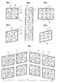
- FIG. 1 shows a top view of a rectangular profile block with a first embodiment of the invention
- FIG. 2 shows a modification of the embodiment according to FIG. 1 for a parallelogram-shaped profile block
- FIG. 3 shows a top view of a section of a profile strip with a further embodiment variant
- 4 and 5 show a further embodiment variant of the invention in a representation analogous to FIGS. 1 and 2
- FIG. 6 shows a schematic plan view of a partial development of a tread pattern designed according to the invention.
- FIGS. 1 and 2 Both drawing figures schematically show a tread block as it can be contained in tread profiles of pneumatic vehicle tires.
- Such profile blocks can have, for example, the rectangular basic shape shown in FIG. 1 or the parallelogram-shaped basic shape shown in FIG. 2.
- the actual block shape in a tread pattern may differ from the simplified basic form of FIGS. 1 and 2 in that the corner edges are bevelled or the profile block edges do not run exactly parallel to one another.
- tread block edges 1a, 1b, 1'a, 1'b has tread block edges 1a, 1b, 1'a, 1'b, the tread block edges 1b, 1'b being those which are aligned in the circumferential direction of the tread pattern Tread block edges 1a would run in the axial direction, and tread block edges 1'a would be inclined at an acute angle with respect to the axial direction of the tire.
- the profile block 1 is provided with a large number of lamellae fine incisions 2 which, viewed in plan view, follow the contour of a plurality of double-T beams nested inside one another.
- the arrangement is such that two double-T beam contours form individual elements, the two beam parts of which run parallel to the block edges 1a and whose connecting webs run parallel to the block edges 1b, two further double-Ts Carrier contours form individual elements, the at least one bar part of which lies in the free space between the bar parts of those individual elements whose connecting webs run in the circumferential direction, that is to say parallel to the block edges 1b.
- the dimensioning of the individual elements in this exemplary embodiment is such that one bar part ends either with the block edges 1a or the block edges 1b.
- Fine cuts 3 possible, especially where it may be appropriate to connect edges of beam parts with profile block edges.
- the fine incisions 2 themselves can extend up to the profile block edges, as a result of which the "beams" are given an asymmetrical shape with respect to the connecting webs.
- All fine incisions 2, 3 have a depth that is preferably at least 30% of the other profile depth.
- the width of these fine incisions 2, 3 is selected in the range between 0.3 and 0.8, in particular between 0.4 and 0.6 mm .
- the arrangement of the fine incisions 2 described creates a fine incision density that is high in the axial direction and in the circumferential direction of the tread pattern. Due to their arrangement in the profile block 1, the fine incisions 2 form elements which have a high bending stiffness both in the circumferential direction and in the axial direction, which transfer to the entire profile block 1, the susceptibility of the profile block 1 to deforming when bending forces occur, which is a bad thing Driving behavior entails significantly reduced.
- the profile block 1 has a large number of grip edges, which is particularly advantageous for tread profiles that are intended to be suitable for winter use.
- the double-T-shaped individual elements shown in FIG. 1 have the same dimensions with each other. Deviating from this illustrated embodiment, however, double-T-shaped individual elements can also be combined with one another, which are of different dimensions. It is also possible to arrange fine incisions in a profile block so that a single double-T-shaped element is formed in the profile block.
- the person skilled in the art has a large number of options for influencing the bending stiffness of the tread block, for example depending on whether it is a block that is closer to the shoulder or in the middle of the tread profile, or the incision density in the circumferential or transverse direction accordingly to change.
- the double-T-shaped individual elements of the fine cuts 2' formed by fine cuts 2 ' have been adapted to the parallelogram shape of the block. Accordingly, in this profile block 1 'fine incisions 2' are present, which create individual elements, the connecting webs of which extend in the circumferential direction and whose beam parts run parallel to the profile block edges 1'a, which are inclined with respect to the axial direction; in the circumferential direction are oriented and the connecting webs are arranged parallel to the profile block edges 1'a.
- This has an impact on the grip properties, since, for example, when driving straight ahead, the traction behavior is influenced by the length components projected in the axial direction of those fine incision sections that run parallel to the profile block edges 1'a.
- tread band 4 shows an arrangement of double-T-shaped individual elements in a tread band 4.
- Such tread bands which run continuously in the circumferential direction, are arranged in particular in the central area of the tread.
- the fine incisions 2 'form in the tread band 4 two rows of double-T-shaped individual elements, these individual elements directly adjoining each other within each row and two bar parts from one row each being arranged with a precise fit between the bar parts of a single element of the other row.
- FIG. 4 The top view of a rectangular profile block 11 is shown in FIG. 4 and a parallelogram-shaped profile block 11 'is shown in FIG. 5.
- the profile block 11 is provided with fine incisions 12.
- the network shown which is formed by the course of the fine incisions 12
- four approximately double-T-shaped individual elements are formed in the profile block 11 in this exemplary embodiment.
- These individual elements result from the fact that both in the axial direction and in the circumferential direction there are provided fine incisions 12 which cross the profile block 11 in wave form, in such a way that adjacent fine incisions 12 have opposing wave forms, so that the troughs and the wave crests are assigned to each other.
- 5 shows this arrangement of the fine incisions 12 'for a parallelogram-shaped profile block 11'.
- FIG. 6 shows a possible embodiment of a tread pattern with tread blocks, which are designed according to the exemplary embodiment according to FIG. 2.
- This tread pattern is designed as a so-called swept or directional profile and is composed of four rows of blocks, each with at least substantially parallelogram-shaped tread blocks 21, through their arrangement three straight circumferential grooves 5 running in the tire circumferential direction and viewed across the tread width B, essentially along V -shaped lateral grooves 6 are formed.
- the present invention is not restricted to the exemplary embodiments shown.
- the arrangement and the number of fine incisions can in particular influence the block profile bending stiffness and the grip behavior.
- sections made according to the invention can have a reduced depth in sections.
Landscapes
- Engineering & Computer Science (AREA)
- Mechanical Engineering (AREA)
- Tires In General (AREA)
- Pulleys (AREA)
- Turning (AREA)
- Moulds For Moulding Plastics Or The Like (AREA)
Applications Claiming Priority (2)
| Application Number | Priority Date | Filing Date | Title |
|---|---|---|---|
| AT661/93 | 1993-04-01 | ||
| AT0066193A AT400554B (de) | 1993-04-01 | 1993-04-01 | Fahrzeugreifen |
Publications (2)
| Publication Number | Publication Date |
|---|---|
| EP0618092A1 true EP0618092A1 (fr) | 1994-10-05 |
| EP0618092B1 EP0618092B1 (fr) | 1996-07-03 |
Family
ID=3496489
Family Applications (1)
| Application Number | Title | Priority Date | Filing Date |
|---|---|---|---|
| EP94890060A Expired - Lifetime EP0618092B1 (fr) | 1993-04-01 | 1994-03-21 | Bandage pneumatique pour véhicule |
Country Status (3)
| Country | Link |
|---|---|
| EP (1) | EP0618092B1 (fr) |
| AT (2) | AT400554B (fr) |
| DE (1) | DE59400386D1 (fr) |
Cited By (7)
| Publication number | Priority date | Publication date | Assignee | Title |
|---|---|---|---|---|
| DE19822573C1 (de) * | 1998-05-20 | 1999-10-07 | Continental Ag | Fahrzeugreifen |
| DE10049936A1 (de) * | 2000-10-06 | 2002-04-25 | Continental Ag | Fahrzeugreifen |
| EP1080949A3 (fr) * | 1999-09-03 | 2002-12-11 | Continental Aktiengesellschaft | Bandage pneumatique pour véhicule |
| EP1588830A3 (fr) * | 2004-03-23 | 2006-06-07 | Continental Aktiengesellschaft | Lamelle pour l'utilisation dans un moule de vulcanisation de pneus et procédé pour la fabrication de celle-ci |
| EP1798066A1 (fr) | 2005-12-19 | 2007-06-20 | Continental Aktiengesellschaft | Band de roulement avec incisions de structure d'une grille |
| EP2554404A1 (fr) * | 2011-08-01 | 2013-02-06 | Continental Reifen Deutschland GmbH | Profil de bande de roulement d´un pneu de véhicule |
| EP2554405A1 (fr) * | 2011-08-01 | 2013-02-06 | Continental Reifen Deutschland GmbH | Profil de bande de roulement d´un pneu de véhicule |
Citations (3)
| Publication number | Priority date | Publication date | Assignee | Title |
|---|---|---|---|---|
| GB867556A (en) * | 1958-12-31 | 1961-05-10 | Us Rubber Co | Improvements in tread construction and mould |
| GB869980A (en) * | 1958-06-20 | 1961-06-07 | Us Rubber Co | Improvements in slotted tyre tread |
| EP0330643A2 (fr) * | 1988-02-24 | 1989-08-30 | Semperit Reifen Aktiengesellschaft | Profil de bande de roulement pour bandage pneumatique |
Family Cites Families (2)
| Publication number | Priority date | Publication date | Assignee | Title |
|---|---|---|---|---|
| AT386384B (de) * | 1982-08-04 | 1988-08-10 | Firestone Tire & Rubber Co | Kraftfahrzeugreifen |
| US5238038A (en) * | 1990-09-04 | 1993-08-24 | The Goodyear Tire & Rubber Company | Pneumatic tire |
-
1993
- 1993-04-01 AT AT0066193A patent/AT400554B/de not_active IP Right Cessation
-
1994
- 1994-03-21 AT AT94890060T patent/ATE139952T1/de not_active IP Right Cessation
- 1994-03-21 EP EP94890060A patent/EP0618092B1/fr not_active Expired - Lifetime
- 1994-03-21 DE DE59400386T patent/DE59400386D1/de not_active Expired - Fee Related
Patent Citations (4)
| Publication number | Priority date | Publication date | Assignee | Title |
|---|---|---|---|---|
| GB869980A (en) * | 1958-06-20 | 1961-06-07 | Us Rubber Co | Improvements in slotted tyre tread |
| GB867556A (en) * | 1958-12-31 | 1961-05-10 | Us Rubber Co | Improvements in tread construction and mould |
| EP0330643A2 (fr) * | 1988-02-24 | 1989-08-30 | Semperit Reifen Aktiengesellschaft | Profil de bande de roulement pour bandage pneumatique |
| AT390915B (de) * | 1988-02-24 | 1990-07-25 | Semperit Ag | Laufflaechenprofil fuer einen fahrzeugluftreifen |
Cited By (9)
| Publication number | Priority date | Publication date | Assignee | Title |
|---|---|---|---|---|
| DE19822573C1 (de) * | 1998-05-20 | 1999-10-07 | Continental Ag | Fahrzeugreifen |
| EP0958945A3 (fr) * | 1998-05-20 | 2000-12-20 | Continental Aktiengesellschaft | Bandage pneumatique pour véhicule |
| EP1080949A3 (fr) * | 1999-09-03 | 2002-12-11 | Continental Aktiengesellschaft | Bandage pneumatique pour véhicule |
| DE10049936A1 (de) * | 2000-10-06 | 2002-04-25 | Continental Ag | Fahrzeugreifen |
| DE10049936B4 (de) * | 2000-10-06 | 2005-04-21 | Continental Aktiengesellschaft | Fahrzeugreifen |
| EP1588830A3 (fr) * | 2004-03-23 | 2006-06-07 | Continental Aktiengesellschaft | Lamelle pour l'utilisation dans un moule de vulcanisation de pneus et procédé pour la fabrication de celle-ci |
| EP1798066A1 (fr) | 2005-12-19 | 2007-06-20 | Continental Aktiengesellschaft | Band de roulement avec incisions de structure d'une grille |
| EP2554404A1 (fr) * | 2011-08-01 | 2013-02-06 | Continental Reifen Deutschland GmbH | Profil de bande de roulement d´un pneu de véhicule |
| EP2554405A1 (fr) * | 2011-08-01 | 2013-02-06 | Continental Reifen Deutschland GmbH | Profil de bande de roulement d´un pneu de véhicule |
Also Published As
| Publication number | Publication date |
|---|---|
| EP0618092B1 (fr) | 1996-07-03 |
| ATA66193A (de) | 1995-06-15 |
| ATE139952T1 (de) | 1996-07-15 |
| DE59400386D1 (de) | 1996-08-08 |
| AT400554B (de) | 1996-01-25 |
Similar Documents
| Publication | Publication Date | Title |
|---|---|---|
| EP0671288B1 (fr) | Bandage pneumatique pour véhicule | |
| EP2920007B1 (fr) | Pneumatique | |
| AT394337B (de) | Radialreifen fuer lastkraftwagen | |
| EP0949998B1 (fr) | Profil de la bande de roulement du pneu d'un vehicule | |
| AT402180B (de) | Laufstreifenprofil für einen fahrzeugluftreifen | |
| AT403561B (de) | Fahrzeugreifen | |
| DE8524632U1 (de) | Luftreifen | |
| EP1106393B1 (fr) | Bandage pneumatique pour véhicule | |
| EP0968847B1 (fr) | Bandage pneumatique pour véhicule | |
| EP0788899A1 (fr) | Bandage pneumatique pour véhicule | |
| DE69202606T2 (de) | Luftreifen. | |
| AT404340B (de) | Fahrzeugreifen | |
| DE19705156C2 (de) | Fahrzeugluftreifen | |
| EP0618091B1 (fr) | Bandage pneumatique pour véhicule | |
| AT390916B (de) | Laufflaechenprofil fuer einen fahrzeugluftreifen | |
| EP0618092B1 (fr) | Bandage pneumatique pour véhicule | |
| AT403453B (de) | Fahrzeugreifen | |
| DE10049936B4 (de) | Fahrzeugreifen | |
| EP0325905A2 (fr) | Dessin de bande de roulement pour bandages pneumatiques | |
| EP1588869B1 (fr) | Bandage pneumatique | |
| AT394002B (de) | Radialreifen fuer raeder von lkw-antriebsachsen | |
| EP3079924B1 (fr) | Pneumatique de véhicule | |
| EP1080949B1 (fr) | Bandage pneumatique pour véhicule | |
| CH675988A5 (fr) | ||
| EP1529661A1 (fr) | Bandage pneumatique pour véhicules |
Legal Events
| Date | Code | Title | Description |
|---|---|---|---|
| PUAI | Public reference made under article 153(3) epc to a published international application that has entered the european phase |
Free format text: ORIGINAL CODE: 0009012 |
|
| AK | Designated contracting states |
Kind code of ref document: A1 Designated state(s): AT DE FR GB IT |
|
| 17P | Request for examination filed |
Effective date: 19940906 |
|
| GRAG | Despatch of communication of intention to grant |
Free format text: ORIGINAL CODE: EPIDOS AGRA |
|
| GRAH | Despatch of communication of intention to grant a patent |
Free format text: ORIGINAL CODE: EPIDOS IGRA |
|
| 17Q | First examination report despatched |
Effective date: 19951219 |
|
| GRAH | Despatch of communication of intention to grant a patent |
Free format text: ORIGINAL CODE: EPIDOS IGRA |
|
| GRAA | (expected) grant |
Free format text: ORIGINAL CODE: 0009210 |
|
| AK | Designated contracting states |
Kind code of ref document: B1 Designated state(s): AT DE FR GB IT |
|
| REF | Corresponds to: |
Ref document number: 139952 Country of ref document: AT Date of ref document: 19960715 Kind code of ref document: T |
|
| REF | Corresponds to: |
Ref document number: 59400386 Country of ref document: DE Date of ref document: 19960808 |
|
| ITF | It: translation for a ep patent filed | ||
| ET | Fr: translation filed | ||
| GBT | Gb: translation of ep patent filed (gb section 77(6)(a)/1977) |
Effective date: 19960925 |
|
| PLBE | No opposition filed within time limit |
Free format text: ORIGINAL CODE: 0009261 |
|
| STAA | Information on the status of an ep patent application or granted ep patent |
Free format text: STATUS: NO OPPOSITION FILED WITHIN TIME LIMIT |
|
| 26N | No opposition filed | ||
| PGFP | Annual fee paid to national office [announced via postgrant information from national office to epo] |
Ref country code: GB Payment date: 19980213 Year of fee payment: 5 Ref country code: FR Payment date: 19980213 Year of fee payment: 5 |
|
| PGFP | Annual fee paid to national office [announced via postgrant information from national office to epo] |
Ref country code: DE Payment date: 19980221 Year of fee payment: 5 |
|
| PGFP | Annual fee paid to national office [announced via postgrant information from national office to epo] |
Ref country code: AT Payment date: 19980223 Year of fee payment: 5 |
|
| PG25 | Lapsed in a contracting state [announced via postgrant information from national office to epo] |
Ref country code: GB Free format text: LAPSE BECAUSE OF NON-PAYMENT OF DUE FEES Effective date: 19990321 Ref country code: AT Free format text: LAPSE BECAUSE OF NON-PAYMENT OF DUE FEES Effective date: 19990321 |
|
| GBPC | Gb: european patent ceased through non-payment of renewal fee |
Effective date: 19990321 |
|
| PG25 | Lapsed in a contracting state [announced via postgrant information from national office to epo] |
Ref country code: FR Free format text: LAPSE BECAUSE OF NON-PAYMENT OF DUE FEES Effective date: 19991130 |
|
| REG | Reference to a national code |
Ref country code: FR Ref legal event code: ST |
|
| PG25 | Lapsed in a contracting state [announced via postgrant information from national office to epo] |
Ref country code: DE Free format text: LAPSE BECAUSE OF NON-PAYMENT OF DUE FEES Effective date: 20000101 |
|
| PG25 | Lapsed in a contracting state [announced via postgrant information from national office to epo] |
Ref country code: IT Free format text: LAPSE BECAUSE OF NON-PAYMENT OF DUE FEES Effective date: 20050321 |