EP0618110A1 - Tableau de bord avec air-bag pour passager - Google Patents
Tableau de bord avec air-bag pour passager Download PDFInfo
- Publication number
- EP0618110A1 EP0618110A1 EP94103737A EP94103737A EP0618110A1 EP 0618110 A1 EP0618110 A1 EP 0618110A1 EP 94103737 A EP94103737 A EP 94103737A EP 94103737 A EP94103737 A EP 94103737A EP 0618110 A1 EP0618110 A1 EP 0618110A1
- Authority
- EP
- European Patent Office
- Prior art keywords
- predetermined breaking
- dashboard according
- holding
- dashboard
- fastening element
- Prior art date
- Legal status (The legal status is an assumption and is not a legal conclusion. Google has not performed a legal analysis and makes no representation as to the accuracy of the status listed.)
- Granted
Links
Images


Classifications
-
- B—PERFORMING OPERATIONS; TRANSPORTING
- B60—VEHICLES IN GENERAL
- B60R—VEHICLES, VEHICLE FITTINGS, OR VEHICLE PARTS, NOT OTHERWISE PROVIDED FOR
- B60R21/00—Arrangements or fittings on vehicles for protecting or preventing injuries to occupants or pedestrians in case of accidents or other traffic risks
- B60R21/02—Occupant safety arrangements or fittings, e.g. crash pads
- B60R21/16—Inflatable occupant restraints or confinements designed to inflate upon impact or impending impact, e.g. air bags
- B60R21/20—Arrangements for storing inflatable members in their non-use or deflated condition; Arrangement or mounting of air bag modules or components
- B60R21/215—Arrangements for storing inflatable members in their non-use or deflated condition; Arrangement or mounting of air bag modules or components characterised by the covers for the inflatable member
Definitions
- the invention relates to a dashboard with a passenger airbag for a motor vehicle and with further features according to the preamble of claim 1.
- Fitting panels suitable for this purpose each have an airbag compartment (for example in the form of a pocket-shaped recess for the respective airbag module, which comprises an inflatable bag, a gas generator and a triggering device.
- a cover element serves to cover the airbag module receiving the airbag module Airbag compartment. If an accident occurs, the sack serving as a protective element inflates in front of the front passenger, but first the cover element serving as a cover must open the opening for the sack emerging from the recess.
- Known cover elements are multi-layer bodies with load-bearing metal parts. They are therefore not only heavy, but their production is also complex and involves considerable costs.
- the invention is therefore based on the object of a dashboard and in particular e.g. made of plastic front part, which has the airbag receiving airbag compartment (pocket-shaped recess), as well as the cover element covering the recess so that the cover element is made exclusively of plastic, is easy to manufacture and in a useful and expedient manner on the dashboard can be attached.
- the invention provides that at least one clip-art-like fastening element, which latches with the front part, is provided on the cover element and that the fastening element can be released with the aid of at least one predetermined breaking point.
- the clip-like fastening element is part of the cover element and can be formed in one piece with it. In the event of an accident, the cover element releases from its anchorage and clears the way for the airbag within a fraction of a second.
- the predetermined breaking points which are preferably arranged on the fastening element and which hold the cover element safely and reliably during normal operation and suddenly release it in the event of an accident when the airbag inside the dashboard begins to expand.
- the cover element bursts out of the opening of the airbag compartment without additional mechanical elements having to be effective.
- the fastening element also tears off burr-free directly on the cover element, so that the airbag is not damaged by the cover element.
- the clip-like fastening element comprises two holding fingers arranged at a distance from one another, a web connecting their free ends and a locking finger extending from the web parallel to and between the holding fingers with a locking lug and that an associated locking surface is arranged on the dashboard side.
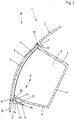
- a dashboard 1 intended for a motor vehicle and made of plastic comprises a passenger airbag a front part 2 with an opening 3 and an airbag compartment 4 (pocket-shaped recess), which serves to receive an airbag module, not shown in the figures.
- a cover element 5 is used to cover the airbag compartment 4 and to close the opening 3 in the front part 2.
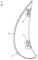
- the cover element 5 is arranged, for example, flush in the front part 2 of the dashboard 1 and lies in a suitable recess 6. This can be seen schematically and in section from FIG. 1.
- wall pieces 7, 8 and a bottom 9 are provided. Together they form a compartment, the contour of which is congruent or almost congruent with the contour 10 of the cover element 5 according to FIG. 2.
- the wall pieces 7 and 8 each merge into the front part 2 with a shoulder 11 and 12 forming a projection.
- edge parts 13 and 14 are provided, on which the cover element 5 with edge elements 15 and 16 also lies in the assembled state according to FIG. 1.
- the edge elements 15 and 16 projecting towards the bottom 9 are arranged all around and form a common edge element.
- At least one clip-art fastening element 17, which latches with the front part 2, is provided.
- This fastening element 17 is arranged on the cover element 5, which can preferably be in one piece.
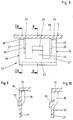
- the fastening element 17 comprises two holding fingers 18 and 19 arranged at a distance from one another, a web 21 connecting their free ends 20 and a locking finger 22 with a locking lug 23 extending parallel to and between the holding fingers 18, 19 , which is assigned a locking surface 24 on the dashboard 1 or on its front part 2.
- this latching surface 24 is specifically a surface on the shoulder 12 facing away from the cover element 5, which is located between the wall piece 8 of the airbag compartment 4 and a part 2a of the front part 2.
- edge part 14 belonging to the paragraph 12 has a passage opening 25 for each fastening element 17.
- the fastening element 17 can be pushed with its web-side end 26 through the passage opening 25 until the locking lug 23 bears against the locking surface 24 behind the shoulder 12 (FIGS. 1 and 7).
- the cover element 5 simultaneously reaches the desired installation position according to FIG. 1.
- the cross section of the two holding fingers 18, 19 is approximately L-shaped according to the exemplary embodiment shown in FIGS. 1 to 10. They each consist of a leg 27 which extends in the sheet plane in FIGS. 3 and 8 and a leg 28 which extends perpendicularly thereto.
- the fastening element 17 is attached to the cover element 5 directly at predetermined breaking points 30, 31 and 32, 33. These predetermined breaking points 30 to 33 are predetermined breaking lines due to their length.
- the two predetermined breaking lines 30 and 33 connect the two legs 27 of the two holding fingers 18, 19 to the cover element 5 and the two predetermined breaking lines 31 and 32 connect the other two legs 28 of the two retaining fingers 18, 19 to the cover element 5.
- the detent finger 21 of the fastening element 17 extends with its free end, which carries the detent 23, from the web 21 to the cover element 5, as can also be seen from a comparison of FIGS. 1 and 3 or 7, 8.
- FIGS. 5 and 6 show the situation after the cover element 5 has been released from the fastening element 17.
- the holding fingers 18 and 19 lie at least with their legs 18 in the X direction according to FIG. 3 and / or in the Y direction according to FIG 7 positively in the passage opening (s) 25.
- the holding fingers 18, 19 guide the fastening element 17, the latching finger 22 initially dodging with its latching lug 23, for which purpose a ramp slope 23a according to FIG. 7 is provided on the underside of the latching finger 22. Only when the locking lug 23 has reached the space behind the shoulder 12 does it lie on the locking surface 24, as shown in FIG. 7. The cover element 5 is secured from this moment on.
- FIGS. 4 and 5 finally show that an attachment 34 can be arranged on the cover element 5, which serves directly as a carrier for the fastening element 17 or on which the fastening element 17 with its predetermined breaking points 30 to 33 is arranged.
- the two FIGS. 5 and 6 also show the situation after the break in the area of the predetermined breaking points 30 to 33.
- FIGS. 8 to 10 also clearly show the position of the predetermined breaking points or predetermined breaking lines 30 to 33 on the respective legs 27 and 28 of the holding fingers 18 and 19.
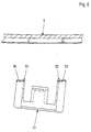
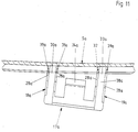
- FIG. 11 shows a slightly modified embodiment of a fastening element 17a. It differs from the exemplary embodiment described first only in that the holding fingers 18a and 19a are not L-shaped in cross section, but rather U-shaped. They each have a web 38a and two legs 28a instead of a single leg 28 which extends in the Y direction, in accordance with the exemplary embodiment described first. Correspondingly, a further predetermined breaking point or predetermined breaking line 39a is provided on each holding finger 18a or 19a, as can be seen from FIG. 11.
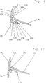
- FIGS. 12 and 13 Another embodiment is shown in FIGS. 12 and 13 and has the same reference numbers with the different letter index b for matching parts.
- FIGS. 12 and 13 While the fastening element 17 or 17a used to fasten the cover element 5 to the front part 2 is connected in one piece to the cover element 5 or 5a in the exemplary embodiments illustrated in FIGS. 1 to 11, the embodiment according to FIGS. 12 and 13 relates to a fastening element 17b, which is a separate part and in turn is fixed to the cover element 5b as shown in FIG. 12. At least one holding element 40b, which e.g. a passage opening 41b extends through and engages behind the fastening element 17b and thereby gives the fastening element 17b a secure and firm hold on the cover element 5b.
- a holding element 40b which e.g. a passage opening 41b extends through and engages behind the fastening element 17b and thereby gives the fastening element 17b a secure and firm hold on the cover element 5b.
- the passage opening 41b is located in a leg 42b which bears against the inside of the cover element 5b.
- the holding element 40b is mushroom-shaped and engages behind the leg 42b with its head 43b. It is particularly expedient if the holding element 40b is connected in one piece to the cover element 5b.
- the holding element 40b has a predetermined breaking point 44b, which breaks when the airbag of the airbag module fills and pushes the cover element 5b away.
- the predetermined breaking point or predetermined breaking line 44b provided on the holding element 40b is located at a location that is difficult to access and in particular, according to the exemplary embodiment, inside the through opening 41b of the leg 42b of the cover Holding element 17b. It is preferably arranged on the stem-like intermediate piece 45b, which connects the head 43b to the cover element 5b.
Landscapes
- Engineering & Computer Science (AREA)
- Mechanical Engineering (AREA)
- Air Bags (AREA)
Applications Claiming Priority (2)
| Application Number | Priority Date | Filing Date | Title |
|---|---|---|---|
| DE4310636 | 1993-04-01 | ||
| DE4310636A DE4310636A1 (de) | 1993-04-01 | 1993-04-01 | Armaturentafel mit Beifahrer-Airbag |
Publications (2)
| Publication Number | Publication Date |
|---|---|
| EP0618110A1 true EP0618110A1 (fr) | 1994-10-05 |
| EP0618110B1 EP0618110B1 (fr) | 1996-12-18 |
Family
ID=6484426
Family Applications (1)
| Application Number | Title | Priority Date | Filing Date |
|---|---|---|---|
| EP94103737A Expired - Lifetime EP0618110B1 (fr) | 1993-04-01 | 1994-03-11 | Tableau de bord avec air-bag pour passager |
Country Status (3)
| Country | Link |
|---|---|
| EP (1) | EP0618110B1 (fr) |
| DE (2) | DE4310636A1 (fr) |
| ES (1) | ES2096362T3 (fr) |
Cited By (8)
| Publication number | Priority date | Publication date | Assignee | Title |
|---|---|---|---|---|
| EP0695670A1 (fr) * | 1994-08-05 | 1996-02-07 | Morton International, Inc. | Système de fixation frangible pour couvercles de déploiement de sacs gonflables |
| US5580081A (en) * | 1994-06-22 | 1996-12-03 | Deutsche Fibrit Gesellschaft Ebers & Dr. Muller Mbh | Dashboard having an integral air bag discharge channel |
| EP0743230A3 (fr) * | 1995-05-16 | 1997-04-09 | Morton Int Inc | Système de fixation frangible pour des couvercles de déploiement de sac gonflable |
| WO1998008714A1 (fr) * | 1996-08-26 | 1998-03-05 | The Goodyear Tire And Rubber Company | Porte a coussin d'air de tableau de bord cote passager |
| GB2328646A (en) * | 1997-04-17 | 1999-03-03 | Alliedsignal Deutschland Gmbh | Airbag cover attachment |
| EP0792773B2 (fr) † | 1996-02-27 | 2002-10-16 | TAKATA-PETRI (Ulm) GmbH | Module pour coussin d'air à boítier constitué d'une multitude de pièces détachables |
| GB2388342A (en) * | 2002-05-06 | 2003-11-12 | Lear Corp | Instrument panel with integrally moulded air bag canister |
| EP3219556A1 (fr) * | 2016-03-14 | 2017-09-20 | Hyundai Motor Company | Tableau de bord d'auto intégré et son procédé de fabrication |
Families Citing this family (3)
| Publication number | Priority date | Publication date | Assignee | Title |
|---|---|---|---|---|
| DE19505214C2 (de) * | 1995-02-16 | 2000-05-04 | Johnson Contr Interiors Gmbh | Innenverkleidungsteil für eine Seitentür eines Personenkraftwagens |
| DE19507038C1 (de) * | 1995-03-01 | 1996-04-25 | Ymos Ag Ind Produkte | Abdeckung für die Öffnung einer Airbag-Kammer und Vorrichtung zur zerstörungsfreien Entfernung der Abdeckung |
| DE10141943B4 (de) * | 2001-08-28 | 2004-09-23 | Bayerische Motoren Werke Ag | Türairbaganordnung für Fahrzeuge |
Citations (6)
| Publication number | Priority date | Publication date | Assignee | Title |
|---|---|---|---|---|
| DE3433941A1 (de) * | 1984-09-15 | 1986-03-27 | Bayerische Motoren Werke AG, 8000 München | Kraftfahrzeuglenkrad |
| DE3545028A1 (de) * | 1985-12-19 | 1987-07-02 | Audi Ag | Abdeckkappe |
| EP0235383A1 (fr) * | 1986-02-21 | 1987-09-09 | Dr.Ing.h.c. F. Porsche Aktiengesellschaft | Dispositif de protection contre les chocs pour les occupants d'un véhicule automobile |
| EP0367319A2 (fr) * | 1988-11-01 | 1990-05-09 | KOLBENSCHMIDT Aktiengesellschaft | Dispositif de protection par sac d'air en cas d'accident |
| EP0415362A2 (fr) * | 1989-08-30 | 1991-03-06 | Mazda Motor Corporation | Dispositif de coussin d'air pour véhicule |
| DE4139010A1 (de) * | 1990-11-27 | 1992-06-04 | Nissan Motor | Air-bag-einrichtung |
Family Cites Families (1)
| Publication number | Priority date | Publication date | Assignee | Title |
|---|---|---|---|---|
| US4893833A (en) * | 1988-09-08 | 1990-01-16 | Tip Engineering Group, Inc. | Closure for an air bag deployment opening |
-
1993
- 1993-04-01 DE DE4310636A patent/DE4310636A1/de not_active Withdrawn
-
1994
- 1994-03-11 DE DE59401294T patent/DE59401294D1/de not_active Expired - Fee Related
- 1994-03-11 ES ES94103737T patent/ES2096362T3/es not_active Expired - Lifetime
- 1994-03-11 EP EP94103737A patent/EP0618110B1/fr not_active Expired - Lifetime
Patent Citations (6)
| Publication number | Priority date | Publication date | Assignee | Title |
|---|---|---|---|---|
| DE3433941A1 (de) * | 1984-09-15 | 1986-03-27 | Bayerische Motoren Werke AG, 8000 München | Kraftfahrzeuglenkrad |
| DE3545028A1 (de) * | 1985-12-19 | 1987-07-02 | Audi Ag | Abdeckkappe |
| EP0235383A1 (fr) * | 1986-02-21 | 1987-09-09 | Dr.Ing.h.c. F. Porsche Aktiengesellschaft | Dispositif de protection contre les chocs pour les occupants d'un véhicule automobile |
| EP0367319A2 (fr) * | 1988-11-01 | 1990-05-09 | KOLBENSCHMIDT Aktiengesellschaft | Dispositif de protection par sac d'air en cas d'accident |
| EP0415362A2 (fr) * | 1989-08-30 | 1991-03-06 | Mazda Motor Corporation | Dispositif de coussin d'air pour véhicule |
| DE4139010A1 (de) * | 1990-11-27 | 1992-06-04 | Nissan Motor | Air-bag-einrichtung |
Cited By (11)
| Publication number | Priority date | Publication date | Assignee | Title |
|---|---|---|---|---|
| US5580081A (en) * | 1994-06-22 | 1996-12-03 | Deutsche Fibrit Gesellschaft Ebers & Dr. Muller Mbh | Dashboard having an integral air bag discharge channel |
| EP0695670A1 (fr) * | 1994-08-05 | 1996-02-07 | Morton International, Inc. | Système de fixation frangible pour couvercles de déploiement de sacs gonflables |
| EP0743230A3 (fr) * | 1995-05-16 | 1997-04-09 | Morton Int Inc | Système de fixation frangible pour des couvercles de déploiement de sac gonflable |
| EP0792773B2 (fr) † | 1996-02-27 | 2002-10-16 | TAKATA-PETRI (Ulm) GmbH | Module pour coussin d'air à boítier constitué d'une multitude de pièces détachables |
| WO1998008714A1 (fr) * | 1996-08-26 | 1998-03-05 | The Goodyear Tire And Rubber Company | Porte a coussin d'air de tableau de bord cote passager |
| GB2328646A (en) * | 1997-04-17 | 1999-03-03 | Alliedsignal Deutschland Gmbh | Airbag cover attachment |
| EP0881129A3 (fr) * | 1997-04-17 | 1999-07-14 | Breed Automotive Technology, Inc. | Moyen de fixation d'un couvercle de sac de sécurité gonflable |
| GB2328646B (en) * | 1997-04-17 | 2001-06-06 | Alliedsignal Deutschland Gmbh | Airbag cover attachment |
| GB2388342A (en) * | 2002-05-06 | 2003-11-12 | Lear Corp | Instrument panel with integrally moulded air bag canister |
| GB2388342B (en) * | 2002-05-06 | 2004-12-01 | Lear Corp | Air bag containment apparatus |
| EP3219556A1 (fr) * | 2016-03-14 | 2017-09-20 | Hyundai Motor Company | Tableau de bord d'auto intégré et son procédé de fabrication |
Also Published As
| Publication number | Publication date |
|---|---|
| EP0618110B1 (fr) | 1996-12-18 |
| DE59401294D1 (de) | 1997-01-30 |
| DE4310636A1 (de) | 1994-10-06 |
| ES2096362T3 (es) | 1997-03-01 |
Similar Documents
| Publication | Publication Date | Title |
|---|---|---|
| DE69020071T2 (de) | Gassack-Vorrichtung für ein Kraftfahrzeug. | |
| EP1037772B1 (fr) | Coussin gonflable pour module d'airbag | |
| DE69805568T2 (de) | Luftsack-Gehäuseeinrichtung | |
| EP0461276B1 (fr) | Dispositif de sécurité de retenue par sac à air dans des véhicules automobiles | |
| EP1165350B1 (fr) | Ensemble ceinture de securite avec derouleurs automatiques individuels de ceinture au niveau des epaules et au niveau du bassin | |
| DE69605690T2 (de) | Lösbarer Befestigungszusammenbau | |
| DE10108685C1 (de) | Halter für ein Innenverkleidungsteil eines Fahrzeugs | |
| DE4306449A1 (fr) | ||
| EP3650290A1 (fr) | Module de sac gonflage, son procédé de montage ainsi que module de direction doté d'un tel module de sac gonflage | |
| EP0618110A1 (fr) | Tableau de bord avec air-bag pour passager | |
| DE19621397B4 (de) | Airbagmodul | |
| DE10041763B4 (de) | Airbag-Befestigung | |
| EP0980797A2 (fr) | Module de sac de sécurité gonflable | |
| EP1147949B1 (fr) | Module de sac de sécurité gonflable | |
| DE10001040C1 (de) | Instrumententafel für ein Kraftfahrzeug mit integrierter Airbag-Abdeckung | |
| DE102012011982A1 (de) | Gassackabdeckung mit einem Emblem und Verfahren zu ihrer Herstellung | |
| DE202023107128U1 (de) | Sicherheitssystem für ein Fahrzeug | |
| EP3250420B1 (fr) | Dispositif de coussin gonflable pour vehicule automobile | |
| DE10122071A1 (de) | Abdeckung für ein Gassack-Modul | |
| DE102018205809B4 (de) | Trägerelement zum Befestigen eines Innenverkleidungsteils an einem Bauteil eines Fahrzeugs. | |
| DE29801871U1 (de) | Gassack-Modul für einen Kopfschutz-Gassack | |
| DE102020120774A1 (de) | Befestigungsvorrichtung für eine fahrzeuginnenverkleidung, anordnung einer befestigungsvorrichtung, gassackmodul und verfahren zum öffnen eines gassacks | |
| DE102020002900A1 (de) | Gurtbandführungselement | |
| EP1356990B1 (fr) | Dispositif de protection pour véhicule automobile comme couvercle pour compartiment à bagages, filet de séparation ou similaire | |
| DE102009056211B4 (de) | Gassackmodul |
Legal Events
| Date | Code | Title | Description |
|---|---|---|---|
| PUAI | Public reference made under article 153(3) epc to a published international application that has entered the european phase |
Free format text: ORIGINAL CODE: 0009012 |
|
| AK | Designated contracting states |
Kind code of ref document: A1 Designated state(s): DE ES FR GB IT |
|
| 17P | Request for examination filed |
Effective date: 19940902 |
|
| 17Q | First examination report despatched |
Effective date: 19950802 |
|
| GRAG | Despatch of communication of intention to grant |
Free format text: ORIGINAL CODE: EPIDOS AGRA |
|
| GRAH | Despatch of communication of intention to grant a patent |
Free format text: ORIGINAL CODE: EPIDOS IGRA |
|
| GRAH | Despatch of communication of intention to grant a patent |
Free format text: ORIGINAL CODE: EPIDOS IGRA |
|
| GRAA | (expected) grant |
Free format text: ORIGINAL CODE: 0009210 |
|
| AK | Designated contracting states |
Kind code of ref document: B1 Designated state(s): DE ES FR GB IT |
|
| REF | Corresponds to: |
Ref document number: 59401294 Country of ref document: DE Date of ref document: 19970130 |
|
| ET | Fr: translation filed | ||
| GBT | Gb: translation of ep patent filed (gb section 77(6)(a)/1977) |
Effective date: 19970127 |
|
| PGFP | Annual fee paid to national office [announced via postgrant information from national office to epo] |
Ref country code: FR Payment date: 19970225 Year of fee payment: 4 |
|
| REG | Reference to a national code |
Ref country code: ES Ref legal event code: FG2A Ref document number: 2096362 Country of ref document: ES Kind code of ref document: T3 |
|
| ITF | It: translation for a ep patent filed | ||
| PGFP | Annual fee paid to national office [announced via postgrant information from national office to epo] |
Ref country code: ES Payment date: 19970320 Year of fee payment: 4 |
|
| PLBE | No opposition filed within time limit |
Free format text: ORIGINAL CODE: 0009261 |
|
| STAA | Information on the status of an ep patent application or granted ep patent |
Free format text: STATUS: NO OPPOSITION FILED WITHIN TIME LIMIT |
|
| 26N | No opposition filed | ||
| PG25 | Lapsed in a contracting state [announced via postgrant information from national office to epo] |
Ref country code: GB Free format text: LAPSE BECAUSE OF NON-PAYMENT OF DUE FEES Effective date: 19980311 |
|
| PG25 | Lapsed in a contracting state [announced via postgrant information from national office to epo] |
Ref country code: ES Free format text: LAPSE BECAUSE OF NON-PAYMENT OF DUE FEES Effective date: 19980312 |
|
| PG25 | Lapsed in a contracting state [announced via postgrant information from national office to epo] |
Ref country code: FR Free format text: THE PATENT HAS BEEN ANNULLED BY A DECISION OF A NATIONAL AUTHORITY Effective date: 19980331 |
|
| GBPC | Gb: european patent ceased through non-payment of renewal fee |
Effective date: 19980311 |
|
| REG | Reference to a national code |
Ref country code: FR Ref legal event code: ST |
|
| REG | Reference to a national code |
Ref country code: ES Ref legal event code: FD2A Effective date: 20000503 |
|
| PGFP | Annual fee paid to national office [announced via postgrant information from national office to epo] |
Ref country code: DE Payment date: 20020309 Year of fee payment: 9 |
|
| PG25 | Lapsed in a contracting state [announced via postgrant information from national office to epo] |
Ref country code: DE Free format text: LAPSE BECAUSE OF NON-PAYMENT OF DUE FEES Effective date: 20031001 |
|
| PG25 | Lapsed in a contracting state [announced via postgrant information from national office to epo] |
Ref country code: IT Free format text: LAPSE BECAUSE OF NON-PAYMENT OF DUE FEES;WARNING: LAPSES OF ITALIAN PATENTS WITH EFFECTIVE DATE BEFORE 2007 MAY HAVE OCCURRED AT ANY TIME BEFORE 2007. THE CORRECT EFFECTIVE DATE MAY BE DIFFERENT FROM THE ONE RECORDED. Effective date: 20050311 |