EP0618111B1 - Tendeur de ceinture pour système de ceinture de sécurité pour véhicule - Google Patents
Tendeur de ceinture pour système de ceinture de sécurité pour véhicule Download PDFInfo
- Publication number
- EP0618111B1 EP0618111B1 EP94104182A EP94104182A EP0618111B1 EP 0618111 B1 EP0618111 B1 EP 0618111B1 EP 94104182 A EP94104182 A EP 94104182A EP 94104182 A EP94104182 A EP 94104182A EP 0618111 B1 EP0618111 B1 EP 0618111B1
- Authority
- EP
- European Patent Office
- Prior art keywords
- piston
- wall surface
- cylinder
- belt
- limiting wall
- Prior art date
- Legal status (The legal status is an assumption and is not a legal conclusion. Google has not performed a legal analysis and makes no representation as to the accuracy of the status listed.)
- Expired - Lifetime
Links
- 238000000034 method Methods 0.000 description 4
- 239000007789 gas Substances 0.000 description 3
- 238000004519 manufacturing process Methods 0.000 description 2
- 238000007789 sealing Methods 0.000 description 2
- 230000000694 effects Effects 0.000 description 1
- 230000008030 elimination Effects 0.000 description 1
- 238000003379 elimination reaction Methods 0.000 description 1
- 230000000717 retained effect Effects 0.000 description 1
- 239000000565 sealant Substances 0.000 description 1
Images
Classifications
-
- B—PERFORMING OPERATIONS; TRANSPORTING
- B60—VEHICLES IN GENERAL
- B60R—VEHICLES, VEHICLE FITTINGS, OR VEHICLE PARTS, NOT OTHERWISE PROVIDED FOR
- B60R22/00—Safety belts or body harnesses in vehicles
- B60R22/18—Anchoring devices
- B60R22/195—Anchoring devices with means to tension the belt in an emergency, e.g. means of the through-anchor or splitted reel type
- B60R22/1952—Transmission of tensioning power by cable; Return motion locking means therefor
-
- Y—GENERAL TAGGING OF NEW TECHNOLOGICAL DEVELOPMENTS; GENERAL TAGGING OF CROSS-SECTIONAL TECHNOLOGIES SPANNING OVER SEVERAL SECTIONS OF THE IPC; TECHNICAL SUBJECTS COVERED BY FORMER USPC CROSS-REFERENCE ART COLLECTIONS [XRACs] AND DIGESTS
- Y10—TECHNICAL SUBJECTS COVERED BY FORMER USPC
- Y10T—TECHNICAL SUBJECTS COVERED BY FORMER US CLASSIFICATION
- Y10T74/00—Machine element or mechanism
- Y10T74/20—Control lever and linkage systems
- Y10T74/20396—Hand operated
- Y10T74/20402—Flexible transmitter [e.g., Bowden cable]
- Y10T74/20462—Specific cable connector or guide
Definitions
- the invention relates to a belt tensioner in a vehicle seat belt system, with a piston / cylinder arrangement, a traction cable which is connected on the one hand to the belt buckle and on the other hand to the piston which is displaceably mounted in the cylinder, and a backstop which prevents movement of the piston against the direction of tension .
- Belt tensioners are known in different embodiments.
- a mechanical belt tensioner is disclosed in the generic DE 89 00 013.7 U1, which has two axially displaceable pistons in a cylinder.
- a disk-shaped locking element is arranged between the pistons attached to the traction cable, through which the traction cable is guided.
- the piston near the belt buckle is bevelled on its side facing the other piston, and the locking element has at least approximately the same elliptical shape and dimension that is formed by the beveling of the piston near the belt buckle.
- the piston With the reversal of movement of the piston, the piston, which is remote from the buckle, pushes the locking element in the direction of a position perpendicular to the traction cable, as a result of which the locking element is pressed against the wall of the cylinder and is pressed into it at high forces. The locking element is thus blocked against further movement of the piston against the direction of the penalty. In this way, a backstop for the piston / cylinder arrangement is formed.
- the invention has for its object to develop a belt tensioner of the type specified in such a way that with simple manufacture and assembly only a short path of the piston is required to activate the backstop.
- a belt tensioner of the type mentioned at the outset in that the piston has a circumferential groove in which two half-ring disks are arranged in an opposite oblique position to the axis of the piston and are supported on one another with the circumferential ends and on their outer circumference with the wall of the cylinder in Are kept in touch.
- This training according to the invention is characterized by structural simplicity and low manufacturing costs.
- the arrangement of the two half-ring disks creates a so-called toggle effect, i.e. the two half-ring washers are pivotally supported at their ends and, when the piston reverses after the tensioning process, are erected with only a very small control movement from their inclined position and penetrate into the wall of the cylinder.
- This has the advantage that the backstop is activated immediately when the piston reverses its movement, the piston is blocked and the elimination of the belt slack caused by the belt tensioning process is essentially retained.
- the circumferential ends of the half-ring disks are pivotably supported on a radial boundary wall of the circumferential groove. It is particularly advantageous that the boundary wall of the circumferential groove opposite the radial boundary wall is inclined obliquely to the axis of the piston. The two half-ring disks are pressed evenly against the obliquely inclined boundary wall when the piston is accelerated for the pretensioning process if the inclination of the boundary wall corresponds in each case to the inclination which the half-ring disks assume in their opposite oblique position to the axis of the piston.
- the backstop can also be used in a piston that is part of a piston / cylinder linear drive of the belt tensioner.
- the obliquely inclined boundary wall is provided on its outer circumference with a circumferential step, in which an O-ring is arranged, which is in contact with the wall of the cylinder on its outer circumference and on whose side facing the radial boundary wall, the half-washers are supported in the axial direction .
- the O-sealing ring acts both as a sealant for the gases acting on the piston for the pretensioning process and as a spring element that prestresses the half-ring disks against the cylinder wall.
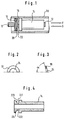
- a piston 14 is arranged on a traction cable 12, which has an O-ring 16 and two half-ring disks 18 and 20 in an annular circumferential groove 22.
- the piston 14 is slidably guided in the tubular cylinder 10.
- the cylinder 10 is, for example, anchored to the vehicle in a seat belt system and part of a piston / cylinder linear drive, and a belt buckle, not shown here, is connected to the traction cable 12.
- the circumferential groove 22 has a radial boundary wall 221 in the direction of tightening F. This is followed by a cylindrical surface 222. In the direction G, that is to say opposite to the direction of tension F, the circumferential groove 22 has a boundary wall 223 which is inclined obliquely to the axis of the piston 14.
- the half-ring disks 18 and 20 are in the opposite oblique position to the axis of the piston 14 and with the circumferential ends pivotable on each other and arranged on the boundary wall 221 supporting. By means of the boundary wall 223, the half ring disks 18 and 20 are held in a rest position inclined to the axis of the cylinder 10 at an angle ⁇ of approximately 60 ° (FIG. 3).
- a circumferential step 224 is provided on the outer circumference of the boundary wall 223.
- the O-sealing ring 16 is arranged in this circumferential step 224.
- the O-ring 16 is in contact with the wall of the cylinder on its outer circumference.
- the half-ring disks 18 and 20 are supported in the axial direction.
- the front area of the piston 14 has a smaller diameter than the rear area and is pressed with the traction cable 12.
- the piston / cylinder arrangement shown in Fig. 1 forms the linear drive of the belt tensioner acting on the belt buckle.
- the piston 14 in the cylinder 10 is subjected to the pressure of the gases generated by a pyrotechnic gas generator, so that the piston 14 in Fig. 1 is moved in the direction of arrow F in the cylinder 10, the traction cable 12 and consequently the belt buckle connected thereto get picked up.
- the half-ring disks 18 and 20 remain in their inclined position.
- the forward movement of the vehicle occupant secured by the belt system begins, with a pull being exerted on the piston 14 in the direction of arrow G in FIG.
- the half-ring disks 18 and 20 straighten up and press on one side against the wall of the cylinder 10 and on the other side with the pivoting increasingly against one another.
- the piston 14 is then locked in the G direction.
Landscapes
- Engineering & Computer Science (AREA)
- Mechanical Engineering (AREA)
- Automotive Seat Belt Assembly (AREA)
- Pulleys (AREA)
- Devices For Conveying Motion By Means Of Endless Flexible Members (AREA)
Claims (5)
- Tendeur de ceinture dans un système de ceinture de sécurité pour véhicule, comprenant un agencement à piston-cylindre (10, 14), un câble de traction (12), qui est relié d'une part à la serrure de la ceinture et d'autre part au piston (14) monté coulissant dans le cylindre (10), et un dispositif anti-retour (16, 18, 20, 22) qui interdit un déplacement du piston (14) en sens opposé au sens de tension (F), caractérisé en ce que le piston (14) comporte une rainure périphérique (22), dans laquelle deux demi-rondelles (18, 20) sont disposées dans des positions inclinées opposées par rapport à l'axe du piston (14) et en prenant appui l'une contre l'autre par leurs extrémités périphériques et sont maintenues en contact, au niveau de leur périphérie extérieure, avec la paroi du cylindre (10).
- Tendeur de ceinture selon la revendication 1, caractérisé en ce que les extrémités périphériques des demi-rondelles (18, 20) prennent appui de manière pivotante sur une paroi radiale de délimitation (221) de la rainure périphérique (22).
- Tendeur de ceinture selon la revendication 2, caractérisé en ce que la paroi de délimitation (223) qui appartient à la rainure périphérique (22) et qui est située en vis-à-vis de la paroi radiale de délimitation (221) est inclinée par rapport à l'axe du piston (14).
- Tendeur de ceinture selon la revendication 3, caractérisé en ce que l'inclinaison de la paroi de délimitation (223) correspond à l'inclinaison que les demi-rondelles (18, 20) adoptent lorsqu'elles se trouvent en position inclinée opposée par rapport à l'axe du piston (14).
- Tendeur de ceinture selon la revendication 3 ou 4, caractérisé en ce que la paroi de délimitation inclinée (223) comporte, à sa périphérie extérieure, un gradin périphérique (224) dans lequel est disposé un joint torique d'étanchéité (16) qui, à sa périphérie extérieure, est en contact avec la paroi du cylindre (10) et sur le côté duquel, ledit côté étant tourné vers la paroi radiale de délimitation (221), les demi-rondelles (18, 20) prennent appui dans le sens axial.
Applications Claiming Priority (2)
| Application Number | Priority Date | Filing Date | Title |
|---|---|---|---|
| DE9305086U | 1993-04-02 | ||
| DE9305086U DE9305086U1 (de) | 1993-04-02 | 1993-04-02 | Gurtstraffer für ein Fahrzeugsicherheitsgurtsystem |
Publications (2)
| Publication Number | Publication Date |
|---|---|
| EP0618111A1 EP0618111A1 (fr) | 1994-10-05 |
| EP0618111B1 true EP0618111B1 (fr) | 1996-06-19 |
Family
ID=6891604
Family Applications (1)
| Application Number | Title | Priority Date | Filing Date |
|---|---|---|---|
| EP94104182A Expired - Lifetime EP0618111B1 (fr) | 1993-04-02 | 1994-03-17 | Tendeur de ceinture pour système de ceinture de sécurité pour véhicule |
Country Status (5)
| Country | Link |
|---|---|
| US (1) | US5481940A (fr) |
| EP (1) | EP0618111B1 (fr) |
| JP (1) | JP2507232B2 (fr) |
| DE (2) | DE9305086U1 (fr) |
| ES (1) | ES2062966T3 (fr) |
Families Citing this family (9)
| Publication number | Priority date | Publication date | Assignee | Title |
|---|---|---|---|---|
| DE9312135U1 (de) * | 1993-08-13 | 1994-06-01 | Leicher Gmbh & Co, 85551 Kirchheim | Gurtstraffer |
| DE29616414U1 (de) * | 1996-09-20 | 1997-01-23 | Trw Occupant Restraint Systems Gmbh, 73551 Alfdorf | Gurtstraffer |
| US6145881A (en) * | 1999-01-15 | 2000-11-14 | Breed Automotive Technology Inc. | Seatback mounted seat belt tensioner |
| JP2002362311A (ja) * | 2001-06-12 | 2002-12-18 | Honda Motor Co Ltd | 自動車の車体構造 |
| JP4621384B2 (ja) | 2001-07-18 | 2011-01-26 | 本田技研工業株式会社 | 乗員保護装置 |
| JP4448626B2 (ja) * | 2001-07-18 | 2010-04-14 | 本田技研工業株式会社 | 乗員保護装置 |
| JP4656556B2 (ja) * | 2001-08-10 | 2011-03-23 | タカタ株式会社 | プリテンショナー |
| DE102005031896A1 (de) * | 2005-07-07 | 2007-04-19 | Siemens Ag | Haltebremsvorrichtung |
| US8770506B2 (en) | 2010-07-06 | 2014-07-08 | Autoliv Asp, Inc. | High seal retractor pretensioner piston |
Family Cites Families (9)
| Publication number | Priority date | Publication date | Assignee | Title |
|---|---|---|---|---|
| US3239273A (en) * | 1964-06-19 | 1966-03-08 | Lennord L Pitney | Lap belt tightener |
| DE2253657C2 (de) * | 1972-11-02 | 1984-09-06 | Dynamit Nobel Ag, 5210 Troisdorf | Vorrichtung zum Spannen von Sicherheitsgurten in Fahrzeugen |
| US4091621A (en) * | 1975-06-02 | 1978-05-30 | Networks Electronic Corp. | Pyrotechnic piston actuator |
| DE2624942C2 (de) * | 1976-06-03 | 1985-12-12 | Boge Gmbh, 5208 Eitorf | Vorrichtung zum Spannen und gesteuerten Wiedernachgeben von Sicherheitsgurten |
| DE2809587A1 (de) * | 1977-03-09 | 1978-09-14 | Britax Wingard Ltd | Spannvorrichtung fuer einen sicherheitsgurt |
| JPS5825156U (ja) * | 1981-08-12 | 1983-02-17 | トヨタ自動車株式会社 | シ−トベルト引締め装置 |
| DE8900013U1 (de) * | 1989-01-02 | 1989-02-16 | R. Schmidt GmbH, 5940 Lennestadt | Sperrvorrichtung für mechanischen Sicherheitsgurtstrammer |
| JPH0450058A (ja) * | 1990-06-18 | 1992-02-19 | Takata Kk | シートベルト装置のプリテンショナー |
| DE4206093C1 (fr) * | 1992-02-27 | 1993-07-15 | Trw Repa Gmbh, 7077 Alfdorf, De |
-
1993
- 1993-04-02 DE DE9305086U patent/DE9305086U1/de not_active Expired - Lifetime
-
1994
- 1994-03-17 DE DE59400364T patent/DE59400364D1/de not_active Expired - Fee Related
- 1994-03-17 ES ES94104182T patent/ES2062966T3/es not_active Expired - Lifetime
- 1994-03-17 EP EP94104182A patent/EP0618111B1/fr not_active Expired - Lifetime
- 1994-03-29 US US08/219,942 patent/US5481940A/en not_active Expired - Fee Related
- 1994-04-01 JP JP6064849A patent/JP2507232B2/ja not_active Expired - Lifetime
Also Published As
| Publication number | Publication date |
|---|---|
| DE9305086U1 (de) | 1993-05-27 |
| US5481940A (en) | 1996-01-09 |
| JP2507232B2 (ja) | 1996-06-12 |
| ES2062966T3 (es) | 1996-10-16 |
| DE59400364D1 (de) | 1996-07-25 |
| JPH06321054A (ja) | 1994-11-22 |
| ES2062966T1 (es) | 1995-01-01 |
| EP0618111A1 (fr) | 1994-10-05 |
Similar Documents
| Publication | Publication Date | Title |
|---|---|---|
| EP0562423B1 (fr) | Enrouleur de ceinture muni d'un tendeur opérant sur la bobine | |
| EP0806327B1 (fr) | Dispositif d'entraínement linéaire pour un système de retenue des occupants d'un véhicule | |
| DE3407378A1 (de) | Sicherheitsgurtaufroller mit strammvorrichtung | |
| EP0808752B1 (fr) | Tendeur de ceinture d'un dispositif de retenue des passagers d'un véhicule | |
| EP0618111B1 (fr) | Tendeur de ceinture pour système de ceinture de sécurité pour véhicule | |
| DE19602549A1 (de) | Massekörperantrieb für einen Rotationsstraffer | |
| DE19518130C2 (de) | Sicherheitslenksäule eines Kraftfahrzeuges | |
| DE2505624A1 (de) | Spannvorrichtung fuer einen sicherheitsgurt von fahrzeugen, insbesondere kraftfahrzeugen | |
| DE2330635B2 (de) | Durch eine Treibladung betätigte Einstellvorrichtung | |
| DE8314221U1 (de) | Spannvorrichtung zur Befestigung von Maschinenteilen | |
| DE102006039476A1 (de) | Lenksäulenanordnung | |
| DE3933721A1 (de) | Kraftbegrenzer fuer sicherheitsgurt-rueckhaltesysteme | |
| EP0518091B1 (fr) | Arbre de direction télescopique pour véhicule automobile | |
| EP0844153B1 (fr) | Rétracteur de boucle | |
| DE2726096A1 (de) | Spannvorrichtung fuer sicherheitsgurte | |
| DE3400177A1 (de) | Vorrichtung zur strammung von sicherheitsgurten | |
| EP0846908A1 (fr) | Connection entre tube et composant. | |
| DE19605956A1 (de) | Kraftstoffeinspritzventil für Brennkraftmaschinen | |
| DE3407379C2 (fr) | ||
| DE102005058545B3 (de) | Seilstraffer mit einer Seilabdichtung | |
| DE20111638U1 (de) | Linearstrafferantrieb zum Straffen eines Fahrzeugsicherheitsgurtes | |
| DE8330933U1 (de) | Vorrichtung zur Sicherung von Kraftfahrzeugen gegen Diebstahl | |
| DE29811538U1 (de) | Gurtstraffer | |
| DE69710402T2 (de) | Vereinfachtes Insassen- Airbagmodul, das den Gasgenerator als Strukurelement benutzt | |
| DE29818655U1 (de) | Schloßstraffer |
Legal Events
| Date | Code | Title | Description |
|---|---|---|---|
| PUAI | Public reference made under article 153(3) epc to a published international application that has entered the european phase |
Free format text: ORIGINAL CODE: 0009012 |
|
| AK | Designated contracting states |
Kind code of ref document: A1 Designated state(s): DE ES FR GB IT SE |
|
| ITCL | It: translation for ep claims filed |
Representative=s name: DR. ING. A. RACHELI & C. |
|
| GBC | Gb: translation of claims filed (gb section 78(7)/1977) | ||
| EL | Fr: translation of claims filed | ||
| REG | Reference to a national code |
Ref country code: ES Ref legal event code: BA2A Ref document number: 2062966 Country of ref document: ES Kind code of ref document: T3 |
|
| 17P | Request for examination filed |
Effective date: 19941115 |
|
| GRAH | Despatch of communication of intention to grant a patent |
Free format text: ORIGINAL CODE: EPIDOS IGRA |
|
| 17Q | First examination report despatched |
Effective date: 19951128 |
|
| RAP1 | Party data changed (applicant data changed or rights of an application transferred) |
Owner name: TRW OCCUPANT RESTRAINT SYSTEMS GMBH |
|
| GRAH | Despatch of communication of intention to grant a patent |
Free format text: ORIGINAL CODE: EPIDOS IGRA |
|
| GRAA | (expected) grant |
Free format text: ORIGINAL CODE: 0009210 |
|
| AK | Designated contracting states |
Kind code of ref document: B1 Designated state(s): DE ES FR GB IT SE |
|
| REF | Corresponds to: |
Ref document number: 59400364 Country of ref document: DE Date of ref document: 19960725 |
|
| ET | Fr: translation filed | ||
| GBT | Gb: translation of ep patent filed (gb section 77(6)(a)/1977) |
Effective date: 19960809 |
|
| ITF | It: translation for a ep patent filed | ||
| REG | Reference to a national code |
Ref country code: ES Ref legal event code: FG2A Ref document number: 2062966 Country of ref document: ES Kind code of ref document: T3 |
|
| REG | Reference to a national code |
Ref country code: ES Ref legal event code: FG2A Ref document number: 2062966 Country of ref document: ES Kind code of ref document: T3 |
|
| PGFP | Annual fee paid to national office [announced via postgrant information from national office to epo] |
Ref country code: SE Payment date: 19970128 Year of fee payment: 4 |
|
| PLBE | No opposition filed within time limit |
Free format text: ORIGINAL CODE: 0009261 |
|
| STAA | Information on the status of an ep patent application or granted ep patent |
Free format text: STATUS: NO OPPOSITION FILED WITHIN TIME LIMIT |
|
| 26N | No opposition filed | ||
| PG25 | Lapsed in a contracting state [announced via postgrant information from national office to epo] |
Ref country code: SE Free format text: LAPSE BECAUSE OF NON-PAYMENT OF DUE FEES Effective date: 19980318 |
|
| EUG | Se: european patent has lapsed |
Ref document number: 94104182.4 |
|
| PGFP | Annual fee paid to national office [announced via postgrant information from national office to epo] |
Ref country code: GB Payment date: 20000204 Year of fee payment: 7 |
|
| PGFP | Annual fee paid to national office [announced via postgrant information from national office to epo] |
Ref country code: ES Payment date: 20000320 Year of fee payment: 7 |
|
| PGFP | Annual fee paid to national office [announced via postgrant information from national office to epo] |
Ref country code: FR Payment date: 20010301 Year of fee payment: 8 |
|
| PG25 | Lapsed in a contracting state [announced via postgrant information from national office to epo] |
Ref country code: GB Free format text: LAPSE BECAUSE OF NON-PAYMENT OF DUE FEES Effective date: 20010317 |
|
| PG25 | Lapsed in a contracting state [announced via postgrant information from national office to epo] |
Ref country code: ES Free format text: LAPSE BECAUSE OF NON-PAYMENT OF DUE FEES Effective date: 20010319 |
|
| GBPC | Gb: european patent ceased through non-payment of renewal fee |
Effective date: 20010317 |
|
| PG25 | Lapsed in a contracting state [announced via postgrant information from national office to epo] |
Ref country code: FR Free format text: LAPSE BECAUSE OF NON-PAYMENT OF DUE FEES Effective date: 20021129 |
|
| REG | Reference to a national code |
Ref country code: FR Ref legal event code: ST |
|
| REG | Reference to a national code |
Ref country code: ES Ref legal event code: FD2A Effective date: 20030203 |
|
| PGFP | Annual fee paid to national office [announced via postgrant information from national office to epo] |
Ref country code: DE Payment date: 20040331 Year of fee payment: 11 |
|
| PG25 | Lapsed in a contracting state [announced via postgrant information from national office to epo] |
Ref country code: IT Free format text: LAPSE BECAUSE OF NON-PAYMENT OF DUE FEES;WARNING: LAPSES OF ITALIAN PATENTS WITH EFFECTIVE DATE BEFORE 2007 MAY HAVE OCCURRED AT ANY TIME BEFORE 2007. THE CORRECT EFFECTIVE DATE MAY BE DIFFERENT FROM THE ONE RECORDED. Effective date: 20050317 |
|
| PG25 | Lapsed in a contracting state [announced via postgrant information from national office to epo] |
Ref country code: DE Free format text: LAPSE BECAUSE OF NON-PAYMENT OF DUE FEES Effective date: 20051001 |