EP0618347A2 - Einbringen von Zement in ein Bohrloch - Google Patents
Einbringen von Zement in ein Bohrloch Download PDFInfo
- Publication number
- EP0618347A2 EP0618347A2 EP94300854A EP94300854A EP0618347A2 EP 0618347 A2 EP0618347 A2 EP 0618347A2 EP 94300854 A EP94300854 A EP 94300854A EP 94300854 A EP94300854 A EP 94300854A EP 0618347 A2 EP0618347 A2 EP 0618347A2
- Authority
- EP
- European Patent Office
- Prior art keywords
- tubing
- magnet
- magnetic field
- pole pieces
- toroidal core
- Prior art date
- Legal status (The legal status is an assumption and is not a legal conclusion. Google has not performed a legal analysis and makes no representation as to the accuracy of the status listed.)
- Withdrawn
Links
- 239000004568 cement Substances 0.000 title claims description 32
- 239000002002 slurry Substances 0.000 claims description 33
- 238000004804 winding Methods 0.000 claims description 31
- 238000000034 method Methods 0.000 claims description 15
- 229920000642 polymer Polymers 0.000 claims description 8
- 229910052761 rare earth metal Inorganic materials 0.000 claims description 8
- 150000002910 rare earth metals Chemical class 0.000 claims description 8
- 230000004044 response Effects 0.000 claims description 8
- 230000000717 retained effect Effects 0.000 claims description 4
- 238000005086 pumping Methods 0.000 claims description 2
- 230000004907 flux Effects 0.000 description 12
- 239000012530 fluid Substances 0.000 description 10
- 230000004888 barrier function Effects 0.000 description 6
- 238000005553 drilling Methods 0.000 description 4
- 239000000463 material Substances 0.000 description 4
- RYGMFSIKBFXOCR-UHFFFAOYSA-N Copper Chemical compound [Cu] RYGMFSIKBFXOCR-UHFFFAOYSA-N 0.000 description 2
- XEEYBQQBJWHFJM-UHFFFAOYSA-N Iron Chemical compound [Fe] XEEYBQQBJWHFJM-UHFFFAOYSA-N 0.000 description 2
- 229910052802 copper Inorganic materials 0.000 description 2
- 239000010949 copper Substances 0.000 description 2
- 230000000694 effects Effects 0.000 description 2
- ZOXJGFHDIHLPTG-UHFFFAOYSA-N Boron Chemical compound [B] ZOXJGFHDIHLPTG-UHFFFAOYSA-N 0.000 description 1
- 239000004593 Epoxy Substances 0.000 description 1
- CWYNVVGOOAEACU-UHFFFAOYSA-N Fe2+ Chemical compound [Fe+2] CWYNVVGOOAEACU-UHFFFAOYSA-N 0.000 description 1
- 230000005355 Hall effect Effects 0.000 description 1
- 229910052779 Neodymium Inorganic materials 0.000 description 1
- 239000004677 Nylon Substances 0.000 description 1
- 229910000828 alnico Inorganic materials 0.000 description 1
- 229910052796 boron Inorganic materials 0.000 description 1
- 230000008859 change Effects 0.000 description 1
- 150000001875 compounds Chemical class 0.000 description 1
- 238000010276 construction Methods 0.000 description 1
- 230000008878 coupling Effects 0.000 description 1
- 238000010168 coupling process Methods 0.000 description 1
- 238000005859 coupling reaction Methods 0.000 description 1
- 239000004744 fabric Substances 0.000 description 1
- 239000000835 fiber Substances 0.000 description 1
- 239000011152 fibreglass Substances 0.000 description 1
- 229910052602 gypsum Inorganic materials 0.000 description 1
- 239000010440 gypsum Substances 0.000 description 1
- 230000006698 induction Effects 0.000 description 1
- 229910052742 iron Inorganic materials 0.000 description 1
- 210000003127 knee Anatomy 0.000 description 1
- 230000005389 magnetism Effects 0.000 description 1
- 229910052751 metal Inorganic materials 0.000 description 1
- 239000002184 metal Substances 0.000 description 1
- 229910000697 metglas Inorganic materials 0.000 description 1
- QEFYFXOXNSNQGX-UHFFFAOYSA-N neodymium atom Chemical compound [Nd] QEFYFXOXNSNQGX-UHFFFAOYSA-N 0.000 description 1
- 229920001778 nylon Polymers 0.000 description 1
- 229920003223 poly(pyromellitimide-1,4-diphenyl ether) Polymers 0.000 description 1
- 239000002952 polymeric resin Substances 0.000 description 1
- 239000000843 powder Substances 0.000 description 1
- 230000002265 prevention Effects 0.000 description 1
- 239000007779 soft material Substances 0.000 description 1
- 125000006850 spacer group Chemical group 0.000 description 1
- 229920003002 synthetic resin Polymers 0.000 description 1
Images


Classifications
-
- E—FIXED CONSTRUCTIONS
- E21—EARTH OR ROCK DRILLING; MINING
- E21B—EARTH OR ROCK DRILLING; OBTAINING OIL, GAS, WATER, SOLUBLE OR MELTABLE MATERIALS OR A SLURRY OF MINERALS FROM WELLS
- E21B47/00—Survey of boreholes or wells
- E21B47/09—Locating or determining the position of objects in boreholes or wells, e.g. the position of an extending arm; Identifying the free or blocked portions of pipes
- E21B47/092—Locating or determining the position of objects in boreholes or wells, e.g. the position of an extending arm; Identifying the free or blocked portions of pipes by detecting magnetic anomalies
Definitions
- This invention relates generally to a system and method for cement placement in a well by sensing the passage of a member past a predetermined location along a tubing disposed in an oil or gas well.
- Various objects may need to be dropped or pumped into an oil or gas well during its creation and completion.
- two cementing plugs may be released on either end of (one in front of and one after) a cement slurry that is pumped through a tubing (which can include the casing or liner itself) into the well.
- the first, lower cementing plug separates the cementing slurry from the drilling mud or other fluid already in the well, and this first plug drops into the lower part of the well when it reaches the lower end of the tubing (more specifically, it typically lands on a float collar).
- the second, upper cementing plug separates the cement slurry from a spacer or other following fluid pumped behind the cement slurry to push it around the lower end of the tubing and up the annulus between the casing or liner and an outer tubular or the wall of the borehole.
- These cementing plugs are typically made of a relatively soft material so that they can be readily drilled out by a conventional drill bit as the depth of the well is increased after the casing or liner has been set.
- detectors for detecting the passage of objects such as cementing plugs, in tubing disposed in oil or gas wells
- these types are not necessarily reliably sensitive to the particular object that is to be monitored.
- a mechanical type of detector may become fouled (such as by becoming cemented) and non-functional in the harsh oil or gas well environment where it is used.
- a type of detector that includes a metallic member mounted on the object may create a drill-out problem if the metallic member is made of a material that cannot be readily drilled by conventional drill bits used in oil or gas wells.
- a system for assisting the proper placement of a cement slurry in an oil or gas well which system comprises a cementing plug adapted to be released into a tubing adjacent a cement slurry pumped into the well through the tubing; magnetic means, connected to said cementing plug, for establishing a permanent magnetic field at said cementing plug; and sensor means, connected to the tubing, for sensing the magnetic field as said cementing plug passes said sensor means, said sensor means including a first pole piece; connected to the tubing; a second pole piece connected to the tubing in spaced relation to said first pole piece a toroidal core retained between said first and second pole pieces; an exciter winding wrapped radially around the circumference of said toroidal core; and a sensing winding wrapped diametrically about said toroidal core overlaying said exciter winding.
- the invention also includes a method of assisting the proper placement of a cement slurry in an oil or gas well, which method comprises pumping a cement slurry through a tubing into an oil or gas well; releasing a cementing plug into the tubing in series with the cement slurry, the cementing plug having a bonded rare earth polymer magnet disposed thereon; and sensing the cementing plug at a predetermined location along the tubing, including generating a null signal in response to providing a biasing magnetic field in opposition to a magnetic field naturally occurring in the tubing at the predetermined location; and changing the null signal to an indicator signal in response to the bonded rare earth polymer magnet moving in the tubing to the predetermined location.
- the magnet connected to the member has a soft body so that it can be drilled out by a drill bit lowered into the well after the member has passed the predetermined location.
- a biasing magnet is preferably disposed adjacent the sensor means.
- the first and second pole pieces have facing end surfaces curved to receive respective porti-ons of said toroidal core. It is further preferred that each of said first and second pole pieces has a respective bottom surface in which a notch is defined so that said first and second pole pieces are adapted to be mounted on tubing strings of different diameters.
- sensing the cementing plug preferably further includes attaching a magnet field sensor to the tubing at the predetermined location and performing said steps of generating a null signal and of changing the null signal using the magnetic field sensor to provide output electrical signals from an electrically conductive outer winding disposed about a diameter of a metallic toroidal core having an electrically conductive inner winding disposed radially and circumferentially around the metallic toroidal core.
- FIG. 1 is a representation of a plug container connected atop a tubing descending into an oil or gas well, wherein a cementing plug is retained within the plug container.
- FIG. 2 is a representation as in FIG. 1, but after a cement slurry has been pumped, the plug released and a following fluid pumped.
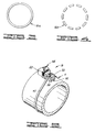
- FIG. 3 is an end view of a continuous form of magnet that can be mounted on the plug.
- FIG. 4 is an end view of a plurality of magnets that can be mounted on the plug at respective radial, circumferentially spaced locations.
- FIG. 5 is a perspective view of a portion of the tubing to which a particular embodiment of a sensor of the present invention is connected.
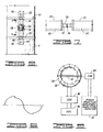
- FIG. 6 is an elevational representation of part of the sensor embodiment shown in FIG. 5.
- FIG. 7 is a view of the FIG. 6 representation as taken along line 7-7 in FIG. 6.
- FIG. 8 is a representation of a toroidal core with an exciter winding and a sensing winding used in the sensor embodiment shown in FIG. 5.
- FIG. 9 is a graphical representation of a signal from a sine wave oscillator connected to the exciter winding of the toroidal core shown in FIG. 8.
- FIG. 10 is a more detailed representation of drive and sensing circuitry of the preferred embodiment.
- FIG. 11 is a representation in partial cutaway, of a more detailed implementation of the embodiment of FIGS. 5-8.
- a plug container 2 is mounted atop a tubing 4 that extends into an oil or gas well into which a cement slurry is to be pumped to secure casing or a liner, for example.
- tubing as used herein and in the claims encompasses any tubular element used in association with an oil or gas well and any string of interconnected such elements.
- the part of the tubing 4 shown in FIGS. 1 and 2 can be an out-of-hole extension of the casing or liner to be cemented into the borehole of the well (i.e., one or more tubular sections connected to and extending above the casing or liner).
- the plug container 2 is a conventional type known in the art.
- the embodiment shown in the FIGS. 1 and 2 has only one plug 6, but additional plugs can be used with other types of containers or by stacking additional sections to the plug container 2 or by removing the upper cap of the plug container 2 and loading additional plugs.
- the plug 6 is conventional, except for an element added to it in accordance with the present invention as subsequently described.
- the plug 6 is used by being released adjacent a fluid to separate the fluid from a leading or trailing different stage or type of fluid. As represented in FIG. 2, the plug 6 separates a cement slurry 8 from a following mud slurry 10 pumped behind the plug 6 to drive the cement slurry down the tubing 4, around the lower end of the tubing 4 and up the annulus between the tubing 4 and the wall of the well borehole or an outer casing so that the cement slurry 8 can bond the requisite portion of the tubing 4 in the well.
- This procedure is done in a manner known in the art (e.g., the slurries are pumped into the tubing through inlet coupling 12 attached to the plug container 2, and the plug 6 is released by retracting plunger 14). Additional plugs 6 are used in the same manner. For example, another plug can be released ahead of the cement slurry 8 to separate it from the fluid (e.g., drilling mud) in the well before the cement slurry 8 is pumped into the well.
- the fluid
- the leading and trailing plugs 6 will be at or below the lower end of the tubing 4 because they drop out or land at this point and are not pumped up into the annulus.
- a drill string (not shown) is typically lowered back into the well to drill the borehole deeper. This necessitates drilling out the plugs 6 that have dropped out in known manner during the fluid placement procedure. If the plugs 6, or elements added thereto, are of too hard material, this further drilling can be impeded because the material dulls or damages the cutting or crushing surfaces of the drill bit.
- the present invention adds a special magnetic member 16 to each such plug 6 and couples a magnetic field responsive sensor device 18 to a predetermined location (i.e., at a selected location where sensing is desired) on the outside of the tubing 4.
- a predetermined location i.e., at a selected location where sensing is desired
- a typical location is between the plug container 2 and the mouth of the well.
- the magnetic member 16, shown connected to the member illustrated in FIGS. 1 and 2 as the cementing plug 6, can take any suitable form so long as it establishes a suitable permanent magnetic field at the cementing plug 6.
- the magnetic member 16 is a single magnet having an annular body.
- a continuous ring magnet 16a is illustrated.
- a magnetic member 16b having a plurality of magnets each to be disposed at a respective radius of the cementing plug 6 so that the magnets are spaced from each other circumferentially around the body of the cementing plug 6.
- magnets can be used to obtain different magnetic field orientations (e.g., parallel or perpendicular to a longitudinal axis of the plug 6), but it is contemplated that any suitable magnetic body form and magnetic field direction can be used in the present invention so long as the magnetic field interacts with the sensor 18.
- each body of which the magnetic member 16 is comprised has a soft body so that it can be drilled out by a conventional (e.g., PDC) drill bit lowered into the well after the cementing plug has passed the predetermined sensing location (more specifically, after the cementing procedure has been completed).
- Soft body as used herein and in the claims is limited to mean a magnet made of metal powder bonded together with a hardened polymer resin compound which has cutting properties similar to chalk or gypsum and a mohs hardness of 6 or less.
- each magnet of the magnetic member 16 includes a bonded rare earth polymer.
- One specific type of magnet includes neodymium, iron and boron and is marketed under the mark Magnequench I by the Magnequench Division of General Motors; this magnet has a normal residual induction of approximately 6 kilogauss.
- the sensor means 18 included in the present invention for the purpose of detecting the magnetic field of the magnetic member 16 as the cementing plug 6 passes is the sensor means 18 connected to the outside of the tubing 4 at the predetermined location.
- any suitable type of magnetic field sensor can be used in the broader aspects of the present invention (e.g., Hall effect, fiber optic, Faraday effect)
- the preferred embodiment sensor means 18 represented in FIGS. 5-8 is a flux gate type.
- the preferred embodiment sensor device 18 includes two elongated ferrous pole piece bars 20, 22 connected to the tubing 4.
- the two pole pieces 20, 22 are connected to the tubing 4 in longitudinally aligned, spaced relation to each other. In this orientation, the two pole pieces 20, 22 have facing end surfaces 24, 26, which surfaces preferably are at least in part curved to receive respective portions of a toroidal core 28.
- Each of the pole pieces 20, 22 of the preferred embodiment has a respective bottom surface in which a respective notch 30 is defined so that the air gaps between the pole pieces 20, 22 and the tubing 4 are reduced and so that the pole pieces are adapted to be mounted on tubing of different diameters.
- the sensor device 18 also includes the toroidal core 28 retained between the two pole pieces 20, 22.
- the core 28 is preferably made of an amorphous material, such as METGLAS 2714A, 2820 MB or 2705M from Allied-Signal (Allied Corporation).
- An amorphous core is preferred because it has a very sharp knee on the B-H curve; thus, the flux gate has a sharper and higher level output as the core is driven in and out of saturation.
- an exciter winding 32 Wrapped radially around the circumference of the toroidal core 28 is an exciter winding 32.
- the winding 32 is preferably made of 200 turns of #30 gauge copper magnet wire.
- a sensing winding 34 Wrapped diametrically about the toroidal core 28 overlaying the exciter winding 32 is a sensing winding 34 preferably made of 1,000 turns of #34 gauge copper magnet wire.
- Kapton tape is wrapped over the windings between two supporting fiberglass boards that are adhered to the core 28 with epoxy applied to the outside surfaces.
- the exciter winding 32 connects to an oscillator 36 of moderate output impedance (e.g., less than 1 ohm) through connectors that provide an intrinsically safe barrier 38 of a type known in the art.
- the flux gate loads the sine wave oscillator 36 as shown in FIG. 9 as the core saturates, and this characteristic can be used to gate the sensing circuitry on the output of the flux gate for noise prevention.
- the sensing winding 34 connects through an intrinsically safe barrier 40 to a phase sensitive amplifier and amplitude detector 42 so that an output signal can be obtained and displayed or otherwise used to indicate passage of the plug 6 carrying the magnet 16.
- the oscillator 36 is a Wien bridge type that provides a sine wave output to an inverting unity gain amplifier 44 and buffer amplifiers 46, 48 to drive the exciter winding 32 through the barrier 38 and interconnecting cable.
- the sensing winding 34 connects to the phase and amplitude detector 42 through a cable and the barrier 40.
- the barriers 38, 40 limit the maximum current, voltage and open circuit voltage to the windings 32, 34.
- the sensor device 18 is connected to the tubing 4 by any suitable means.
- the connection is by two nylon cloth straps 50, 52 passed around the pipe or casing 4 and fastened to the pole piece assembly with fasteners 54, 56, respectively, capable of applying tension to the straps (e.g., ratchet straps).
- the present invention further comprises a biasing magnet 58 movably disposed adjacent the sensor means 18 so that the biasing magnet 58 can be selectably disposed relative to the sensor means 18 and the tubing 4 for canceling a magnetic bias induced in the tubing 4. Flux of naturally occurring magnetism from the earth flowing through the tubing 4 and the sensor 18 can create an offset in the response of the sensor 18.
- the biasing magnet 58 sets up a counter magnetic flux to counteract the offset and, if desired, to produce a selected overriding bias to enhance the indicating ability of the sensor 18. For example, an output pulse is normally obtained on each half of the sine wave drive.
- the biasing magnet 58 can be moved, such as by rotation or sliding (e.g., up/down or in/out relative to the tubing 4), to minimize the output pulse on one half of the drive signal (to minimize the saturation of the core).
- the biasing magnet 58 is an ALNICO magnet providing a residual magnetic flux within the range between about 1000 gauss and 2000 gauss.
- FIG. 11 A more specific implementation of the embodiment of FIGS. 5-8 is shown in FIG. 11. Like elements are indicated by the same reference numerals used in FIGS. 5-8.
- Two side plates 60, 62 are connected by screws to the pole pieces 20, 22. Slots are defined in the side plates 60, 62 to receive edges of cards 64, 66 that support the core 28 and its windings 32, 34.
- a top plate 68 is connected by screws between the side plates 60, 62.
- the top plate 68 has a hole 70 that receives a shaft 72 of a holder member 74 that has the biasing magnet 58 secured to it such as by a set screw.
- the shaft 72 can be rotated to position the biasing magnet 58 at the necessary physical orientation to obtain a desired nulling.
- a bushing 76 can be tightened to hold the shaft 72 and the member 74 fixed.
- the top plate 68 has another hole 78 through which respective cables extend to connect the windings 32, 34 to their respective barriers 38, 40.
- the method of the present invention comprises disposing the bonded rare earth polymer magnet 16, of selected configuration and orientation, on the cementing plug 6.
- a cement slurry is pumped through the tubing 4 into the oil or gas well.
- the cementing plug 6 (or one of them) is released into tubing 4 in series with the cement slurry. Depending on when it is released, the plug 6 moves adjacent either the leading end or the trailing end of the cement slurry 8.
- Sensing the cementing plug 6 includes attaching the magnetic field sensor 18 to the tubing 4 at the predetermined location and performing steps of generating a null signal and of changing the null signal using the magnetic field sensor 18 to provide output electrical signals from the electrically conductive outer winding 34 disposed about a diameter of the metallic toroidal core 28 around which the electrically conductive inner winding 32 is disposed radially and circumferentially.
- attaching the magnetic field sensor 18 to the tubing 4 includes connecting the two elongated pole pieces 20, 22 longitudinally along the tubing 4 so that the two facing end surfaces 24, 26 are spaced from each other, and connecting the metallic toroidal core 28 within the space between the two pole pieces 20, 22.
- a flux is set up in the core 28 by current in the exciter winding 32.
- the aforementioned step of generating a null signal is performed in response to providing a biasing magnetic field in opposition to a magnetic field naturally occurring in the tubing 4 at the predetermined location. This includes connecting and suitably adjusting the position of the biasing magnet 58 adjacent the sensor 18. Nulling involves canceling the effect of the naturally existing fields so that the sensing winding 34 has zero net flux linkages.
- the aforementioned step of changing the null signal to an indicator signal is performed in response to the bonded rare earth polymer magnet 16 moving in the tubing 4 to the predetermined location.
- the net flux linked by the sensing winding 34 is no longer zero, which induces a current in the winding 34 proportional to the difference of the external flux and the core flux.
Landscapes
- Geology (AREA)
- Life Sciences & Earth Sciences (AREA)
- Engineering & Computer Science (AREA)
- Physics & Mathematics (AREA)
- Mining & Mineral Resources (AREA)
- Geophysics (AREA)
- Environmental & Geological Engineering (AREA)
- Fluid Mechanics (AREA)
- General Life Sciences & Earth Sciences (AREA)
- Geochemistry & Mineralogy (AREA)
- Investigating Or Analyzing Materials By The Use Of Magnetic Means (AREA)
- Geophysics And Detection Of Objects (AREA)
- Earth Drilling (AREA)
Applications Claiming Priority (2)
| Application Number | Priority Date | Filing Date | Title |
|---|---|---|---|
| US08/040,708 US5323856A (en) | 1993-03-31 | 1993-03-31 | Detecting system and method for oil or gas well |
| US40708 | 1998-03-18 |
Publications (2)
| Publication Number | Publication Date |
|---|---|
| EP0618347A2 true EP0618347A2 (de) | 1994-10-05 |
| EP0618347A3 EP0618347A3 (de) | 1995-05-31 |
Family
ID=21912484
Family Applications (1)
| Application Number | Title | Priority Date | Filing Date |
|---|---|---|---|
| EP94300854A Withdrawn EP0618347A3 (de) | 1993-03-31 | 1994-02-04 | Einbringen von Zement in ein Bohrloch. |
Country Status (5)
| Country | Link |
|---|---|
| US (1) | US5323856A (de) |
| EP (1) | EP0618347A3 (de) |
| AU (1) | AU5477094A (de) |
| CA (1) | CA2120109A1 (de) |
| NO (1) | NO940629L (de) |
Cited By (4)
| Publication number | Priority date | Publication date | Assignee | Title |
|---|---|---|---|---|
| GB2413814A (en) * | 2002-04-10 | 2005-11-09 | Bj Services Co | System and method of detecting the launch of a device in oilfield applications |
| US7066256B2 (en) | 2002-04-10 | 2006-06-27 | Bj Services Company | Apparatus and method of detecting interfaces between well fluids |
| EP2372080A3 (de) * | 2010-04-02 | 2011-11-02 | Weatherford/Lamb, Inc. | Indexierungshülse für Mehrstufen-Frakturierung in einem Arbeitsgang |
| US8403068B2 (en) | 2010-04-02 | 2013-03-26 | Weatherford/Lamb, Inc. | Indexing sleeve for single-trip, multi-stage fracing |
Families Citing this family (52)
| Publication number | Priority date | Publication date | Assignee | Title |
|---|---|---|---|---|
| GB2306657B (en) * | 1995-10-18 | 1999-10-27 | Tuijl Bert Van | A detector |
| US5967231A (en) * | 1997-10-31 | 1999-10-19 | Halliburton Energy Services, Inc. | Plug release indication method |
| US6563303B1 (en) * | 1998-04-14 | 2003-05-13 | Bechtel Bwxt Idaho, Llc | Methods and computer executable instructions for marking a downhole elongate line and detecting same |
| US6597175B1 (en) | 1999-09-07 | 2003-07-22 | Halliburton Energy Services, Inc. | Electromagnetic detector apparatus and method for oil or gas well, and circuit-bearing displaceable object to be detected therein |
| US6445187B1 (en) | 2000-04-10 | 2002-09-03 | Jerry R. Montgomery | System for the measurement of electrical characteristics of geological formations from within steel cased wells using magnetic circuits |
| DE20008413U1 (de) * | 2000-05-11 | 2001-09-13 | CAMERON GmbH, 29227 Celle | Messvorrichtung |
| AU781387B2 (en) * | 2000-11-03 | 2005-05-19 | Noble Engineering And Development Ltd. | Instrumented cementing plug and system |
| EP1319800B1 (de) * | 2001-12-12 | 2006-02-22 | Cooper Cameron Corporation | System zur Positionsdetektion für eine Einrichtung im Bohrloch |
| US20040211443A1 (en) * | 2002-03-19 | 2004-10-28 | Frank's Casing Crew And Rental Tools, Inc. | Magnetic plug detector |
| US6720764B2 (en) | 2002-04-16 | 2004-04-13 | Thomas Energy Services Inc. | Magnetic sensor system useful for detecting tool joints in a downhold tubing string |
| US7219730B2 (en) * | 2002-09-27 | 2007-05-22 | Weatherford/Lamb, Inc. | Smart cementing systems |
| GB0403238D0 (en) * | 2004-02-13 | 2004-03-17 | Zenith Oilfield Technology Ltd | Apparatus and method |
| GB0404458D0 (en) * | 2004-03-01 | 2004-03-31 | Zenith Oilfield Technology Ltd | Apparatus & method |
| EP1669769A1 (de) * | 2004-12-13 | 2006-06-14 | Services Pétroliers Schlumberger | Magneto-optischer Sensor |
| US20060182152A1 (en) * | 2005-02-16 | 2006-08-17 | Qi Bi | Combining multiple physical traffic channels in a wireless communication system |
| US20070234789A1 (en) * | 2006-04-05 | 2007-10-11 | Gerard Glasbergen | Fluid distribution determination and optimization with real time temperature measurement |
| US7703548B2 (en) * | 2006-08-16 | 2010-04-27 | Schlumberger Technology Corporation | Magnetic ranging while drilling parallel wells |
| US8462012B2 (en) * | 2007-07-20 | 2013-06-11 | Schlumberger Technology Corporation | Anti-collision method for drilling wells |
| US8307915B2 (en) * | 2008-04-10 | 2012-11-13 | Schlumberger Technology Corporation | System and method for drilling multilateral wells using magnetic ranging while drilling |
| US8827005B2 (en) * | 2008-04-17 | 2014-09-09 | Schlumberger Technology Corporation | Method for drilling wells in close relationship using magnetic ranging while drilling |
| US8596382B2 (en) * | 2008-04-18 | 2013-12-03 | Schlumbeger Technology Corporation | Magnetic ranging while drilling using an electric dipole source and a magnetic field sensor |
| US8439109B2 (en) * | 2008-05-23 | 2013-05-14 | Schlumberger Technology Corporation | System and method for depth measurement and correction during subsea intervention operations |
| US20090308588A1 (en) * | 2008-06-16 | 2009-12-17 | Halliburton Energy Services, Inc. | Method and Apparatus for Exposing a Servicing Apparatus to Multiple Formation Zones |
| US20100044027A1 (en) | 2008-08-20 | 2010-02-25 | Baker Hughes Incorporated | Arrangement and method for sending and/or sealing cement at a liner hanger |
| US20100051264A1 (en) * | 2008-08-29 | 2010-03-04 | Baker Hughes Incorporated | Method and system for monitoring downhole completion operations |
| US8668012B2 (en) | 2011-02-10 | 2014-03-11 | Halliburton Energy Services, Inc. | System and method for servicing a wellbore |
| US8276675B2 (en) * | 2009-08-11 | 2012-10-02 | Halliburton Energy Services Inc. | System and method for servicing a wellbore |
| US8695710B2 (en) | 2011-02-10 | 2014-04-15 | Halliburton Energy Services, Inc. | Method for individually servicing a plurality of zones of a subterranean formation |
| US8668016B2 (en) | 2009-08-11 | 2014-03-11 | Halliburton Energy Services, Inc. | System and method for servicing a wellbore |
| US8272443B2 (en) * | 2009-11-12 | 2012-09-25 | Halliburton Energy Services Inc. | Downhole progressive pressurization actuated tool and method of using the same |
| US8930143B2 (en) | 2010-07-14 | 2015-01-06 | Halliburton Energy Services, Inc. | Resolution enhancement for subterranean well distributed optical measurements |
| US8584519B2 (en) | 2010-07-19 | 2013-11-19 | Halliburton Energy Services, Inc. | Communication through an enclosure of a line |
| US20120014211A1 (en) * | 2010-07-19 | 2012-01-19 | Halliburton Energy Services, Inc. | Monitoring of objects in conjunction with a subterranean well |
| US8893811B2 (en) | 2011-06-08 | 2014-11-25 | Halliburton Energy Services, Inc. | Responsively activated wellbore stimulation assemblies and methods of using the same |
| US8899334B2 (en) | 2011-08-23 | 2014-12-02 | Halliburton Energy Services, Inc. | System and method for servicing a wellbore |
| US8662178B2 (en) | 2011-09-29 | 2014-03-04 | Halliburton Energy Services, Inc. | Responsively activated wellbore stimulation assemblies and methods of using the same |
| US8991509B2 (en) | 2012-04-30 | 2015-03-31 | Halliburton Energy Services, Inc. | Delayed activation activatable stimulation assembly |
| US9784070B2 (en) | 2012-06-29 | 2017-10-10 | Halliburton Energy Services, Inc. | System and method for servicing a wellbore |
| WO2014018844A1 (en) * | 2012-07-27 | 2014-01-30 | Schlumberger Canada Limited | Object detection system and methodology |
| WO2015051225A1 (en) | 2013-10-03 | 2015-04-09 | Schlumberger Canada Limited | Pipe damage assessment system and method |
| MX381395B (es) * | 2013-11-11 | 2025-03-12 | Halliburton Energy Services Inc | Sistemas y métodos para rastrar la posición de un proyectil en el fondo del pozo. |
| US9797218B2 (en) * | 2014-05-15 | 2017-10-24 | Baker Hughes Incorporated | Wellbore systems with hydrocarbon leak detection apparatus and methods |
| WO2015187923A1 (en) | 2014-06-04 | 2015-12-10 | Schlumberger Canada Limited | Pipe defect assessment system and method |
| AU2014405923B2 (en) * | 2014-09-11 | 2017-11-23 | Halliburton Energy Services, Inc. | Rare earth alloys as borehole markers |
| US20170122096A1 (en) * | 2015-11-04 | 2017-05-04 | Tesco Corporation | Cement plug detection system and method |
| US10877000B2 (en) | 2015-12-09 | 2020-12-29 | Schlumberger Technology Corporation | Fatigue life assessment |
| US11237132B2 (en) | 2016-03-18 | 2022-02-01 | Schlumberger Technology Corporation | Tracking and estimating tubing fatigue in cycles to failure considering non-destructive evaluation of tubing defects |
| CN109083631B (zh) * | 2018-09-14 | 2019-07-19 | 东北石油大学 | 利用连续油管修补固井水泥裂隙的装置及修补方法 |
| US12342989B2 (en) * | 2019-05-31 | 2025-07-01 | The Boeing Company | Optical fiber sensor system |
| WO2022216286A1 (en) * | 2021-04-07 | 2022-10-13 | Halliburton Energy Services, Inc. | Induction loop cementing progress detection |
| US11761299B2 (en) * | 2021-05-19 | 2023-09-19 | Innovex Downhole Solutions, Inc. | Cement plug and bridge plug assembly and method |
| US12210131B2 (en) * | 2023-05-19 | 2025-01-28 | Fmc Technologies, Inc. | Seal pocket detection assembly |
Family Cites Families (27)
| Publication number | Priority date | Publication date | Assignee | Title |
|---|---|---|---|---|
| US2201311A (en) * | 1936-12-24 | 1940-05-21 | Halliburton Oil Well Cementing | Apparatus for indicating the position of devices in pipes |
| US3116452A (en) * | 1960-06-06 | 1963-12-31 | Shell Oil Co | Eddy current type pipeline flaw testing and flaw location marking device |
| US3562636A (en) * | 1969-05-20 | 1971-02-09 | Minnesota Mining & Mfg | Bridge circuit having plural compensating arms |
| GB1319586A (en) * | 1969-10-06 | 1973-06-06 | Findlay Irvine Ltd | Displacement transducers |
| SE347356B (de) * | 1970-03-20 | 1972-07-31 | Essem Metotest Ab | |
| US3843923A (en) * | 1973-07-05 | 1974-10-22 | Stewart & Stevenson Inc Jim | Well pipe joint locator using a ring magnet and two sets of hall detectors surrounding the pipe |
| US3878453A (en) * | 1973-09-21 | 1975-04-15 | Trans Canada Pipelines Ltd | Pipeline signalling systems and techniques |
| US4023092A (en) * | 1974-04-29 | 1977-05-10 | W. R. Grace & Co. | Apparatus for sensing metal in wells |
| US3883797A (en) * | 1974-06-20 | 1975-05-13 | Abram Lvovich Abrukin | Apparatus for checking the continuity of metallic pipes using an oscillator whose frequency changes at discontinuities |
| US4038609A (en) * | 1976-07-19 | 1977-07-26 | Edwin Langberg | Replica bridge sensing circuit |
| US4121657A (en) * | 1977-05-16 | 1978-10-24 | Eastman Whipstock, Inc. | Position indicator for downhole tool |
| US4206810A (en) * | 1978-06-20 | 1980-06-10 | Halliburton Company | Method and apparatus for indicating the downhole arrival of a well tool |
| JPS5843502A (ja) * | 1981-09-09 | 1983-03-14 | Aisin Seiki Co Ltd | ウイ−ガンド効果素子 |
| GB2107063B (en) * | 1981-09-23 | 1985-09-11 | British Gas Corp | Fixing geographical reference of pipeline pigs in pipelines |
| DE3143208C2 (de) * | 1981-10-30 | 1984-07-05 | Max-E. Dipl.-Ing. 7320 Göppingen Reeb | Identifizierungsanordnung in Form eines an einem Gegenstand anbringbaren etikettartigen Streifens und Verfahren zu deren Herstellung |
| DE3221500A1 (de) * | 1982-06-07 | 1983-12-08 | Max-E. Dipl.-Ing. 7320 Göppingen Reeb | Identifizierungsanordnung in form eines an einem gegenstand anbringbaren gebildes und verfahren zur herstellung |
| US4468967A (en) * | 1982-11-03 | 1984-09-04 | Halliburton Company | Acoustic plug release indicator |
| US4572293A (en) * | 1984-08-31 | 1986-02-25 | Standard Oil Company (Now Amoco Corporation) | Method of placing magnetic markers on collarless cased wellbores |
| US4638278A (en) * | 1986-01-14 | 1987-01-20 | Halliburton Company | Magnetic detector apparatus |
| US4847552A (en) * | 1987-07-07 | 1989-07-11 | The Boeing Company | Detection of electrically conductive materials beneath surface coatings employing eddy currents |
| US4972198A (en) * | 1987-08-31 | 1990-11-20 | Monarch Marking Systems, Inc. | Multiple loop antenna |
| DE3733808A1 (de) * | 1987-10-07 | 1989-05-11 | T E C Computer Gmbh | Vorrichtung zur ueberwachung von sachen und/oder personen |
| JPH0652258B2 (ja) * | 1987-11-09 | 1994-07-06 | 日本核燃料開発株式会社 | 過電流欠陥探傷方法及びその装置 |
| US4835524A (en) * | 1987-12-17 | 1989-05-30 | Checkpoint System, Inc. | Deactivatable security tag |
| US4933640A (en) * | 1988-12-30 | 1990-06-12 | Vector Magnetics | Apparatus for locating an elongated conductive body by electromagnetic measurement while drilling |
| US4928520A (en) * | 1989-03-02 | 1990-05-29 | Halliburton Company | Plug release indicator |
| US5006800A (en) * | 1989-11-06 | 1991-04-09 | General Electric Company | Eddy current imaging apparatus and method using phase difference detection |
-
1993
- 1993-03-31 US US08/040,708 patent/US5323856A/en not_active Expired - Lifetime
-
1994
- 1994-01-28 AU AU54770/94A patent/AU5477094A/en not_active Abandoned
- 1994-02-04 EP EP94300854A patent/EP0618347A3/de not_active Withdrawn
- 1994-02-24 NO NO940629A patent/NO940629L/no unknown
- 1994-03-28 CA CA002120109A patent/CA2120109A1/en not_active Abandoned
Cited By (8)
| Publication number | Priority date | Publication date | Assignee | Title |
|---|---|---|---|---|
| GB2413814A (en) * | 2002-04-10 | 2005-11-09 | Bj Services Co | System and method of detecting the launch of a device in oilfield applications |
| US7066256B2 (en) | 2002-04-10 | 2006-06-27 | Bj Services Company | Apparatus and method of detecting interfaces between well fluids |
| GB2413814B (en) * | 2002-04-10 | 2006-06-28 | Bj Services Co | System and method for detecting the launch of a device in oilfield applications |
| EP2372080A3 (de) * | 2010-04-02 | 2011-11-02 | Weatherford/Lamb, Inc. | Indexierungshülse für Mehrstufen-Frakturierung in einem Arbeitsgang |
| AU2011201418B2 (en) * | 2010-04-02 | 2013-02-07 | Weatherford Technology Holdings, Llc | Indexing sleeve for single-trip, multi-stage fracing |
| US8403068B2 (en) | 2010-04-02 | 2013-03-26 | Weatherford/Lamb, Inc. | Indexing sleeve for single-trip, multi-stage fracing |
| US8505639B2 (en) | 2010-04-02 | 2013-08-13 | Weatherford/Lamb, Inc. | Indexing sleeve for single-trip, multi-stage fracing |
| US9441457B2 (en) | 2010-04-02 | 2016-09-13 | Weatherford Technology Holdings, Llc | Indexing sleeve for single-trip, multi-stage fracing |
Also Published As
| Publication number | Publication date |
|---|---|
| EP0618347A3 (de) | 1995-05-31 |
| AU5477094A (en) | 1994-10-06 |
| NO940629D0 (no) | 1994-02-24 |
| NO940629L (no) | 1994-10-03 |
| US5323856A (en) | 1994-06-28 |
| CA2120109A1 (en) | 1994-10-01 |
Similar Documents
| Publication | Publication Date | Title |
|---|---|---|
| US5323856A (en) | Detecting system and method for oil or gas well | |
| US6843318B2 (en) | Method and system for determining the position and orientation of a device in a well casing | |
| US6411084B1 (en) | Magnetically activated well tool | |
| US4443762A (en) | Method and apparatus for detecting the direction and distance to a target well casing | |
| CA2482096C (en) | Magnetically activated well tool | |
| CA2412273C (en) | Downhole magnetic-field based feature detector | |
| US6429653B1 (en) | Method and apparatus for protecting a sensor in a drill collar | |
| US4647853A (en) | Mud turbine tachometer | |
| US20110227564A1 (en) | Probe for analysis of a string of rods or tubes in a well | |
| GB2388432A (en) | Subsurface monitoring and borehole placement | |
| US9217320B2 (en) | Magnetically clamping a downhole component to a direction of a borehole casing | |
| CN103299215A (zh) | 具有外部磁体的核磁共振工具 | |
| GB2380799A (en) | Non-invasive detectors for wells | |
| US2967994A (en) | Casing joint locator | |
| EP0301671B1 (de) | Verfahren zur Magnetisierung von Bohrlochrohren | |
| US5252918A (en) | Apparatus and method for electromagnetically detecting the passing of a plug released into a well by a bridge circuit | |
| US3233170A (en) | Magnetic stuck pipe locator and detonator using a single line to transmit signals | |
| US4289024A (en) | Well casing free-point indicator | |
| GB2299915A (en) | Communication along a drill string | |
| GB2405212A (en) | Downhole magnetic field based feature detector | |
| US20040154833A1 (en) | Long range data transmitter for horizontal directional drilling | |
| US3267365A (en) | Apparatus for detecting magnetic anomalies | |
| EP0196829A2 (de) | Bohrlochwerkzeug | |
| SA113340950B1 (ar) | طريقة وجهاز لقياس قرب حفرة بئر أثناء الحفر | |
| US12516601B1 (en) | Casing collar locator |
Legal Events
| Date | Code | Title | Description |
|---|---|---|---|
| PUAI | Public reference made under article 153(3) epc to a published international application that has entered the european phase |
Free format text: ORIGINAL CODE: 0009012 |
|
| AK | Designated contracting states |
Kind code of ref document: A2 Designated state(s): DE DK ES FR GB IT NL |
|
| PUAL | Search report despatched |
Free format text: ORIGINAL CODE: 0009013 |
|
| AK | Designated contracting states |
Kind code of ref document: A3 Designated state(s): DE DK ES FR GB IT NL |
|
| STAA | Information on the status of an ep patent application or granted ep patent |
Free format text: STATUS: THE APPLICATION IS DEEMED TO BE WITHDRAWN |
|
| 18D | Application deemed to be withdrawn |
Effective date: 19951201 |