EP0618391A2 - Fluidleitung aus Kunststoff - Google Patents
Fluidleitung aus Kunststoff Download PDFInfo
- Publication number
- EP0618391A2 EP0618391A2 EP94400604A EP94400604A EP0618391A2 EP 0618391 A2 EP0618391 A2 EP 0618391A2 EP 94400604 A EP94400604 A EP 94400604A EP 94400604 A EP94400604 A EP 94400604A EP 0618391 A2 EP0618391 A2 EP 0618391A2
- Authority
- EP
- European Patent Office
- Prior art keywords
- fluid
- materials
- pipe according
- fluid pipe
- layer
- Prior art date
- Legal status (The legal status is an assumption and is not a legal conclusion. Google has not performed a legal analysis and makes no representation as to the accuracy of the status listed.)
- Withdrawn
Links
Images

Classifications
-
- F—MECHANICAL ENGINEERING; LIGHTING; HEATING; WEAPONS; BLASTING
- F16—ENGINEERING ELEMENTS AND UNITS; GENERAL MEASURES FOR PRODUCING AND MAINTAINING EFFECTIVE FUNCTIONING OF MACHINES OR INSTALLATIONS; THERMAL INSULATION IN GENERAL
- F16L—PIPES; JOINTS OR FITTINGS FOR PIPES; SUPPORTS FOR PIPES, CABLES OR PROTECTIVE TUBING; MEANS FOR THERMAL INSULATION IN GENERAL
- F16L11/00—Hoses, i.e. flexible pipes
- F16L11/14—Hoses, i.e. flexible pipes made of rigid material, e.g. metal or hard plastics
- F16L11/15—Hoses, i.e. flexible pipes made of rigid material, e.g. metal or hard plastics corrugated
-
- F—MECHANICAL ENGINEERING; LIGHTING; HEATING; WEAPONS; BLASTING
- F16—ENGINEERING ELEMENTS AND UNITS; GENERAL MEASURES FOR PRODUCING AND MAINTAINING EFFECTIVE FUNCTIONING OF MACHINES OR INSTALLATIONS; THERMAL INSULATION IN GENERAL
- F16L—PIPES; JOINTS OR FITTINGS FOR PIPES; SUPPORTS FOR PIPES, CABLES OR PROTECTIVE TUBING; MEANS FOR THERMAL INSULATION IN GENERAL
- F16L9/00—Rigid pipes
- F16L9/12—Rigid pipes of plastics with or without reinforcement
-
- F—MECHANICAL ENGINEERING; LIGHTING; HEATING; WEAPONS; BLASTING
- F16—ENGINEERING ELEMENTS AND UNITS; GENERAL MEASURES FOR PRODUCING AND MAINTAINING EFFECTIVE FUNCTIONING OF MACHINES OR INSTALLATIONS; THERMAL INSULATION IN GENERAL
- F16L—PIPES; JOINTS OR FITTINGS FOR PIPES; SUPPORTS FOR PIPES, CABLES OR PROTECTIVE TUBING; MEANS FOR THERMAL INSULATION IN GENERAL
- F16L11/00—Hoses, i.e. flexible pipes
- F16L11/04—Hoses, i.e. flexible pipes made of rubber or flexible plastics
- F16L2011/047—Hoses, i.e. flexible pipes made of rubber or flexible plastics with a diffusion barrier layer
Definitions
- the invention relates to a fluid line based on plastic material (s).
- It relates in particular, but is not limited thereto, to pipes, fittings, tubes, pipes, tubing and conduits based on plastic material (s) suitable for use in the locomotion engine industry and, in particular, the automotive industry, for example in the engine compartment of vehicles with thermal engines but also as vent pipes for fuel tanks or also as parts of engine cooling circuits or air conditioning circuits for passenger compartments automobile or locomotion equipment other than automobiles.
- plastic material suitable for use in the locomotion engine industry and, in particular, the automotive industry, for example in the engine compartment of vehicles with thermal engines but also as vent pipes for fuel tanks or also as parts of engine cooling circuits or air conditioning circuits for passenger compartments automobile or locomotion equipment other than automobiles.
- Fluid lines in particular those associated with automobile heat engines, for example for the conveyance of air between the air intake and the air filter, then between the latter and the engine or for routing of a coolant liquid for cooling the engine, such as a usual water / ethylene-glycol mixture or a more specific two-phase mixture, of the type used in two-phase cooling systems, have been carried out for many years in elastomeric materials (EPDM, NBR, epichlorohydrin rubber or silicone rubber for applications in high temperature areas of the engine compartment).
- a coolant liquid for cooling the engine such as a usual water / ethylene-glycol mixture or a more specific two-phase mixture, of the type used in two-phase cooling systems
- elastomeric materials are also used for the manufacture of pipes, tubes, hoses, fittings, pipes or tubes intended for the conveyance of other fluids, for example the fuel of heat engines or mixtures of air and vapor of fuel, as in the vent tubes of automobile tanks, or lubricants, transmission fluids and the like. If the known devices made from these materials are satisfactory, they can however be difficult to manufacture, in particular when their geometric shape is complex, on the one hand and are, on the other hand, generally of a relatively high weight.
- thermoplastic material s
- simple (s) or complex (s) materials
- thermoplastic elastomers TPE
- TPE thermoplastic elastomers
- These mono- or polyphase materials have thus been proposed for the manufacture of clean air ducts for automobile engines, either in the form of tubes made of a single material and with rigid part (s). ) associated with deformable parts, such as bellows, either in the form of multilayer tubes, completely rigid or with deformable parts, as described, for example, in EP-A1-0 492 129.
- the devices described in this document and the central axis of which can be curved in two or three dimensions of space they are then designated under the names of "2D” or "3D” devices -, are constituted by a hollow body made of a first plastic material, preferably made by extrusion blow molding, spacers at the periphery of the hollow body made of a second plastic material and an outer layer over the entire hollow body, with the exception of the areas where the spacers prevail.
- an object of the invention to provide such a pipe of complex shape, capable of having various mechanical characteristics at different points along its length with, where appropriate, rigid parts and flexible parts, such as bellows or, along the same pipe and arranged sequentially next to each other, rigid parts and deformable parts which are not bellows, said parts forming a single piece without solution of continuity between them.
- an object of the invention to provide such a pipe which can be manufactured by techniques of the type of those mentioned above of extrusion blow-molding or extrusion-suction, in complex spatial forms and at an economically attractive operating cost.
- a pipe based on simple or complex thermoplastic material (s), in particular elastomeric thermoplastic materials (TPE) comprising, where appropriate, parts of different shapes, stiffnesses and mechanical characteristics between its ends is characterized, according to the invention, in that it is constituted over practically its entire length in at least two layers of materials with different properties and one of which is chosen according to its characteristics of resistance to aggression of the transported fluid, on the one hand, and for its impermeability to said fluid, on the other hand.
- TPE elastomeric thermoplastic materials
- thermoplastic elastomeric materials that the invention envisages using for the production of the improved fluid lines that it offers are advantageously chosen from polyamides 6, polyamides 6.6, polyamides 11 or 12, polyamides 4.6 or 6.10 or 6.12, elastomeric polyamide alloys, polypropylene, polyethylene, polyphenylene sulfides (PPS), polybutylene terephthalates (PBT), polyethylene terephthalates (PET), polyethersulfones (PES), polyetheretherketones (PE) ), polyimides, polyamideimides, polyether block amides (PEBA), polyetheresters (TEEE), etc., these materials being, where appropriate, loaded, for example using glass fibers.
- polyamides 6, polyamides 6.6, polyamides 11 or 12, polyamides 4.6 or 6.10 or 6.12 elastomeric polyamide alloys
- polypropylene polyethylene
- PPS polyphenylene sulfides
- PBT polybutylene terephthalates
- the layer chosen for its characteristics of resistance to attack by the transported fluid and for its impermeability to said fluid is an internal layer of the pipe chosen from olefin polymers, polyethylenes or polypropylenes.
- the layer with good characteristics of resistance to aggression and with good characteristics of impermeability to the transported fluid is made of fluoropolymer.
- said fluoropolymer is polyvinylidene fluoride.
- the fluoropolymer advantageously polyvinylidene fluoride, preferably forms the layer the innermost of the pipe.
- Polyvinylidene fluoride the melting point of which is around 170-175 ° C, can be easily used by extrusion blow-molding or extrusion-suction techniques. Its water impermeability characteristics, on the one hand and, on the other hand, good temperature resistance in a range between -45 ° and 150 ° C make it a particularly suitable material for resisting liquids aggressive, such as those in the usual water / ethylene glycol mixture cooling circuits or those used in two-phase cooling systems.
- the invention provides that the materials constituting the layers of the fluid line are joined together without an intermediate bonding layer, when they are physically and chemically compatible.
- one or more intermediate layer ensures (s) the connection of the internal, external and, if appropriate, other layers of the pipe.
- the invention proposes to produce the pipes as defined above by the extrusion-blowing or extrusion-suction techniques.
- the fluid pipes according to the invention advantageously have a diameter between 10 and 80 mm, a thickness between 0.5 and 5 mm and can reach a developed length under pressure of the order of about 2 m, including when their medium axis is curved in two (2D) or three dimensions of space (3D) with a number of elbows which can be of the order of six.
- the invention also relates to the use of a fluid pipe as defined above as a pipe, tube, pipe, fitting or tubing for conveying aggressive fluid, such as the coolant for cooling a heat engine. , the fuel of such an engine, air / fuel vapor mixtures, etc.
- a fluid line according to the invention, 10 is shown diagrammatically in FIGS. 1 and 2 as a pipeline for transporting liquid or gaseous fluid, such as a heat engine coolant or a mixture of air and vapor of fuel from such an engine. It comprises, between two end caps 11 and 12, sections or rectilinear flexible or rigid parts, 13 and 14 adjacent to the end caps and curved parts 15 and 16 (also flexible or rigid) interposed between the parts 13 and 14 and a bellows. 20 which gives the pipe a relatively large deformation possibility.
- the mean axis of the pipe 10 is curved in the three dimensions of the space (3D) and is made from plastic material (s) in particular from simple thermoplastic elastomers (TPE) or in the form of alloys elastomeric.
- the preferred materials for its production are advantageously chosen from polyamides 6, polyamides 6.6, polyamides 11 or 12, polyamides 4.6 or 6.10 or 6.12, elastomeric alloys of polyamides, polypropylene, polyethylene, polyphenylenesulfides (PPS), polybutyleneterephthalates (PBT), polyethylene terephthalates (PET), polyethersulfones (PES), polyetheretherketone (PEEK), polyimides, polyamideimides, polyether block amides (PEBA), polyetheresters (TEEE), etc. materials being, where appropriate, loaded, for example using glass fibers.
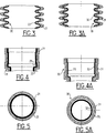
- the pipe 10 is formed over practically its entire length, and in particular at the level of the bellows 20, FIG. 3, in at least two layers of materials with different properties, namely an outer layer 21 and an inner layer 22, the latter being chosen as a function of its characteristics of resistance to attack by the transported fluid, on the one hand and for its impermeability to said fluid, on the other hand.
- the outer layer 21 is made of an elastomeric thermoplastic material, for example an elastomeric EPDM / polypropylene alloy, of the type of those sold under the name "Santoprene” (a registered trademark of the company MONSANTO) and the inner layer 22 is, in general, made of an olefinic polymer, polyethylene or polypropylene, the two layers being joined together without an intermediate bonding layer.
- an elastomeric thermoplastic material for example an elastomeric EPDM / polypropylene alloy, of the type of those sold under the name "Santoprene” (a registered trademark of the company MONSANTO)
- the inner layer 22 is, in general, made of an olefinic polymer, polyethylene or polypropylene, the two layers being joined together without an intermediate bonding layer.
- the invention also envisages constituting the external layer 21 of a given pipe in materials which are totally different in their chemical nature or, as a variant, of the same family but which differ from one another as regards their characteristics. mechanical, in particular of hardness, for example due to the addition of loads so that said pipe has between its two ends and sequentially adjacent to each other parts of different stiffness and / or flexibility, including in the absence of bellows.
- the pipe can be provided, if necessary, with external projecting parts, with or without insert, and the end pieces can have the same cross section, for example circular or, as a variant, have different contours, for example one be circular and the other rectangular.
- the end pieces 11 and 12 can be shaped to provide a groove 23 for housing a seal, for example an O-ring seal.
- the pipe 30 has the same configuration as that shown in FIGS. 1 and 2, that is to say provided at its ends with end pieces like 11 and 12 (FIG. 4A ), a bellows similar to the bellows 20 (FIG. 3A) and rectilinear or curved parts, the mean axis of the pipe 30 being bent in the three directions of space (3D).
- the pipe also comprises an external layer 31 and an internal layer 32, extending over all or substantially the entire length of the pipe, including in line with the bellows, the layers 31 and 32 being, however, in this embodiment joined together by a bonding layer 35.
- the outer layer 31 can be based on polyamide and the inner layer 32 based on polyethylene.
- the outer layer 31 is based on polyamide and the inner layer 32 based on polypropylene.
- the outer layer 31 of a given pipe can be made of completely different materials or of materials of the same family but with different mechanical characteristics, for example rigid polyamide and flexible polyamide , so that said pipe can consist of a sequence of deformable and / or non-deformable parts.
- the internal layer 32 is made of fluoropolymer and, in a particularly advantageous embodiment, of polyvinylidene fluoride while the outer layer 31 is made of an elastomeric thermoplastic material (polypropylene / EPDM), for example of a material of the type sold under the name "Santoprene” (a registered trademark of the company MONSANTO).
- polypropylene / EPDM elastomeric thermoplastic material
- the layer 32 which is that having good characteristics of resistance to aggression of the transported fluid and impermeability to said fluid does not form the innermost layer of the pipe but is lined, on its face internal layer closest to axis A, an additional or auxiliary layer.
- the invention provides for making it by extrusion-blowing or extrusion-suction techniques , which make it possible to obtain complex shapes, in the three dimensions of space, on the one hand and, on the other hand, a one-piece pipe, with no solution of continuity between its various constituent parts, rigid or flexible, -as the bellows 20, 30, - or parts which is not in the form of a bellows but which is however deformable.
Landscapes
- Engineering & Computer Science (AREA)
- General Engineering & Computer Science (AREA)
- Mechanical Engineering (AREA)
- Rigid Pipes And Flexible Pipes (AREA)
- Laminated Bodies (AREA)
- Joints Allowing Movement (AREA)
Applications Claiming Priority (2)
| Application Number | Priority Date | Filing Date | Title |
|---|---|---|---|
| FR9303577A FR2703428B1 (fr) | 1993-03-29 | 1993-03-29 | Conduite de fluide à base de matière(s) plastique(s). |
| FR9303577 | 1993-03-29 |
Publications (2)
| Publication Number | Publication Date |
|---|---|
| EP0618391A2 true EP0618391A2 (de) | 1994-10-05 |
| EP0618391A3 EP0618391A3 (de) | 1994-11-17 |
Family
ID=9445444
Family Applications (1)
| Application Number | Title | Priority Date | Filing Date |
|---|---|---|---|
| EP19940400604 Withdrawn EP0618391A3 (de) | 1993-03-29 | 1994-03-21 | Fluidleitung aus Kunststoff. |
Country Status (3)
| Country | Link |
|---|---|
| EP (1) | EP0618391A3 (de) |
| JP (1) | JPH06316008A (de) |
| FR (1) | FR2703428B1 (de) |
Cited By (9)
| Publication number | Priority date | Publication date | Assignee | Title |
|---|---|---|---|---|
| EP0791775A1 (de) * | 1996-02-22 | 1997-08-27 | Hutchinson | Transportleitung für eine unter erhöhtem Druck und erhöhter Temperatur stehende Flüssigkeit |
| EP0791153B1 (de) * | 1994-11-02 | 2002-03-20 | Atofina | Rohrleitungen aus polyamid und polyolefin zum gastransport |
| EP1533554A1 (de) * | 2003-11-20 | 2005-05-25 | Veritas Ag | Schlauch mit Rippen aufweisender Innenschicht |
| DE102005051189B3 (de) * | 2005-10-26 | 2007-03-01 | Dirk Bodeutsch | Medienführendes Verbindungselement und ein Verfahren zu seiner Herstellung |
| EP2677220A1 (de) * | 2012-06-20 | 2013-12-25 | TI Automotive Engineering Centre (Heidelberg) GmbH | Rohr für den Transport eines Kühlmittels einer Klimaanlage und Rohranordnung |
| EP2816272B1 (de) | 2010-12-08 | 2017-04-19 | Voss Automotive GmbH | Beheizbare Fluidleitung, deren Verwendung sowie Verfahren zu ihrer Herstellung |
| CN112393030A (zh) * | 2019-08-15 | 2021-02-23 | 上海亚大汽车塑料制品有限公司 | 阻燃冷却管总成 |
| EP3741796A4 (de) * | 2018-01-15 | 2021-09-29 | Toray Industries, Inc. | Rohrförmiger einstückig geformter artikel und herstellungsverfahren für rohrförmigen einstückig geformten artikel |
| CN114533208A (zh) * | 2020-11-24 | 2022-05-27 | 先健科技(深圳)有限公司 | 穿刺鞘及可调弯系统 |
Families Citing this family (7)
| Publication number | Priority date | Publication date | Assignee | Title |
|---|---|---|---|---|
| JP3318916B2 (ja) * | 1994-04-27 | 2002-08-26 | 株式会社明治ゴム化成 | ウォータージェット用超高圧ホース |
| JPH10246383A (ja) * | 1997-03-04 | 1998-09-14 | Hayakawa Rubber Co Ltd | 配管構造及びその製造方法 |
| FR2797673B1 (fr) | 1999-08-19 | 2001-11-09 | Coutier Moulage Gen Ind | Canalisation pour circuit de refroidissement |
| JP4235021B2 (ja) * | 2002-04-18 | 2009-03-04 | サンデン商事株式会社 | 自在管継手 |
| EP3482987B1 (de) * | 2018-03-13 | 2020-05-13 | TI Automotive (Fuldabrück) GmbH | Verwendung einer rohrleitung als temperier-rohrleitung |
| KR102106201B1 (ko) * | 2018-04-17 | 2020-05-06 | 동의대학교 산학협력단 | 잠수함 배기가스의 수면 배출온도를 계측하기 위한 축소모형시험장치 |
| FR3119433B1 (fr) * | 2021-02-04 | 2023-10-20 | Akwel | Composant de transfert de fluide avec région flexible formant soufflet. |
Family Cites Families (3)
| Publication number | Priority date | Publication date | Assignee | Title |
|---|---|---|---|---|
| DE7429479U (de) * | 1974-12-05 | Vorneweg W Kg | Kunststoffschlauch für Kraftstoffleitungen | |
| JPS5940109B2 (ja) * | 1978-10-06 | 1984-09-28 | ダイキン工業株式会社 | 積層体および積層体形成方法 |
| FR2650777B1 (fr) * | 1989-08-09 | 1991-11-29 | Hutchinson Sa | Tuyau souple a bonnes caracteristiques de resistance aux agressions externes et son procede de fabrication |
-
1993
- 1993-03-29 FR FR9303577A patent/FR2703428B1/fr not_active Expired - Fee Related
-
1994
- 1994-03-21 EP EP19940400604 patent/EP0618391A3/de not_active Withdrawn
- 1994-03-29 JP JP6082476A patent/JPH06316008A/ja active Pending
Cited By (10)
| Publication number | Priority date | Publication date | Assignee | Title |
|---|---|---|---|---|
| EP0791153B1 (de) * | 1994-11-02 | 2002-03-20 | Atofina | Rohrleitungen aus polyamid und polyolefin zum gastransport |
| EP0791775A1 (de) * | 1996-02-22 | 1997-08-27 | Hutchinson | Transportleitung für eine unter erhöhtem Druck und erhöhter Temperatur stehende Flüssigkeit |
| FR2745354A1 (fr) * | 1996-02-22 | 1997-08-29 | Hutchinson | Conduit de transport de fluide a pression et temperature elevees |
| EP1533554A1 (de) * | 2003-11-20 | 2005-05-25 | Veritas Ag | Schlauch mit Rippen aufweisender Innenschicht |
| DE102005051189B3 (de) * | 2005-10-26 | 2007-03-01 | Dirk Bodeutsch | Medienführendes Verbindungselement und ein Verfahren zu seiner Herstellung |
| EP2816272B1 (de) | 2010-12-08 | 2017-04-19 | Voss Automotive GmbH | Beheizbare Fluidleitung, deren Verwendung sowie Verfahren zu ihrer Herstellung |
| EP2677220A1 (de) * | 2012-06-20 | 2013-12-25 | TI Automotive Engineering Centre (Heidelberg) GmbH | Rohr für den Transport eines Kühlmittels einer Klimaanlage und Rohranordnung |
| EP3741796A4 (de) * | 2018-01-15 | 2021-09-29 | Toray Industries, Inc. | Rohrförmiger einstückig geformter artikel und herstellungsverfahren für rohrförmigen einstückig geformten artikel |
| CN112393030A (zh) * | 2019-08-15 | 2021-02-23 | 上海亚大汽车塑料制品有限公司 | 阻燃冷却管总成 |
| CN114533208A (zh) * | 2020-11-24 | 2022-05-27 | 先健科技(深圳)有限公司 | 穿刺鞘及可调弯系统 |
Also Published As
| Publication number | Publication date |
|---|---|
| JPH06316008A (ja) | 1994-11-15 |
| FR2703428B1 (fr) | 1995-07-07 |
| FR2703428A1 (fr) | 1994-10-07 |
| EP0618391A3 (de) | 1994-11-17 |
Similar Documents
| Publication | Publication Date | Title |
|---|---|---|
| EP0618391A2 (de) | Fluidleitung aus Kunststoff | |
| EP0685674B1 (de) | Kraftstofführendes Rohr | |
| US7562679B2 (en) | Resin pipe and resin molded component | |
| FR2656039A1 (fr) | Conduit flexible pour circuits de refrigeration de moteur pour vehicules automobiles. | |
| CN103038058B (zh) | 树脂制进油管及其制法 | |
| WO2001042005A1 (fr) | Canalisation pour fluide automobile | |
| EP3692295B1 (de) | Befestigungsendstück für ein flexibles rohr, zugehöriges flexibles rohr und zugehöriges verfahren | |
| US7089965B2 (en) | Pipe for transporting automobile fluids, comprising a smooth inner tube and an annellated outer tube | |
| EP1293718A2 (de) | Gekrümmtes Rohr, Zwischenprodukt in Form eines geraden Rohres und Verfahren zum Krümmen des Zwischenproduktes | |
| FR2766548A1 (fr) | Tuyau de transfert de fluide, en particulier de carburant pour vehicule automobile | |
| FR2747175A1 (fr) | Raccord etanche et deformable, en particulier pour un reservoir de carburant dans un vehicule automobile | |
| EP1075619B1 (de) | Dichtung und rohrverbindung mit einer solchen vorrichtung | |
| WO2003064911A1 (fr) | Tuyau de transport de fluides automobiles, comportant un tube interieur lisse et un tube exterieur annele | |
| EP1650483B1 (de) | Flexible Schlauchleitung für Klimakreislauf eines Kraftfahrzeugs | |
| EP0791775A1 (de) | Transportleitung für eine unter erhöhtem Druck und erhöhter Temperatur stehende Flüssigkeit | |
| EP1719940B1 (de) | Flexible Schlauchleitung für den Kreislauf einer Klimaanlage mit einem fluiddichten Verbindungssystem zwischen einem starren Rohrelement und eines Schlauchs | |
| EP1377771A1 (de) | Mehrschichtige leitung zum foerdern von kraftstoff | |
| US20050016609A1 (en) | Multilayer pipe, in particular for an engine cooling circuit | |
| EP0676281B1 (de) | Verfahren zur Herstellung eines Verbundstoffes, und dessen Anwendungen | |
| US20260092658A1 (en) | Tube for guiding of cleaning fluids | |
| EP1818587A2 (de) | Flexibles Kunststoffrohr | |
| WO2003072988A1 (fr) | Procede pour assurer un transport de fluide entre au moins deux elements d'un systeme hydraulique ou pneumatique, et flexible utilise a cet effet. | |
| JP2023002965A (ja) | 蛇腹エアダンパー | |
| FR2796442A1 (fr) | Dispositif de remplissage d'un reservoir a liquide | |
| EP0845627A1 (de) | Kraftstofführendes Rohr |
Legal Events
| Date | Code | Title | Description |
|---|---|---|---|
| PUAI | Public reference made under article 153(3) epc to a published international application that has entered the european phase |
Free format text: ORIGINAL CODE: 0009012 |
|
| PUAL | Search report despatched |
Free format text: ORIGINAL CODE: 0009013 |
|
| AK | Designated contracting states |
Kind code of ref document: A2 Designated state(s): BE DE ES GB IT LU NL SE |
|
| AK | Designated contracting states |
Kind code of ref document: A3 Designated state(s): BE DE ES GB IT LU NL SE |
|
| 17P | Request for examination filed |
Effective date: 19950419 |
|
| 17Q | First examination report despatched |
Effective date: 19960919 |
|
| STAA | Information on the status of an ep patent application or granted ep patent |
Free format text: STATUS: THE APPLICATION IS DEEMED TO BE WITHDRAWN |
|
| 18D | Application deemed to be withdrawn |
Effective date: 19970402 |