EP0618424A1 - Anzündeinrichtung - Google Patents
Anzündeinrichtung Download PDFInfo
- Publication number
- EP0618424A1 EP0618424A1 EP94103456A EP94103456A EP0618424A1 EP 0618424 A1 EP0618424 A1 EP 0618424A1 EP 94103456 A EP94103456 A EP 94103456A EP 94103456 A EP94103456 A EP 94103456A EP 0618424 A1 EP0618424 A1 EP 0618424A1
- Authority
- EP
- European Patent Office
- Prior art keywords
- receiving part
- ignition device
- ignition
- housing
- contact pin
- Prior art date
- Legal status (The legal status is an assumption and is not a legal conclusion. Google has not performed a legal analysis and makes no representation as to the accuracy of the status listed.)
- Granted
Links
- 239000004033 plastic Substances 0.000 claims abstract description 24
- 229920003023 plastic Polymers 0.000 claims abstract description 24
- 238000001125 extrusion Methods 0.000 claims abstract description 5
- 239000002184 metal Substances 0.000 claims description 18
- 229910001369 Brass Inorganic materials 0.000 claims description 4
- 239000010951 brass Substances 0.000 claims description 4
- 239000004952 Polyamide Substances 0.000 claims description 3
- 229920002647 polyamide Polymers 0.000 claims description 3
- 238000005476 soldering Methods 0.000 claims description 3
- 239000000126 substance Substances 0.000 claims description 2
- 238000003466 welding Methods 0.000 claims description 2
- 238000005474 detonation Methods 0.000 abstract 1
- 239000010410 layer Substances 0.000 description 15
- 239000000919 ceramic Substances 0.000 description 3
- 238000004519 manufacturing process Methods 0.000 description 2
- 238000003825 pressing Methods 0.000 description 2
- 239000004695 Polyether sulfone Substances 0.000 description 1
- 239000002131 composite material Substances 0.000 description 1
- 239000013039 cover film Substances 0.000 description 1
- 238000005336 cracking Methods 0.000 description 1
- 230000005684 electric field Effects 0.000 description 1
- 230000007774 longterm Effects 0.000 description 1
- 239000000203 mixture Substances 0.000 description 1
- 229920006393 polyether sulfone Polymers 0.000 description 1
- 239000000256 polyoxyethylene sorbitan monolaurate Substances 0.000 description 1
- 239000011241 protective layer Substances 0.000 description 1
- 230000035945 sensitivity Effects 0.000 description 1
- 230000035939 shock Effects 0.000 description 1
- 239000007787 solid Substances 0.000 description 1
- 230000001960 triggered effect Effects 0.000 description 1
Images

Classifications
-
- F—MECHANICAL ENGINEERING; LIGHTING; HEATING; WEAPONS; BLASTING
- F42—AMMUNITION; BLASTING
- F42B—EXPLOSIVE CHARGES, e.g. FOR BLASTING, FIREWORKS, AMMUNITION
- F42B3/00—Blasting cartridges, i.e. case and explosive
- F42B3/10—Initiators therefor
- F42B3/103—Mounting initiator heads in initiators; Sealing-plugs
Definitions
- the invention relates to an ignition device according to the preamble of claim 1.
- the ignition bridge carrier or this ignition device has a metallic receiving part with a cylindrical recess in which a ceramic body is introduced.
- This ceramic body is provided with two bores, in each of which a solid, tubular contact pin is firmly and tightly fitted.
- these contact pins protrude from the ceramic body, while they are connected to one another on the ignition side via an ignition bridge.
- An ignition charge is arranged in the receiving part adjacent to the ignition bridge. During ignition, such a high voltage is applied to the contact pins that the ignition bridge burns suddenly, which ignites the ignition charge.
- Such igniters can e.g. be used in pressure elements for use in belt tensioners, buckle tensioners or in belt retractors of motor vehicles.
- the ignition device is triggered by a sensor, whereby a gas is generated in the pressure element, which e.g. moved a piston.
- the piston is connected to the belt buckle by a rope or to an automatic belt retractor and tightens the belt.
- a disadvantage of the ignition device described is that an electrostatic charge can occur between the contact pins and the housing due to externally induced electrical fields, which can lead to undesired ignition of the ignition charge when discharged.
- the invention is therefore based on the object of developing an ignition device according to the preamble of claim 1 such that no ignition of the ignition charge takes place in the event of electrostatic discharges between the contact pins and the housing.
- this object is achieved in that the receiving part can be encapsulated with plastic and inserted into a housing, that a first circumferential extension is provided on the receiving part, which is electrically conductively connected to the first contact pin, that a second circumferential extension is provided on the receiving part, which is provided under low exemption can be trained up to the housing and the outer end is not encapsulated with plastic.
- the housing is designed to be electrically conductive.
- the first contact pin is advantageously connected to the first circumferential extension by welding, soldering or riveting. This ensures a permanent and optimal connection.
- a metal layer element with an ignition bridge is arranged in the receiving part.
- a metal layer primer or metal layer element is state of the art and described, for example, in DE-PS 20 20 016. These metal layer elements are inexpensive to manufacture and deliver precisely defined ones Ignition bridges.
- the second contact pin is expediently anchored in an electrically conductive manner in the metal layer element. This can e.g. done by soldering.
- the ignition bridge is located between this second contact pin and the receiving part or the first contact pin on the metal layer element. This first contact pin thus forms the other connection electrode.
- first and the second circumferential extension are arranged diametrically opposite one another with respect to the longitudinal axis of the receiving part.
- the receiving part is expediently cylindrical and made of brass and is extrusion-coated with polyamide.
- the ignition device is installed in a housing loaded with a gas-generating substance.
- annular recess is advantageously provided between the plastic body and the receiving part in the area of the igniter charges. Through this recess, the mechanical impulse is not introduced directly into the plastic jacket during ignition.
- the circumferential expansions are expediently arranged at the end of the receiving part that is opposite to the ignition charges.
- the circumferential extensions are preferably designed in the form of tabs, lobes, webs or the like and extend essentially radially to the longitudinal axis of the receiving part. However, it can also be advantageous if the circumferential extensions merge into one another, ie form an annular collar or an annular flange.
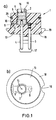
- Figure 1 shows an ignition device 1 with a receiving part 2 provided with a plastic body 13.
- Figure 1a shows a longitudinal section and
- Figure 1b shows a plan view.
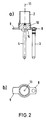
- FIGS. 2a, 2b show the identical receiving part 2, but without ignition kits and plastic bodies.
- the receiving part 2 is cylindrical and is made of metal (eg brass).
- a metal layer element 10 is inserted into the receiving part 2 at one end. In the area of the metal layer element 10, the receiving part 2 has a slight circumferential expansion.
- the ignition bridge is located on the metal layer element 10 and is connected in a electrically conductive manner to the housing of the receiving part 2 by a pole.
- a first contact pin 3 is riveted or welded into the first circumferential extension 8, advantageously soldered in, and extends parallel to the longitudinal axis 11 of the receiving part 2.
- a second contact pin 4 is inserted into the metal layer element 10 and lies on the lower end face of the metal layer element 10 with a flange 14 for limiting the depth of the insert. This second contact pin 4 is arranged on the longitudinal axis of the receiving part 2.
- a first ignition charge 5 and a second ignition charge 6 are arranged on the metal layer element 10 within the receiving part 2 (see FIG. 1a).
- the second ignition charge 6 is provided with a protective layer or cover 15.
- a crown 16 is arranged in the middle of the second ignition charge 6.
- the receiving part 2 is surrounded by a plastic body 13 made of polyamide. However, another plastic (e.g. polyether sulfone) or composite material can also be used.
- the receiving part 2 protrudes from the plastic body 13 with its upper end, the contact pins 3, 4 and the second circumferential extension 9 with its end.
- “Top” basically means the ignition side and "bottom” the electrical connection side.
- the second circumferential extension 9 projects close to the outer circumferential wall of the plastic body 13.
- a shoe 17 the contact pins 3, 4 adjacent, is arranged, which is used to attach known plugs or sockets. This connector shorts the two contact pins 3, 4 when the plug is not inserted.
- a flange 18 with a notch 19 is arranged above the shoe 17.
- the flange 18 is used to install the ignition device 1 in a pressure element housing (see FIG. 3).
- the ignition device 1 can be positioned with the notch 19 in the production process.
- an annular seal 20 designed as an O-ring is arranged on the outer wall of the plastic body 13.
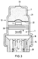
- FIGS. 1, 2 installed in a pressure element 12.
- the housing 7 of the pressure element 12 surrounds the ignition device 1 almost completely and lies against the outer wall of the plastic body 13.
- the housing 7 of the pressure element 12 forms a cavity in which a gas-generating charge 21 is arranged, which is protected on its lower side by a cover film 22.
- the housing 7 On the upper end face, the housing 7 has a predetermined breaking point 23 through which the released gas can leave the pressure element 12.
- the flange 18 already described above rests on an edge of the housing 7, a cone in a part 24 pressing the flange 18 and thus the ignition device sealingly against the housing 7.
- a known short-circuit socket 25 is shown, which short-circuits the two contact pins 3, 4 when the plug is not inserted.
- the lobe-shaped second circumferential extension 9 projects close to the housing 7 of the Pressure element 12 approach.
- a voltage flashover therefore takes place in a zone which is far away from the ignition sets 5, 6 in the ignition device 1. This arrangement thus provides protection against electrostatic discharge.
- the plastic body 13 has an annular recess 26 in the upper region of the receiving part 2.
- the receiving part 2 or the brass sleeve, in which the igniter 5, 6 are located is exposed in the upper region.
- This has the advantage that the mechanical impulse (shock load) is not introduced directly into the plastic body during ignition.
- the recess 26 extends almost over the entire length of the second ignition charge 6.
- the lower end of the recess 26 is formed with a radius.
- the pressure element described in Fig. 4 also shows an embodiment without a socket.
- the contacting between the contact pins 3, 4 and the supply line takes place by means of a soldered connection or clamp connection.
- the ring seal 20 shown in the figures also serves to protect the gas-generating charge 21 from moisture.
- High-strength plastics often have a high sensitivity to stress cracking.
- the receiving part 2 reduces the tensions in the plastic body caused by the pressing in of the ignition charges. This means that there are no long-term cracks in the plastic body.
Landscapes
- Engineering & Computer Science (AREA)
- General Engineering & Computer Science (AREA)
- Air Bags (AREA)
- Automotive Seat Belt Assembly (AREA)
- Ignition Installations For Internal Combustion Engines (AREA)
Abstract
Description
- Die Erfindung betrifft eine Anzündeinrichtung nach dem Oberbegriff des Anspruchs 1.
- Aus der DE-OS 36 06 364 ist ein elektrischer Zündbrückenträger zur Anzündung von Anzündsätzen, Verzögerungssätzen und pyrotechnischen Mischungen sowie zur Zündung von Primärzündstoffen und -sätzen bekannt. Der Zündbrückenträger bzw. diese Anzündeinrichtung weist ein metallisches Aufnahmeteil mit einer zylindrischen Ausnehmung auf, in der ein Keramikkörper eingebracht ist. Dieser Keramikkörper ist mit zwei Bohrungen versehen, in die jeweils ein massiver, rohrförmiger Kontaktstift fest und dicht eingepaßt ist. Auf der Anschlußseite ragen diese Kontaktstifte aus dem Keramikkörper heraus, während sie auf der Anzündseite über eine Zündbrücke miteinander verbunden sind. Angrenzend an die Zündbrücke ist ein Anzündsatz im Aufnahmeteil angeordnet. Bei der Zündung wird eine solch hohe Spannung an die Kontaktstifte gelegt, daß die Zündbrücke schlagartig verbrennt, wodurch der Anzündsatz gezündet wird.
- Derartige Anzündeinrichtungen können z.B. in Druckelemente für den Einsatz in Gurtstraffern, Schloßstraffern oder in Gurtaufrollern von Kraftfahrzeugen benutzt werden. Bei einem Unfall wird die Anzündeinrichtung durch einen Sensor ausgelöst, wodurch im Druckelement ein Gas erzeugt wird, welches z.B. einen Kolben bewegt. Der Kolben ist mit einem Seil am Gurtschloß bzw. mit einem Automatikgurtaufroller verbunden und strafft den Gurt.
- Nachteilig an der beschriebenen Anzündeinrichtung ist, daß durch von außen induzierte elektrische Felder eine elektrostatische Aufladung zwischen den Kontaktstiften und dem Gehäuse auftreten kann, die bei Entladung zum ungewollten Zünden des Anzündsatzes führen kann.
- Der Erfindung liegt daher die Aufgabe zugrunde, eine Anzündeinrichtung nach dem Oberbegriff des Anspruchs 1 derart weiterzubilden, daß bei elektrostatischen Entladungen zwischen den Kontaktstiften und dem Gehäuse kein Zünden des Anzündsatzes erfolgt.
- Erfindungsgemäß wird diese Aufgabe dadurch gelöst, daß das Aufnahmeteil mit Kunststoff umspritzbar und in ein Gehäuse einsetzbar ist, daß am Aufnahmeteil eine erste Umfangserweiterung vorgesehen ist, die mit dem ersten Kontaktstift elektrisch leitend verbunden ist, daß am Aufnahmeteil eine zweite Umfangserweiterung vorgesehen ist, die unter geringer Freistellung bis an das Gehäuse heranreichend ausbildbar ist und deren äußeres Ende nicht mit Kunststoff umspritzt ist.
- Dadurch, daß der erste Kontaktstift mit dem Aufnahmeteil leitend verbunden ist und das Aufnahmeteil über die zweite Umfangserweiterung bis an das Gehäuse heranreicht, findet eine etwaige elektrostatische Entladung zwischen dieser zweiten Umfangserweiterung und dem Gehäuse und damit weit weg von den Anzündsätzen statt. Durch den Kunststoffkörper ist das Aufnahmeteil sicher und leicht zu handhaben. Das Gehäuse ist elektrisch leitend ausgebildet.
- Vorteilhafterweise ist der erste Kontaktstift mit der ersten Umfangserweiterung durch Schweißung, Lötung bzw. Nietung verbunden. Hierdurch ist eine dauerhafte und optimale Verbindung erreicht.
- In bevorzugter erfindungsgemäßer Ausführungsform ist im Aufnahmeteil ein Metallschichtelement mit einer Zündbrücke angeordnet. Ein derartiges Metallschichtzündmittel bzw. Metallschichtelement ist Stand der Technik und z.B. in der DE-PS 20 20 016 beschrieben. Diese Metallschichtelemente sind kostengünstig herzustellen und liefern genau definierte Zündbrücken.
- Zweckmäßigerweise ist der zweite Kontaktstift im Metallschichtelement elektrisch leitend verankert. Dies kann z.B. durch Lötung geschehen. Die Zündbrücke befindet sich zwischen diesem zweiten Kontaktstift und dem Aufnahmeteil bzw. dem ersten Kontaktstift auf dem Metallschichtelement. Dieser erste Kontaktstift bildet somit die andere Anschlußelektrode.
- In bevorzugter Ausführungsform sind die erste und die zweite Umfangserweiterung in bezug auf die Längsachse des Aufnahmeteils diametral gegenüberliegend angeordnet.
- Zweckmäßigerweise ist das Aufnahmeteil zylinderförmig und aus Messing gefertigt und ist mit Polyamid umspritzt.
- In bevorzugter Ausführungsform ist die Anzündeinrichtung in ein mit einem gaserzeugenden Stoff geladenes Gehäuse eingebaut.
- In einer alternativen Ausgestaltung ist vorteilhafterweise zwischen Kunststoffkörper und Aufnahmeteil im Bereich der Anzündsätze eine ringförmige Ausnehmung vorgesehen. Durch diese Ausnehmung wird beim Zünden der mechanische Impuls nicht direkt in den Kunststoffmantel eingeleitet.
- Zweckmäßigerweise sind die Umfangserweiterungen an dem den Anzündsätzen entgegengesetzen Ende des Aufnahmeteils angeordnet. Die Umfangserweiterungen sind dabei bevorzugt laschen-, lappen-, stegförmig oder dergleichen ausgebildet und erstrecken sich im wesentlichen radial zur Längsachse des Aufnahmeteils. Es kann jedoch auch vorteilhaft sein, wenn die Umfangserweiterungen ineinander übergehen, d.h. einen Ringbund oder einen Ringflansch bilden.
- Weitere Merkmale der Erfindung ergeben sich aus den Zeichnungen, die nachfolgend beschrieben sind.
- Es zeigt:
- Fig.1
- eine erfindungsgemäße Anzündeinrichtung im Längsschnitt (Fig. 1a) und in Draufsicht (Fig. 1b),
- Fig. 2
- ein erfindungsgemäßes Aufnahmeteil mit Metallschichtelement im Längsschnitt (Fig. 2a) und im Querschnitt (Fig. 2b),
- Fig. 3
- ein Druckelement mit eingebauter Anzündeinrichtung,
- Fig. 4
- eine alternative erfindungsgemäße Anzündeinrichtung, wiederum eingebaut in ein Druckelement.
- Figur 1 zeigt eine Anzündeinrichtung 1 mit einem mit einem Kunststoffkörper 13 versehenen Aufnahmeteil 2. Figur 1a zeigt dabei einen Längsschnitt und Figur 1b eine Draufsicht. In den Figuren 2a, 2b ist das identische Aufnahmeteil 2, jedoch ohne Anzündsätze und Kunststoffkörper gezeigt.
- Das Aufnahmeteil 2 ist zylinderförmig ausgebildet und ist aus Metall (z.B. Messing) gefertigt. An seinem einen Ende ist ein Metallschichtelement 10 in das Aufnahmeteil 2 eingesetzt. Im Bereich des Metallschichtelementes 10 weist das Aufnahmeteil 2 eine geringfügige Umfangserweiterung auf. Auf dem Metallschichtelement 10 befindet sich die Zündbrücke, die mit einem Pol mit dem Gehäuse des Aufnahmeteils 2 elektrisch leitend verbunden ist. An seinem, dem Metallschichtelement zugewandten Ende des Aufnahmeteils 2 sind zwei in bezug auf die Längsachse 11 diametral gegenüberliegende, lappenförmige Umfangserweiterungen 8, 9 angeordnet. Diese Umfangserweiterungen 8, 9 erstrecken sich im rechten Winkel zum Gehäuse des Aufnahmeteils 2 und verlaufen an ihrer unteren Seite bündig mit der dort angeordneten unteren Stirnseite des Metallschichtelementes 10. Ein erster Kontaktstift 3 ist in die erste Umfangserweiterung 8 eingenietet bzw. angeschweißt, vorteilhafterweise eingelötet, und erstreckt sich parallel zur Längsachse 11 des Aufnahmeteils 2. Ein zweiter Kontaktstift 4 ist in das Metallschichtelement 10 eingesetzt und liegt mit einem Flansch 14 zur Begrenzung der Tiefe des Einschubes an der unteren Stirnseite des Metallschichtelementes 10 auf. Dieser zweite Kontaktstift 4 ist auf der Längsachse des Aufnahmeteils 2 angeordnet.
- Fig. 2b zeigt die Anordnung und Ausbildung der lappenförmigen Umfangserweiterungen 8, 9.
- Auf dem Metallschichtelement 10 innerhalb des Aufnahmeteils 2 ist ein erster Anzündsatz 5 und darüber ein zweiter Anzündsatz 6 angeordnet (siehe Fig. 1a). Der zweite Anzündsatz 6 ist mit einer Schutzschicht bzw. Abdeckung 15 versehen. In der Mitte des zweiten Anzündsatzes 6 ist eine Bombierung 16 angeordnet.
- Das Aufnahmeteil 2 ist mit einem Kunststoffkörper 13 aus Polyamid umgeben. Es kann jedoch auch ein anderer Kunststoff (z.B. Polyethersulfon) oder Verbundwerkstoff verwendet werden. Aus dem Kunststoffkörper 13 ragt das Aufnahmeteil 2 mit seinem oberen Ende, die Kontaktstifte 3, 4 und die zweite Umfangserweiterung 9 mit ihrem Ende heraus. Mit "oben" ist grundsätzlich die Anzündseite und mit "unten" die elektrische Anschlußseite verstanden.
- Die zweite Umfangserweiterung 9 ragt dabei bis nahe an die äußere Umfangswandung des Kunststoffkörpers 13 heran. Am unteren Ende des Kunststoffkörpers 13 ist ein Schuh 17, den Kontaktstiften 3, 4 benachbart, angeordnet, der zur Befestigung von bekannten Steckern bzw. Anschlußbuchsen dient. Diese Anschlußbuchse schließt bei nicht eingestecktem Stecker die beiden Kontaktstifte 3, 4 kurz.
- Oberhalb des Schuhs 17 ist ein Flansch 18 mit einer Kerbe 19 angeordnet. Der Flansch 18 dient zum Einbau der Anzündeinrichtung 1 in ein Druckelementgehäuse (siehe Fig. 3). Mit der Kerbe 19 läßt sich die Anzündeinrichtung 1 im Produktionsprozeß positionieren. Oberhalb der zweiten Umfangserweiterung 9 ist auf der Außenwand des Kunststoffkörpers 13 eine Ringdichtung 20 als O-Ring ausgebildet, angeordnet.
- Fig. 3 zeigt die Anzündeinrichtung 1 gemäß den Figuren 1, 2 eingebaut in ein Druckelement 12. Das Gehäuse 7 des Druckelementes 12 umgibt dabei die Anzündeinrichtung 1 nahezu vollständig und liegt an der Außenwandung des Kunststoffkörpers 13 an. Oberhalb der Anzündeinrichtung bildet das Gehäuse 7 des Druckelementes 12 einen Hohlraum, in dem eine gaserzeugende Ladung 21 angeordnet ist, die an ihrer unteren Seite durch eine Abdeckfolie 22 geschützt ist. An der oberen Stirnseite weist das Gehäuse 7 eine Sollbruchstelle 23 auf, durch die das freigesetzte Gas das Druckelement 12 verlassen kann. Der schon weiter oben beschriebene Flansch 18 liegt an einer Kante des Gehäuses 7 an, wobei ein Konus in einem Teil 24 den Flansch 18 und damit die Anzündeinrichtung dichtend gegen das Gehäuse 7 drückt. Am unteren Ende der Anzündeinrichtung ist eine bekannte Kurzschlußbuchse 25 gezeigt, die bei nicht eingestecktem Stecker die beiden Kontaktstifte 3, 4 kurzschließt. Erfindungsgemäß ragt die lappenförmige zweite Umfangserweiterung 9 bis nahe an das Gehäuse 7 des Druckelementes 12 heran. Bei elektrostatischen Aufladungen zwischen einem Kontaktstift 3, 4 und dem Gehäuse 7 findet daher ein Spannungsüberschlag in einer Zone statt, die weit von den Anzündsätzen 5, 6 in der Anzündeinrichtung 1 entfernt ist. Diese Anordnung bildet somit einen Schutz gegen elektrostatische Entladungen.
- Fig. 4 zeigt eine alternative Anzündeinrichtung. Die Alternative besteht darin, daß der Kunststoffkörper 13 im oberen Bereich des Aufnahmeteils 2 eine ringförmige Ausnehmung 26 aufweist. Hierdurch liegt das Aufnahmeteil 2 bzw. die Messinghülse, in der sich die Anzündsätze 5, 6 befinden, im oberen Bereich frei. Dies hat den Vorteil, daß beim Zünden der mechanische Impuls (Schockbelastung) nicht direkt in den Kunststoffkörper eingeleitet wird. Die Ausnehmung 26 erstreckt sich nahezu über die gesamte Länge des zweiten Anzündsatzes 6. Das untere Ende der Ausnehmung 26 ist mit einem Radius ausgebildet.
- Das in Fig. 4 beschriebene Druckelement zeigt weiterhin eine Ausführungsform ohne Anschlußbuchse. Hier erfolgt die Kontaktierung zwischen den Kontaktstiften 3, 4 und der Zuleitung mittels Lötverbindung bzw. Klemmverbindung.
- Die in den Figuren gezeigte Ringdichtung 20 dient auch als Schutz der gaserzeugenden Ladung 21 vor Feuchtigkeit.
- Hochfeste Kunststoffe haben oftmals eine hohe Spannungsrißempfindlichkeit. Das Aufnahmeteil 2 setzt die durch das Einpressen der Anzündsätze entstehenden Spannungen im Kunststoffkörper herab. Hierdurch entstehen keine Langzeitrisse im Kunststoffkörper.
Claims (13)
- Elektrische Anzündeinrichtung (1) mit einem metallischen Aufnahmeteil (2) für einen Zündwiderstand, einem ersten (3) und einem zweiten Kontaktstift (4) und zumindest einem Anzündsatz (5, 6), dadurch gekennzeichnet, daß das Aufnahmeteil (2) mit Kunststoff umspritzbar und in ein Gehäuse (7) einsetzbar ist, daß am Aufnahmeteil (2) eine erste Umfangserweiterung (8) vorgesehen ist, die mit dem ersten Kontaktstift (3) elektrisch leitend verbunden ist, daß am Aufnahmeteil (2) eine zweite Umfangserweiterung (9) vorgesehen ist, die unter geringer Freistellung bis an das Gehäuse (7) heranreichend ausbildbar ist und deren äußeres Ende nicht mit Kunststoff umspritzt ist.
- Anzündeinrichtung nach Anspruch 1, dadurch gekennzeichnet, daß der erste Kontaktstift (3) mit der ersten Umfangserweiterung (8) durch Schweißung, Nietung bzw. Lötung verbunden ist.
- Anzündeinrichtung nach Anspruch 1 oder 2, dadurch gekennzeichnet, daß im Aufnahmeteil (2) ein Metallschichtelement (10) mit einer Zündbrücke angeordnet ist.
- Anzündeinrichtung nach Anspruch 3, dadurch gekennzeichnet, daß der zweite Kontaktstift (4) im Metallschichtelement (10) elektrisch leitend verankert ist.
- Anzündeinrichtung nach einem der Ansprüche 1 bis 4, dadurch gekennzeichnet, daß die erste (8) und die zweite Umfangserweiterung (9) in bezug auf die Längsachse (11) des Aufnahmeteils (2) diametral gegenüberliegend angeordnet sind.
- Anzündeinrichtung nach einem der Ansprüche 1 bis 5, dadurch gekennzeichnet, daß das Aufnahmeteil (2) aus Messing gefertigt ist.
- Anzündeinrichtung nach einem der Ansprüche 1 bis 6, dadurch gekennzeichnet, daß das Aufnahmeteil (2) zylinderförmig ist.
- Anzündeinrichtung nach einem der Ansprüche 1 bis 7, dadurch gekennzeichnet, daß das Aufnahmeteil (2) mit Polyamid umspritzt ist.
- Anzündeinrichtung nach einem der Ansprüche 1 bis 8, dadurch gekennzeichnet, daß die Anzündeinrichtung (1) in ein mit einem gaserzeugenden Stoff geladenes Gehäuse (7) eingebaut ist.
- Anzündeinrichtung nach einem der Ansprüche 1 bis 9, dadurch gekennzeichnet, daß zwischen Kunststoffkörper (13) und Aufnahmeteil (2) im Bereich der Anzündsätze (5, 6) eine ringförmige Ausnehmung (26) vorgesehen ist.
- Anzündeinrichtung nach einem der Ansprüche 1 bis 10, dadurch gekennzeichnet, daß die Umfangserweiterungen (8, 9) an dem den Anzündsätzen (5, 6) entgegengesetzten Ende des Aufnahmeteils (2) angeordnet sind.
- Anzündeinrichtung nach einem der Ansprüche 1 bis 11, dadurch gekennzeichnet, daß die Umfangserweiterungen (8, 9) laschen-, lappen-, stegförmig oder dergleichen ausgebildet sind und sich im wesentlichen radial zur Längsachse (11) des Aufnahmeteils (2) erstrecken.
- Anzündeinrichtung nach einem der Ansprüche 1 bis 12, dadurch gekennzeichnet, daß die Umfangserweiterungen (8, 9) ineinander übergehen.
Applications Claiming Priority (2)
| Application Number | Priority Date | Filing Date | Title |
|---|---|---|---|
| DE4307774A DE4307774A1 (de) | 1993-03-12 | 1993-03-12 | Anzündeinrichtung |
| DE4307774 | 1993-03-12 |
Publications (2)
| Publication Number | Publication Date |
|---|---|
| EP0618424A1 true EP0618424A1 (de) | 1994-10-05 |
| EP0618424B1 EP0618424B1 (de) | 1997-06-04 |
Family
ID=6482555
Family Applications (1)
| Application Number | Title | Priority Date | Filing Date |
|---|---|---|---|
| EP94103456A Expired - Lifetime EP0618424B1 (de) | 1993-03-12 | 1994-03-08 | Anzündeinrichtung |
Country Status (5)
| Country | Link |
|---|---|
| US (1) | US5433147A (de) |
| EP (1) | EP0618424B1 (de) |
| JP (1) | JP3535559B2 (de) |
| DE (2) | DE4307774A1 (de) |
| ES (1) | ES2102707T3 (de) |
Cited By (4)
| Publication number | Priority date | Publication date | Assignee | Title |
|---|---|---|---|---|
| WO1998028167A1 (de) | 1996-12-24 | 1998-07-02 | Dynamit Nobel Gmbh Explosivstoff- Und Systemtechnik | Anzündelement, insbesondere für pyrotechnische mischungen |
| WO1999033685A1 (de) | 1997-12-23 | 1999-07-08 | Dynamit Nobel Gmbh | Pyrotechnischer gasgenerator |
| WO2018166720A1 (de) * | 2017-03-17 | 2018-09-20 | Takata AG | Zündeinrichtung eines gasgenerators eines airbagmodules für ein kraftfahrzeug |
| JP2022521101A (ja) * | 2019-02-27 | 2022-04-05 | オートリブ エー・エス・ピー・インク | 自動車安全装置のための開始剤 |
Families Citing this family (53)
| Publication number | Priority date | Publication date | Assignee | Title |
|---|---|---|---|---|
| US5596163A (en) * | 1993-08-25 | 1997-01-21 | Ems-Patvag Ag | Gas generator igniting capsule |
| US5670737A (en) * | 1993-12-14 | 1997-09-23 | Denel (Proprietary) Limited | Breaking up of rock and the like |
| FR2720493B1 (fr) * | 1994-05-31 | 1996-07-19 | Giat Ind Sa | Initiateur pyrotechnique. |
| US5621183A (en) * | 1995-01-12 | 1997-04-15 | Trw Inc. | Initiator for an air bag inflator |
| FR2732455B1 (fr) * | 1995-03-31 | 1997-06-13 | Davey Bickford | Initiateur electropyrotechnique, procede de realisation d'un tel initiateur et systeme de securite pour vehicule |
| US5556132A (en) * | 1995-04-13 | 1996-09-17 | Trw Inc. | Vehicle occupant restraint with auto ignition material |
| US5616881A (en) * | 1995-05-30 | 1997-04-01 | Morton International, Inc. | Inflator socket pin collar for integrated circuit initaitor with integral metal oxide varistor for electro-static discharge protections |
| US5631439A (en) * | 1995-06-07 | 1997-05-20 | Tracor Aerospace, Inc. | Multiple squib assembly |
| US5672841A (en) * | 1995-12-15 | 1997-09-30 | Morton International, Inc. | Inflator initiator with zener diode electrostatic discharge protection |
| US6662727B2 (en) | 1996-03-14 | 2003-12-16 | Dynamit Nobel Gmbh | Gas generator, in particular for belt tighteners |
| US5932832A (en) * | 1996-04-15 | 1999-08-03 | Autoliv Asp, Inc. | High pressure resistant initiator with integral metal oxide varistor for electro-static discharge protection |
| FR2747772B1 (fr) * | 1996-04-22 | 1999-08-06 | Livbag Snc | Initiateur a prise bifilaire autobloquante pour generateurs pyrotechniques de gaz |
| DE19617481A1 (de) * | 1996-05-02 | 1997-11-06 | Dynamit Nobel Ag | Elektrische Anzündeinrichtung |
| DE19639133A1 (de) * | 1996-07-31 | 1998-02-05 | Dynamit Nobel Ag | Elektrische Anzündeinrichtung mit einer elastischen Schicht zwischen dem Aufnahmeteil und dem Kunststoffkörper |
| FR2754050B1 (fr) * | 1996-10-01 | 1998-10-30 | Livbag Snc | Microgenerateur pyrotechnique de gaz a prise bifilaire bloquee |
| US6311621B1 (en) | 1996-11-01 | 2001-11-06 | The Ensign-Bickford Company | Shock-resistant electronic circuit assembly |
| US6079332A (en) * | 1996-11-01 | 2000-06-27 | The Ensign-Bickford Company | Shock-resistant electronic circuit assembly |
| US5988069A (en) * | 1996-11-12 | 1999-11-23 | Universal Propulsion Company, Inc. | Electric initiator having a sealing material forming a ceramic to metal seal |
| DE19847242C1 (de) * | 1998-10-14 | 2000-04-27 | Piepenbrock Pyrotechnik Gmbh | Elektrisch-mechanische Kupplung für elektrisch initiierbare Munition |
| GB2347485A (en) * | 1999-03-05 | 2000-09-06 | Breed Automotive Tech | Pretensioner |
| US6823796B1 (en) | 1999-10-14 | 2004-11-30 | Nippon Kayaku Kabushiki Kaisha | Gas generator |
| AT412127B (de) * | 1999-10-15 | 2004-09-27 | Hirtenberger Praez Stechnik Gm | Zünder für pyrotechnische ladungen |
| US7188567B1 (en) | 1999-11-12 | 2007-03-13 | Zodiac Automotive Us Inc. | Gas generation system |
| ATE270984T1 (de) * | 1999-11-22 | 2004-07-15 | Hirschmann Automotive Gmbh | Zünder |
| ATE257103T1 (de) * | 1999-11-22 | 2004-01-15 | Hirschmann Austria Gmbh | Zünder |
| DE10048287A1 (de) * | 2000-09-29 | 2002-04-25 | Audi Ag | Zündeinrichtung für eine Insassenschutzvorrichtung eines Kraftfahrzeuges |
| DE20020102U1 (de) | 2000-11-27 | 2001-04-05 | TRW Airbag Systems GmbH & Co. KG, 84544 Aschau | Pyrotechnische, gaserzeugende Vorrichtung |
| US6848365B2 (en) * | 2000-12-08 | 2005-02-01 | Special Devices, Inc. | Initiator with an internal sleeve retaining a pyrotechnic charge and methods of making same |
| US6578487B2 (en) * | 2000-12-08 | 2003-06-17 | Special Devices, Inc. | Pyrotechnic initiator with a narrowed sleeve retaining a pyrotechnic charge and methods of making same |
| DE10125354C2 (de) * | 2001-05-23 | 2003-11-27 | Nico Pyrotechnik | Zündvorrichtung für eine Insassenschutzeinrichtung eines Kraftfahrzeuges |
| US6467414B1 (en) | 2001-06-29 | 2002-10-22 | Breed Automotive Technology, Inc. | Ignitor with printed electrostatic discharge spark gap |
| US6672215B2 (en) * | 2001-10-17 | 2004-01-06 | Textron Systems Corporation | Constant output high-precision microcapillary pyrotechnic initiator |
| US6644206B2 (en) * | 2001-12-21 | 2003-11-11 | Trw Inc. | Electrically actuatable initiator with output charge |
| DE10236508A1 (de) * | 2002-02-09 | 2003-08-21 | Dynamit Nobel Ag | Pyrotechnische Zündkette mit einem Anzündträger aus Kunststoff mit integrierter Metalleinlage |
| US7162958B2 (en) * | 2002-05-17 | 2007-01-16 | Zodiac Automotive Us Inc. | Distributed charge inflator system |
| US7137341B2 (en) * | 2002-05-17 | 2006-11-21 | Zodiac Automotive Us Inc. | Distributed charge inflator system |
| DE102004004748A1 (de) * | 2003-03-08 | 2004-09-23 | Dynamit Nobel Ais Gmbh Automotive Ignition Systems | Glasdurchführung für einen pyroelektrischen Anzünder |
| DE102004010746A1 (de) * | 2003-04-30 | 2004-12-09 | Dynamit Nobel Ais Gmbh Automotive Ignition Systems | Gehäuse für ein pyromechanisches Trennelement mit integriertem Anzündelement |
| EP1473536B1 (de) * | 2003-04-30 | 2007-10-17 | Delphi Technologies, Inc. | Gehäuse für eine pyromechanische Trennvorrichtung mit integriertem Anzündelement |
| DE10323531B3 (de) * | 2003-05-24 | 2005-02-10 | Hilti Ag | Treibladungssatz, insbesondere für Bolzensetzgeräte |
| JP2005069666A (ja) * | 2003-08-06 | 2005-03-17 | Takata Corp | イニシエータ及びガス発生器 |
| DE10348382A1 (de) * | 2003-10-17 | 2005-05-25 | Daimlerchrysler Ag | Gasgenerator mit Ladungsableitstrecke |
| US7690303B2 (en) * | 2004-04-22 | 2010-04-06 | Reynolds Systems, Inc. | Plastic encapsulated energetic material initiation device |
| US20060260498A1 (en) * | 2005-04-05 | 2006-11-23 | Daicel Chemical Industries, Ltd. | Igniter assembly |
| DE102007014403B4 (de) * | 2007-03-26 | 2020-02-13 | Trw Airbag Systems Gmbh | Pyrotechnische Antriebseinheit sowie Verfahren zur Herstellung einer solchen Antriebseinheit |
| DE102008049652B4 (de) * | 2008-09-30 | 2023-12-14 | Zf Airbag Germany Gmbh | Gasgenerator mit bewegbarer Überströmöffnung |
| KR101782076B1 (ko) | 2008-09-30 | 2017-09-26 | 티알더블유 에어백 시스템즈 게엠베하 | 가스 발생기, 가스 발생기 제조 방법 및 가스 발생기를 구비하는 모듈 |
| US20120234839A1 (en) * | 2011-03-18 | 2012-09-20 | Autoliv Asp, Inc. | Compressed gas inflator with composite overwrap |
| US8397639B2 (en) * | 2011-04-08 | 2013-03-19 | Autoliv Asp, Inc. | Initiator with molded ESD dissipater |
| US9050944B1 (en) * | 2012-11-30 | 2015-06-09 | Tk Holdings Inc. | Gas generating system with initiator sub-assembly |
| US9939235B2 (en) * | 2013-10-09 | 2018-04-10 | Battelle Energy Alliance, Llc | Initiation devices, initiation systems including initiation devices and related methods |
| FR3012394B1 (fr) | 2013-10-25 | 2017-05-26 | Autoliv Dev | Interface de fixation pour actionneur pyrotechnique |
| FR3012595B1 (fr) * | 2013-10-25 | 2016-07-01 | Autoliv Dev | Allumeur pyrotechnique |
Citations (5)
| Publication number | Priority date | Publication date | Assignee | Title |
|---|---|---|---|---|
| GB1187373A (en) * | 1966-10-05 | 1970-04-08 | Graviner Colnbrook Ltd | Improvements in or relating to Explosive Cartridges |
| DE2020016A1 (de) * | 1970-04-24 | 1971-11-11 | Dynamit Nobel Ag | Metallschichtzuendmittel |
| US3971320A (en) * | 1974-04-05 | 1976-07-27 | Ici United States Inc. | Electric initiator |
| DE3606364A1 (de) * | 1986-02-27 | 1987-09-03 | Dynamit Nobel Ag | Elektrischer zuendbrueckentraeger zur anzuendung von anzuendsaetzen, verzoegerungssaetzen und pyrotechnischen mischungen sowie zur zuendung von primaerzuendstoffen und -saetzen und verfahren zu seiner herstellung |
| US5140906A (en) * | 1991-11-05 | 1992-08-25 | Ici Americas, Inc. | Airbag igniter having double glass seal |
Family Cites Families (9)
| Publication number | Priority date | Publication date | Assignee | Title |
|---|---|---|---|---|
| GB202416A (en) * | 1922-05-19 | 1923-08-20 | V L Oil Processes Ltd | Improvements in or relating to electric primers and vent sealing tubes |
| DE845466C (de) * | 1950-03-17 | 1952-07-31 | Dynamit Nobel Ag | Elektrischer Sicherheitszuender |
| US3180263A (en) * | 1963-04-08 | 1965-04-27 | Jr Nathan P Williams | Static electricity desensitizing device |
| JPS559301A (en) * | 1978-07-01 | 1980-01-23 | Nissan Motor | Connector for igniter |
| DE3425836A1 (de) * | 1984-07-13 | 1986-01-23 | Bayern-Chemie Gesellschaft für flugchemische Antriebe mbH, 8261 Aschau | Gasgenerator |
| US4745858A (en) * | 1986-09-26 | 1988-05-24 | Ireco Incorporated | Electric detonator with static electricity suppression |
| GB8926073D0 (en) * | 1989-11-17 | 1990-01-10 | Amp Gmbh | Shunting device for use in electrical connectors |
| CA2103510A1 (en) * | 1992-09-11 | 1994-03-12 | Morton International Inc. | Printed circuit bridge for an airbag inflator |
| JP2700100B2 (ja) * | 1993-05-28 | 1998-01-19 | 日本工機株式会社 | イグナイター |
-
1993
- 1993-03-12 DE DE4307774A patent/DE4307774A1/de not_active Withdrawn
-
1994
- 1994-03-08 DE DE59402965T patent/DE59402965D1/de not_active Expired - Lifetime
- 1994-03-08 EP EP94103456A patent/EP0618424B1/de not_active Expired - Lifetime
- 1994-03-08 ES ES94103456T patent/ES2102707T3/es not_active Expired - Lifetime
- 1994-03-14 US US08/209,881 patent/US5433147A/en not_active Expired - Lifetime
- 1994-03-14 JP JP04274994A patent/JP3535559B2/ja not_active Expired - Lifetime
Patent Citations (5)
| Publication number | Priority date | Publication date | Assignee | Title |
|---|---|---|---|---|
| GB1187373A (en) * | 1966-10-05 | 1970-04-08 | Graviner Colnbrook Ltd | Improvements in or relating to Explosive Cartridges |
| DE2020016A1 (de) * | 1970-04-24 | 1971-11-11 | Dynamit Nobel Ag | Metallschichtzuendmittel |
| US3971320A (en) * | 1974-04-05 | 1976-07-27 | Ici United States Inc. | Electric initiator |
| DE3606364A1 (de) * | 1986-02-27 | 1987-09-03 | Dynamit Nobel Ag | Elektrischer zuendbrueckentraeger zur anzuendung von anzuendsaetzen, verzoegerungssaetzen und pyrotechnischen mischungen sowie zur zuendung von primaerzuendstoffen und -saetzen und verfahren zu seiner herstellung |
| US5140906A (en) * | 1991-11-05 | 1992-08-25 | Ici Americas, Inc. | Airbag igniter having double glass seal |
Cited By (5)
| Publication number | Priority date | Publication date | Assignee | Title |
|---|---|---|---|---|
| WO1998028167A1 (de) | 1996-12-24 | 1998-07-02 | Dynamit Nobel Gmbh Explosivstoff- Und Systemtechnik | Anzündelement, insbesondere für pyrotechnische mischungen |
| WO1999033685A1 (de) | 1997-12-23 | 1999-07-08 | Dynamit Nobel Gmbh | Pyrotechnischer gasgenerator |
| WO2018166720A1 (de) * | 2017-03-17 | 2018-09-20 | Takata AG | Zündeinrichtung eines gasgenerators eines airbagmodules für ein kraftfahrzeug |
| JP2022521101A (ja) * | 2019-02-27 | 2022-04-05 | オートリブ エー・エス・ピー・インク | 自動車安全装置のための開始剤 |
| JP7117462B2 (ja) | 2019-02-27 | 2022-08-12 | オートリブ エー・エス・ピー・インク | 自動車安全装置のための開始剤 |
Also Published As
| Publication number | Publication date |
|---|---|
| US5433147A (en) | 1995-07-18 |
| JP3535559B2 (ja) | 2004-06-07 |
| JPH06300497A (ja) | 1994-10-28 |
| DE59402965D1 (de) | 1997-07-10 |
| DE4307774A1 (de) | 1994-09-15 |
| ES2102707T3 (es) | 1997-08-01 |
| EP0618424B1 (de) | 1997-06-04 |
Similar Documents
| Publication | Publication Date | Title |
|---|---|---|
| EP0618424B1 (de) | Anzündeinrichtung | |
| DE2830552C2 (de) | Kurzschlußsicherung für elektrische Zünder | |
| DE4002088C1 (de) | ||
| DE69833228T2 (de) | Brückenzünder | |
| DE69308004T2 (de) | Pyrotechnische elektrische Anzünder | |
| DE69834939T2 (de) | Elektrisches Zündelement | |
| DE69614984T2 (de) | Zünder für Aufblasvorrichtung mit Zenerdiode zum Schutz von elektrostatischen Entladungen | |
| DE3022654C2 (de) | Schneidvorrichtung für Rohrleitungen | |
| DE3447478A1 (de) | Pyrotechnische zuendkapsel mit koaxialstecker | |
| DE1001160B (de) | Elektrischer Aufschlagzuender fuer Geschosse | |
| DE2245308A1 (de) | Elektrisches zuendmittel | |
| WO2000040920A1 (de) | Auslöseeinheit zur initiierung pyrotechnischer elemente mit zweiteiliger kapsel | |
| DE60019995T2 (de) | Strammvorrichtung mit Verbindung zur Erdung des Zündergehaüses | |
| DE2913231A1 (de) | Elektrische sicherheitszuendeinrichtung | |
| DE2655758A1 (de) | Pyrotechnische vorrichtung und verfahren zu deren herstellung | |
| EP0883789B1 (de) | Gasgenerator, insbesondere für gurtstraffer | |
| DE2355255C2 (de) | Anzündvorrichtung für Artillerietreibladungen | |
| DE19820757B4 (de) | Zündpille für einen Airbag | |
| DE19620204A1 (de) | Anschlußeinrichtung für eine Batterieklemme | |
| DE19514282B4 (de) | Elektrischer Sprengzünder | |
| DE112022002503T5 (de) | Zünderanordnung und Gaserzeugungsvorrichtung | |
| RU2196954C1 (ru) | Электровоспламенительное устройство | |
| DE2655886C2 (de) | Elektrischer Zünder für Geschosse | |
| DE19962590A1 (de) | Steuerungsmodul für Auslöseeinheiten zur Initiierung pyrotechnischer Elemente | |
| DE3872818T2 (de) | Geschossboden fuer eine mit einem elektrischen zuender versehene grosskalibermunition. |
Legal Events
| Date | Code | Title | Description |
|---|---|---|---|
| PUAI | Public reference made under article 153(3) epc to a published international application that has entered the european phase |
Free format text: ORIGINAL CODE: 0009012 |
|
| AK | Designated contracting states |
Kind code of ref document: A1 Designated state(s): DE ES FR GB IT SE |
|
| 17P | Request for examination filed |
Effective date: 19950314 |
|
| GRAG | Despatch of communication of intention to grant |
Free format text: ORIGINAL CODE: EPIDOS AGRA |
|
| RAP1 | Party data changed (applicant data changed or rights of an application transferred) |
Owner name: DYNAMIT NOBEL GMBH EXPLOSIVSTOFF- UND SYSTEMTECHNI |
|
| 17Q | First examination report despatched |
Effective date: 19960912 |
|
| GRAH | Despatch of communication of intention to grant a patent |
Free format text: ORIGINAL CODE: EPIDOS IGRA |
|
| GRAH | Despatch of communication of intention to grant a patent |
Free format text: ORIGINAL CODE: EPIDOS IGRA |
|
| GRAA | (expected) grant |
Free format text: ORIGINAL CODE: 0009210 |
|
| ITF | It: translation for a ep patent filed | ||
| AK | Designated contracting states |
Kind code of ref document: B1 Designated state(s): DE ES FR GB IT SE |
|
| GBT | Gb: translation of ep patent filed (gb section 77(6)(a)/1977) |
Effective date: 19970606 |
|
| REF | Corresponds to: |
Ref document number: 59402965 Country of ref document: DE Date of ref document: 19970710 |
|
| REG | Reference to a national code |
Ref country code: ES Ref legal event code: FG2A Ref document number: 2102707 Country of ref document: ES Kind code of ref document: T3 |
|
| ET | Fr: translation filed | ||
| PLBE | No opposition filed within time limit |
Free format text: ORIGINAL CODE: 0009261 |
|
| STAA | Information on the status of an ep patent application or granted ep patent |
Free format text: STATUS: NO OPPOSITION FILED WITHIN TIME LIMIT |
|
| 26N | No opposition filed | ||
| REG | Reference to a national code |
Ref country code: GB Ref legal event code: IF02 |
|
| REG | Reference to a national code |
Ref country code: GB Ref legal event code: 732E |
|
| REG | Reference to a national code |
Ref country code: FR Ref legal event code: TP |
|
| REG | Reference to a national code |
Ref country code: ES Ref legal event code: PC2A |
|
| PGFP | Annual fee paid to national office [announced via postgrant information from national office to epo] |
Ref country code: SE Payment date: 20110311 Year of fee payment: 18 Ref country code: FR Payment date: 20110317 Year of fee payment: 18 Ref country code: IT Payment date: 20110312 Year of fee payment: 18 |
|
| PGFP | Annual fee paid to national office [announced via postgrant information from national office to epo] |
Ref country code: ES Payment date: 20110414 Year of fee payment: 18 Ref country code: GB Payment date: 20110302 Year of fee payment: 18 |
|
| REG | Reference to a national code |
Ref country code: DE Ref legal event code: R082 Ref document number: 59402965 Country of ref document: DE Representative=s name: MUELLER, KARL-ERNST, DIPL.-ING. DR.-ING., DE Ref country code: DE Ref legal event code: R082 Ref document number: 59402965 Country of ref document: DE Representative=s name: KARL-ERNST MUELLER, DE |
|
| REG | Reference to a national code |
Ref country code: FR Ref legal event code: TP Owner name: AUTOLIV DEVELOPMENT AB, SE Effective date: 20111123 |
|
| PGFP | Annual fee paid to national office [announced via postgrant information from national office to epo] |
Ref country code: DE Payment date: 20120111 Year of fee payment: 19 |
|
| REG | Reference to a national code |
Ref country code: SE Ref legal event code: EUG |
|
| PG25 | Lapsed in a contracting state [announced via postgrant information from national office to epo] |
Ref country code: SE Free format text: LAPSE BECAUSE OF NON-PAYMENT OF DUE FEES Effective date: 20120309 |
|
| GBPC | Gb: european patent ceased through non-payment of renewal fee |
Effective date: 20120308 |
|
| REG | Reference to a national code |
Ref country code: FR Ref legal event code: ST Effective date: 20121130 |
|
| PG25 | Lapsed in a contracting state [announced via postgrant information from national office to epo] |
Ref country code: GB Free format text: LAPSE BECAUSE OF NON-PAYMENT OF DUE FEES Effective date: 20120308 Ref country code: FR Free format text: LAPSE BECAUSE OF NON-PAYMENT OF DUE FEES Effective date: 20120402 |
|
| PG25 | Lapsed in a contracting state [announced via postgrant information from national office to epo] |
Ref country code: IT Free format text: LAPSE BECAUSE OF NON-PAYMENT OF DUE FEES Effective date: 20120308 |
|
| REG | Reference to a national code |
Ref country code: ES Ref legal event code: FD2A Effective date: 20130710 |
|
| PG25 | Lapsed in a contracting state [announced via postgrant information from national office to epo] |
Ref country code: ES Free format text: LAPSE BECAUSE OF NON-PAYMENT OF DUE FEES Effective date: 20120309 |
|
| REG | Reference to a national code |
Ref country code: DE Ref legal event code: R119 Ref document number: 59402965 Country of ref document: DE Effective date: 20131001 |
|
| PG25 | Lapsed in a contracting state [announced via postgrant information from national office to epo] |
Ref country code: DE Free format text: LAPSE BECAUSE OF NON-PAYMENT OF DUE FEES Effective date: 20131001 |