EP0618460B1 - Système pour la détermination de la position et/ou de la vitesse d'un objet en utilisant un marqueur d'identification à ondes de surface, à utiliser notamment dans les systèmes de chargement et déplacement - Google Patents
Système pour la détermination de la position et/ou de la vitesse d'un objet en utilisant un marqueur d'identification à ondes de surface, à utiliser notamment dans les systèmes de chargement et déplacement Download PDFInfo
- Publication number
- EP0618460B1 EP0618460B1 EP94104638A EP94104638A EP0618460B1 EP 0618460 B1 EP0618460 B1 EP 0618460B1 EP 94104638 A EP94104638 A EP 94104638A EP 94104638 A EP94104638 A EP 94104638A EP 0618460 B1 EP0618460 B1 EP 0618460B1
- Authority
- EP
- European Patent Office
- Prior art keywords
- identification
- distance
- objects
- antenna
- identification mark
- Prior art date
- Legal status (The legal status is an assumption and is not a legal conclusion. Google has not performed a legal analysis and makes no representation as to the accuracy of the status listed.)
- Expired - Lifetime
Links
Images

Classifications
-
- G—PHYSICS
- G01—MEASURING; TESTING
- G01S—RADIO DIRECTION-FINDING; RADIO NAVIGATION; DETERMINING DISTANCE OR VELOCITY BY USE OF RADIO WAVES; LOCATING OR PRESENCE-DETECTING BY USE OF THE REFLECTION OR RERADIATION OF RADIO WAVES; ANALOGOUS ARRANGEMENTS USING OTHER WAVES
- G01S13/00—Systems using the reflection or reradiation of radio waves, e.g. radar systems; Analogous systems using reflection or reradiation of waves whose nature or wavelength is irrelevant or unspecified
- G01S13/74—Systems using reradiation of radio waves, e.g. secondary radar systems; Analogous systems
- G01S13/75—Systems using reradiation of radio waves, e.g. secondary radar systems; Analogous systems using transponders powered from received waves, e.g. using passive transponders, or using passive reflectors
- G01S13/751—Systems using reradiation of radio waves, e.g. secondary radar systems; Analogous systems using transponders powered from received waves, e.g. using passive transponders, or using passive reflectors wherein the responder or reflector radiates a coded signal
- G01S13/755—Systems using reradiation of radio waves, e.g. secondary radar systems; Analogous systems using transponders powered from received waves, e.g. using passive transponders, or using passive reflectors wherein the responder or reflector radiates a coded signal using delay lines, e.g. acoustic delay lines
-
- B—PERFORMING OPERATIONS; TRANSPORTING
- B66—HOISTING; LIFTING; HAULING
- B66C—CRANES; LOAD-ENGAGING ELEMENTS OR DEVICES FOR CRANES, CAPSTANS, WINCHES, OR TACKLES
- B66C13/00—Other constructional features or details
- B66C13/18—Control systems or devices
- B66C13/46—Position indicators for suspended loads or for crane elements
-
- G—PHYSICS
- G01—MEASURING; TESTING
- G01S—RADIO DIRECTION-FINDING; RADIO NAVIGATION; DETERMINING DISTANCE OR VELOCITY BY USE OF RADIO WAVES; LOCATING OR PRESENCE-DETECTING BY USE OF THE REFLECTION OR RERADIATION OF RADIO WAVES; ANALOGOUS ARRANGEMENTS USING OTHER WAVES
- G01S5/00—Position-fixing by co-ordinating two or more direction or position line determinations; Position-fixing by co-ordinating two or more distance determinations
- G01S5/02—Position-fixing by co-ordinating two or more direction or position line determinations; Position-fixing by co-ordinating two or more distance determinations using radio waves
- G01S5/0247—Determining attitude
Definitions
- the present invention relates to a detection system the relative position and / or the relative movement two objects to each other, by means of radio-technical location using passive surface wave identification marks (ID tag).
- ID tag passive surface wave identification marks
- the system according to the invention is in particular for operating areas with loading and handling with Chargers and / or hoists for moving loads as such relevant objects.
- loads / objects are special Containers, whose transshipment with e.g. Crane systems using of the system according to the invention, at least to the extent that it is automatic is feasible that the accuracy and precision of the Controlling the chargers and objects to each other no longer depends on the skill of the people involved.
- ID tags use the one on a piezoelectric substrate body existing surface wave stripe structure with an electromechanical / mechanoelectric Interdigital converter structure and a reflector structure and one to the transducer structure connected input / output antenna.
- ID tags / identification marks are passive working elements with electrical input and output, but acoustomechanical Functionality. To function as intended, need they don't have their own power supply. They are extraordinary in construction robust and work due to their hermetic encapsulation practically completely independent of dirt. she are therefore suitable even for very rough technical operations in even a hostile environment.
- Such identification marks have at the remote-queryable built by Siemens The toll system of the city's highway system Oslo large-scale application found. They are very inexpensive to manufacture, do not require any maintenance in operation and are extremely durable without losing its precision.
- Such passive identification marks are used as follows: With an interrogation device, radio pulses in the decimeter wave range are continuously transmitted via its transmitting antenna. In the range of the transmitter, this identification mark receives this radio pulse (burst) by means of its input antenna, from which the received pulse signal is fed to the converter already mentioned. With the reflector present in the identification mark, a characteristic pulse sequence pattern is impressed on the surface acoustic wave generated by the transducer in the reflector. The pattern can be determined or determined by the chosen structure of the reflector. With conventional identification marks of this type, the variety, ie the number of possible codings, is a multiple of 10 9 possibilities.
- an electromagnetic (response) signal is sent back to the antenna (previously used as a transmitting antenna), which is now used as the receiving antenna of the evaluation device, via the antenna of the identification mark.
- Impulse response consists of one of the specified coding the pulse sequence corresponding to the reflector structure with a Carrier frequency that is either equal to the transmit frequency or their deviation from the transmission frequency a further signal information is how this is described below becomes.
- the impulse response is advantageously the identification mark delayed by approximately 1 ⁇ s compared to the transmission pulse. Any echoes from the nearby area, which are much earlier can receive the receiving antenna of the evaluation device can easily be hidden in time. Interference from Echo signals are not a problem here. Otherwise, the Query distance advantageously limited and limited, so that problems with spatially adjacent radio / high-frequency systems are at least easily manageable.
- a system for determining the distance of objects is known from WO 90/15343, with which the removal of a passive SAW transponder attached to the object (Identification mark with surface wave component) in the detection cone a query signal can be determined.
- a charging device with a sensor arrangement is known from WO 90/09336, which determines the relative position of a container to the loading device.
- Several sensors on the charging harness each measure by reflecting one Send signal the distance to the container, so that the positioning of the Loading harness can be controlled automatically.
- the object of the present invention is to use identification marks to provide an alternative system and method, with which the loading business can be automated and / or carried out with greater precision is when this is usually human-executable.
- the present invention relates to advantageous use such passively working surface identification marks for contactless identification and for recognizing positions and / or movement speeds of e.g. Containers or the like, as they are used regularly in transportation Find.
- identification marks as described above (with surface wave structure and input / output antenna) on featured positions e.g. to place such containers on their outer surface, e.g. to stick, to attach or the like can also vehicles or their cargo areas with each one or more such identification marks his.
- the system according to the invention is essentially also possible about how in a sensible way with such in principle already known identification marks worked advantageously and which evaluations are to be provided or carried out are e.g. the loading gear of a crane, by the crane operator roughly controlled, with high precision automatically on e.g. the To bring the loading eyelets of a container down to the cm, and this even with relatively poor visibility, e.g. in night mode.
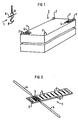
- FIG. 1 shows, designated C, a container with eyelets 7 for attaching a crane hook 8 to a loading harness L. With 1 and 1 'two identification marks are designated as they will be described in more detail below. With 9 it is Transmitting / receiving antenna of an interrogation / evaluation device.
- 1 is an identification tag also known as an ID tag shown schematically.
- substrate body made preferably piezoelectric strongly coupling material such as lithium niobate, tantalate and the like.
- Striped structure On the surface of the with 2 designated substrate body made preferably piezoelectric strongly coupling material such as lithium niobate, tantalate and the like, there is a photolithographically applied one Striped structure.
- the portion of this stripe structure denoted by 3 is the digital converter, at its electrical connections the dipoles of antenna 4 are connected.
- With 5 is the stripe structure of the reflector.
- a in practice, such reflector structure 5 has several 100 in periodically arranged reflector strips, from which the large number of coding options can be seen.
- Figure 3 shows that in the impulse response of the identification mark 1 contained pulse train 10 (envelope), which is the response of the Coding of the reflector structure 5 on a received burst 11 is.
- pulse train 10 envelope
- the change in the time interval between the burst pulse 11 and the response pulses 10, starting from a predetermined one Value for a known distance is a reference for a change in the spatial distance between the antennas 9 and 4 of the two objects, e.g. between the charging harness L and the location of the responding identification marks 1 or 1 '.
- the amplitude levels of the pulse peaks 10 and 11 are not shown to scale to one another.
- the invention relates to the detection of the relative position two objects to each other, namely one on the storage bin parked container C as e.g. one object and one Loading harnesses L of a crane as e.g. the other object.
- the container as a rule stands still and only the loading gear is moved.
- a further development of the invention relates to detection of the movement, specifically the speed of movement of two objects relative to each other.
- the evaluation takes place under Use of the resulting speed values, e.g. alone of the loading gear when the container is stationary and parked.
- both evaluations can be used.
- one object e.g. the Containers to affix several identification marks.
- This several identification marks are to be placed in such a way that they mark relevant locations of the container. For example is a (respective) identification mark near an eyelet 7 attached for hooking the load harness.
- a (respective) identification mark near an eyelet 7 attached for hooking the load harness.
- the signal processing knowing the pattern, i. h. must know which parts of the container this is by definition are. If several identification marks 1, 1 'are provided, so they advantageously have different coding, so that they are distinguishable for the evaluation device are recognizable.
- identification marks 1, 1 'with different Coding also with different forms or assembly means to provide.
- the shot on object C has the corresponding form.
- these two Identification marks base plates, with their rectangular Form each corner is cut off. With one or the like measure can be achieved that a respective identification mark with a specific coding unmistakable only on an optionally specified one Can be attached to the container.
- the antenna 9 of the query / evaluation device for transmitting the Query pulse signal and attached to receive the pulse signal.
- the (straight) distance can be measured with just one measurement between the antenna 9 and the identification mark 1, 1 'can be roughly determined. This current distance results from the time delay that the impulse response is due to back and forth distance distance required. Become the distances from the transmitting / receiving antenna 9 at least three identification marks attached to the container at predetermined locations (with different coding) measured, can the position of the antenna 9, i.e. the position of the lifting gear, clearly determined in relation to the container become. So that the lifting gear can automatically on the Containers are brought, and also on the correct container if taken into account in the evaluation which container which encodings of its individual Has identification marks.
- the relative speed of the two objects to one another result in Doppler frequency shifts in the carrier frequency of the impulse response signal.
- the received carrier frequency is the impulse response at the transmission frequency f S f S +/- ⁇ f .
- the Doppler frequency shift ⁇ f is very small and the phase shift ⁇ is evaluated for evaluation.
- ⁇ 2 . 2 ⁇ ⁇ r / ⁇ where ⁇ is the wavelength of the transmission frequency of the interrogation pulse.
- the factor 2 in turn is based on the double passage of the distance / r /.
- Another evaluation measure according to the invention is to determine the course and the sign of the Doppler speed and the change in the phase angle ⁇ and to use them to determine the relative position of this antenna and the identification mark.
- the transmitting / receiving antenna 9 moving at a speed v at a distance past the identification mark 1 queried in each case can be seen from the distance ⁇ x of the antenna on the path of the antenna between two measurements and the change in the distance ⁇ r between this antenna 9 and determine the distance a from the identification mark in which this antenna is moved past the identification mark on its path of movement.
- This distance variable a defined in this way cannot be determined by evaluating the Doppler shift, because this distance a is directed perpendicular to the relative movement of the antenna, that is to say the Doppler shift at this point is zero.
- the calculation of the intersection of the radiation of the interrogation pulses emitted by the movement path 21 at the angle ⁇ is carried out using the following two equations for the unknown a (with the unknown location coordinate x 0 on the path 21).
- a [r 1 2nd - (x 0 - x 1 ) 2nd ] 1/2
- a [r 2nd 2nd - (x 0 - x 2nd ) 2nd ] 1/2
- the distance a of FIG. 4 can thus be determined at a known speed v.
- the speed v at which the transmitting / receiving antenna 20, ie the lifting gear, is moved is known or can be determined from the movement by the computer.
- the point x 0 ie the point of the smallest distance a, of the movement path 2 of the charging device, or the antenna 9, which runs past the identification mark 1, of the relevant identification mark 1 is the one at which the Doppler frequency shift of the frequency of the carrier of the impulse response is the sign changes (ie as already stated above the Doppler frequency shift goes through zero).
- this point can usually only be determined with limited accuracy because the measure of the frequency shift in the vicinity of this point x 0 with the smallest distance a approaches the value zero with a small gradient.
- the speed at which the z. B. lifting gear is moved can be set using sensors (tachometers) in the system determine or is using ultrasonic or microwave sensors (e.g. towards another fixed location, e.g. one determine the supports of the portal for a portal crane, the possibly existing speed of movement on the ground on your part is determined tachometrically.
- the speed at that moves the antenna attached to the lifting gear also from the asymptote of the course of the Doppler frequency shift be determined because at a great distance from the queried identification mark from the Doppler shift derived speed equals true speed of the lifting gear.
- movement is common of the lifting gear is an accelerated movement.
- the Speed can then be taken from the mean between the two asymptotically determined speed values determined the asymptotic value before driving past and the one after driving past the requested one Identification mark.
- the lifting gear i.e. the Transmitting / receiving antenna of the system
- the same identification mark query and accordingly the impulse response received at two different locations in the room and the corresponding different terms or Doppler shift and evaluate their course and the like.
- the steepness of the Moving the input / output antenna 9 past the identification mark 1 detectable change in Doppler frequency also a measure of the distance of the web from the identification mark. The greater the slope, the lower this distance. The same can be achieved if you use the lifting gear on two parallel paths at a distance from each other lets the relevant identification tag pass.
- Uniqueness can also be achieved by (practically simultaneously) several on the container attached identification marks with different coding be queried. Knowledge about the approximate location of the identification mark to be queried and their installation. Likewise, plausible Assumptions are used for simplification, e.g. that the container is on the ground. Further a priori and learned knowledge can be used with fuzzy logic.
- this is an object a container and the other object one Hoist.
- this does not limit the general applicability the invention on two other objects, the z. B. an object and a fork lift truck, the z. B. the crane hook 8 hanging charge (with the transmit / receive antenna 9 preferably is attached to the hook) and a loading area of a transport vehicle or the hatch of a ship's storage space as a loading area or, e.g. the eye of the drawbar of a standing, to be coupled and the trailer coupling of the shunting Can be towing vehicle.
Landscapes
- Engineering & Computer Science (AREA)
- Radar, Positioning & Navigation (AREA)
- Remote Sensing (AREA)
- Automation & Control Theory (AREA)
- Mechanical Engineering (AREA)
- Computer Networks & Wireless Communication (AREA)
- Physics & Mathematics (AREA)
- General Physics & Mathematics (AREA)
- Radar Systems Or Details Thereof (AREA)
- Control And Safety Of Cranes (AREA)
- Machine Tool Sensing Apparatuses (AREA)
Claims (12)
- Système de détermination de la distance relative de deux objets l'un par rapport à l'autre au moyen d'une localisation par une technique radio en utilisant un marqueur d'identification passif (ID-Tag) (1), qui a une antenne d'émission et de réception (4), dans lequel le marqueur d'identification (1) est un composant à ondes de surface ayant une structure de convertisseur et avec une structure de réflecteur,
caractérisé par le fait que, pour la détermination univoque de la position relative entre deux objets, plusieurs marqueurs d'identification (1) ayant des codages différents sont disposés à distance les uns des autres sur l'un des deux objets à des endroits prescrits de celui-ci et qu'une antenne d'émission et de réception (9) est disposée sur le deuxième objet à un endroit prescrit de celui-ci, antenne par l'intermédiaire de laquelle des impulsions radio (11) peuvent être émises et des signaux de réponse impulsionnelle peuvent être reçus et qui est reliée à un appareil d'interrogation et d'évaluation, l'appareil d'interrogation et d'évaluation étant conçu de telle sorte que, à partir du signal de réponse impulsionnelle (10) reçu, une distance instantanée (r) entre l'antenne d'émission et de réception (9) de l'appareil d'interrogation et les marqueurs d'identification (1) peut être déterminée à partir des temps de parcours des distances entre les antennes et/ou à partir de la phase, rapportée à une phase de référence, et que, la position du premier objet par rapport au deuxième objet peut en être déterminée. - Système selon la revendication 1, dans lequel, pour la détection de position, trois marqueurs d'identification (1) sont disposés sur le premier objet à une certaine distance les uns des autres à des endroits prescrits de l'objet, lesquels marqueurs d'identification se distinguent par le codage de leurs signaux de réponse impulsionnelle.
- Système selon la revendication 1 ou 2, dans lequel des marqueurs d'identification ayant des codages différents sont disposés sur l'objet selon une certaine répartition correspondant à un modèle prédéterminé.
- Système selon la revendication 3, dans lequel un marqueur d'identification d'un certain codage comporte des moyens de forme/montage qui lui sont associés et par lesquels un marqueur d'identification de ce genre a un agencement mécanique différent de celui de marqueurs d'identification d'autres codages.
- Procédé de détermination de la distance relative de deux objets l'un par rapport à l'autre au moyen d'une localisation par une technique radio en utilisant un marqueur d'identification passif (ID-Tag) (1), qui a une antenne d'émission et de réception (4), dans lequel le marqueur d'identification (1) est un composant à ondes de surface ayant une structure de convertisseur et une structure de réflecteur,
caractérisé par le fait que, pour la détermination univoque de la position relative entre deux objets, plusieurs marqueurs d'identification (1) ayant des codages différents sont disposés à distance les uns des autres sur l'un des deux objets à des endroits prescrits de celui-ci et qu'une antenne d'émission et de réception (9) est disposée sur le deuxième objet à un endroit prescrit de celui-ci, antenne par l'intermédiaire de laquelle des impulsions radio (11) peuvent être émises et des signaux de réponse impulsionnelle peuvent être reçus et qui est reliée à un appareil d'interrogation et d'évaluation, l'appareil d'interrogation et d'évaluation étant conçu de telle sorte que, à partir du signal de réponse impulsionnelle (10) reçu, une distance instantanée (r) entre l'antenne d'émission et de réception (9) de l'appareil d'interrogation et les marqueurs d'identification (1) peut être déterminée à partir des temps de parcours pour les distances entre les antennes et/ou à partir de la phase, rapportée à une phase de référence, et que la position du premier objet par rapport au deuxième objet peut en être déterminée. - Procédé selon la revendication 5, dans lequel on détermine à partir d'au moins deux signaux de réponse impulsionnelle interrogés successivement dans le temps la vitesse du déplacement de deux objets l'un par rapport à l'autre.
- Procédé selon la revendication 5 ou 6, dans lequel on utilise l'allure du décalage de fréquence de Doppler pour la détermination de la vitesse sur la trajectoire et/ou pour la détermination du point sur la trajectoire ayant la plus petite distance au marqueur d'identification interrogé.
- Utilisation d'un système selon l'une des revendications 1 à 4 ou d'un procédé selon l'une des revendications 5 à 7 pour saisir, manoeuvrer et/ou transborder un conteneur constituant le premier objet au moyen d'un dispositif de préhension et de suspension constituant l'autre objet.
- Utilisation d'un système selon l'une des revendications 1 à 4 ou d'un procédé selon l'une des revendications 5 à 7 pour la détection de la position et de l'orientation d'une surface de chargement constituant le premier objet et d'un appareil de chargement constituant l'autre objet.
- Utilisation d'un système selon l'une des revendications 1 à 4 ou d'un procédé selon l'une des revendications 5 à 7 pour l'attelage d'un véhicule immobile constituant le premier objet à un véhicule à déplacer constituant l'autre objet.
- Utilisation d'un système selon l'une des revendications 1 à 5 ou d'un procédé selon l'une des revendications 6 à 10, avec un chariot élévateur à fourche constituant le premier objet et avec un objet à prendre avec le chariot élévateur à fourche et constituant l'autre objet.
- Utilisation d'un système selon l'une des revendications 1 à 5 ou d'un procédé selon l'une des revendications 6 à 10 pour le rapprochement commandé automatiquement des deux objets l'un par rapport à l'autre.
Applications Claiming Priority (2)
| Application Number | Priority Date | Filing Date | Title |
|---|---|---|---|
| DE4310609 | 1993-03-31 | ||
| DE4310609 | 1993-03-31 |
Publications (3)
| Publication Number | Publication Date |
|---|---|
| EP0618460A2 EP0618460A2 (fr) | 1994-10-05 |
| EP0618460A3 EP0618460A3 (en) | 1995-08-16 |
| EP0618460B1 true EP0618460B1 (fr) | 2000-03-01 |
Family
ID=6484414
Family Applications (1)
| Application Number | Title | Priority Date | Filing Date |
|---|---|---|---|
| EP94104638A Expired - Lifetime EP0618460B1 (fr) | 1993-03-31 | 1994-03-23 | Système pour la détermination de la position et/ou de la vitesse d'un objet en utilisant un marqueur d'identification à ondes de surface, à utiliser notamment dans les systèmes de chargement et déplacement |
Country Status (3)
| Country | Link |
|---|---|
| EP (1) | EP0618460B1 (fr) |
| AT (1) | ATE190135T1 (fr) |
| DE (1) | DE59409160D1 (fr) |
Families Citing this family (9)
| Publication number | Priority date | Publication date | Assignee | Title |
|---|---|---|---|---|
| DE19631623C2 (de) | 1996-08-05 | 1999-01-14 | Siemens Ag | Vorrichtung zur Bestimmung der Position einer Lastaufnahme bei Hebezeugen |
| DE19946204A1 (de) * | 1999-09-27 | 2001-03-29 | Siemens Ag | Meßeinrichtung zur Positionsbestimmung von Lastaufnahmemitteln bei Hebezeugen |
| DE10024474A1 (de) * | 2000-05-18 | 2001-11-29 | Siemens Ag | Verfahren und Vorrichtung zur drahtlosen Positions- und/oder Lagebestimmung wenigstens eines Objektes |
| DE10026075B4 (de) * | 2000-05-25 | 2004-08-12 | Siemens Ag | Containeridentifizierungsvorrichtung für in Containerterminals eingesetzte Fahr- und Hebezeuge |
| WO2002029435A1 (fr) * | 2000-10-04 | 2002-04-11 | Siemens Aktiengesellschaft | Procede et dispositif de mesure radio du mouvement d'au moins un objet |
| DE60109424T2 (de) * | 2001-05-25 | 2006-01-26 | Raytheon Co., El Segundo | Passiver Doppler-Annäherungszünder |
| FR2884241B1 (fr) * | 2005-04-12 | 2008-12-12 | Jean Sebillaud | Appareil pour la manutention de charges, comme des bagages, en particulier dans les aeroports |
| RU2326405C1 (ru) * | 2006-09-28 | 2008-06-10 | ООО "Научно-производственное предприятие "Технологии радиочастотной идентификации и связи" (НПП "ТРИиС") | Устройство идентификации на поверхностных акустических волнах |
| EP2159740A3 (fr) * | 2008-08-27 | 2010-05-26 | Albis Technologies AG | Procédé de positionnement d'une puce RFID |
Family Cites Families (5)
| Publication number | Priority date | Publication date | Assignee | Title |
|---|---|---|---|---|
| US4188629A (en) * | 1976-07-19 | 1980-02-12 | Motorola, Inc. | Passive navigation system with frequency coding |
| US4739329A (en) * | 1986-04-16 | 1988-04-19 | Motorola, Inc. | Scaler scoring system |
| SE8900568D0 (sv) * | 1989-02-17 | 1989-02-17 | Bromma Conquip Ab | Avkaenningsarrangemang vid lyftok |
| NO169267C (no) * | 1989-06-08 | 1992-05-27 | Miros As | Fremgangsmaate ved system til deteksjon, lokalisering og klassifisering av maalobjekter |
| DE9104179U1 (de) * | 1991-04-06 | 1991-05-29 | Fritz Schäfer GmbH, 57290 Neunkirchen | Transport- und/oder Lagerbehälter, insbesondere Kasten |
-
1994
- 1994-03-23 EP EP94104638A patent/EP0618460B1/fr not_active Expired - Lifetime
- 1994-03-23 AT AT94104638T patent/ATE190135T1/de not_active IP Right Cessation
- 1994-03-23 DE DE59409160T patent/DE59409160D1/de not_active Expired - Fee Related
Also Published As
| Publication number | Publication date |
|---|---|
| EP0618460A2 (fr) | 1994-10-05 |
| ATE190135T1 (de) | 2000-03-15 |
| EP0618460A3 (en) | 1995-08-16 |
| DE59409160D1 (de) | 2000-04-06 |
Similar Documents
| Publication | Publication Date | Title |
|---|---|---|
| EP0219664B1 (fr) | Tracteur pour aéronef | |
| EP0618460B1 (fr) | Système pour la détermination de la position et/ou de la vitesse d'un objet en utilisant un marqueur d'identification à ondes de surface, à utiliser notamment dans les systèmes de chargement et déplacement | |
| DE2734998A1 (de) | Doppler-radar-system als sicherheitseinrichtung fuer fahrzeuge | |
| EP3060942B1 (fr) | Procédé pour la détermination de la disposition d'au moins deux capteurs et réseaux de capteurs | |
| DE1591517B1 (de) | Funk-Ortungsverfahren durch Laufzeitmessung zu Fahrzeugen mit Transpondern ueber Erdsatelliten | |
| DE19953790A1 (de) | Verfahren zur Erfassung von bewegten und/oder festen Objekten im Kursverlauf eines Fahrzeuges | |
| DE2327186C2 (de) | Rückstrahl-Meßgerät | |
| DE4310610A1 (de) | System zur Zielbremsung von Fahrzeugen | |
| DE19910715C2 (de) | Verfahren zum autonomen Führen von Roboterfahrzeugen in Hallen sowie Radarstation zur Durchführung des Verfahrens | |
| EP3410145B1 (fr) | Procédé d'étalonnage d'un capteur radar d'un véhicule automobile lors d'un mouvement de véhicule automobile, capteur radar, système d'aide à la conduite et véhicule automobile | |
| DE2408333A1 (de) | Einrichtung zur abstandsmessung | |
| DE102016014060A1 (de) | Verfahren zur radarbasierten Bestimmung einer Höhe eines Objekts | |
| DE3637129C2 (fr) | ||
| DE19946168A1 (de) | Verfahren und Vorrichtung zum Bestimmen des Abstandes zwischen zwei Fahrzeugen | |
| DE19841570C2 (de) | Kaikran zum Be- und Entladen von Containern | |
| EP3719533B1 (fr) | Barrière à micro-ondes réfléchissante multidimensionnelle | |
| EP3279686B1 (fr) | Dispositif rfid permettant de communiquer avec des transpondeurs rfid et procédé d'attribution de transpondeurs rfid | |
| DE3930109C1 (fr) | ||
| DE10054468B4 (de) | Steuervorrichtung für in Containerterminals eingesetzte Fahr- und Hebezeuge | |
| WO2021249678A1 (fr) | Identification et localisation simultanées d'objets au moyen d'une mesure bistatique | |
| EP1431776B1 (fr) | Procédé pour déterminer la longueur d'un objet avec un système radar | |
| EP1157961B1 (fr) | Dispositif d' identification de conteneurs pour les appareils de transport et de levage d' un terminal de conteneurs | |
| WO2008071457A1 (fr) | Procédé et système de détermination d'une position | |
| DE19535542A1 (de) | Identifizierungs- und/oder Sensorsystem | |
| DE3933437C2 (fr) |
Legal Events
| Date | Code | Title | Description |
|---|---|---|---|
| PUAI | Public reference made under article 153(3) epc to a published international application that has entered the european phase |
Free format text: ORIGINAL CODE: 0009012 |
|
| AK | Designated contracting states |
Kind code of ref document: A2 Designated state(s): AT CH DE FR IT LI |
|
| PUAL | Search report despatched |
Free format text: ORIGINAL CODE: 0009013 |
|
| AK | Designated contracting states |
Kind code of ref document: A3 Designated state(s): AT CH DE FR IT LI |
|
| 17P | Request for examination filed |
Effective date: 19950904 |
|
| 17Q | First examination report despatched |
Effective date: 19980219 |
|
| GRAG | Despatch of communication of intention to grant |
Free format text: ORIGINAL CODE: EPIDOS AGRA |
|
| GRAG | Despatch of communication of intention to grant |
Free format text: ORIGINAL CODE: EPIDOS AGRA |
|
| GRAH | Despatch of communication of intention to grant a patent |
Free format text: ORIGINAL CODE: EPIDOS IGRA |
|
| GRAH | Despatch of communication of intention to grant a patent |
Free format text: ORIGINAL CODE: EPIDOS IGRA |
|
| GRAA | (expected) grant |
Free format text: ORIGINAL CODE: 0009210 |
|
| AK | Designated contracting states |
Kind code of ref document: B1 Designated state(s): AT CH DE FR IT LI |
|
| REF | Corresponds to: |
Ref document number: 190135 Country of ref document: AT Date of ref document: 20000315 Kind code of ref document: T |
|
| RIN1 | Information on inventor provided before grant (corrected) |
Inventor name: MAGORI, VALENTIN, DIPL.-PHYS. |
|
| REG | Reference to a national code |
Ref country code: CH Ref legal event code: NV Representative=s name: SIEMENS SCHWEIZ AG Ref country code: CH Ref legal event code: EP |
|
| REF | Corresponds to: |
Ref document number: 59409160 Country of ref document: DE Date of ref document: 20000406 |
|
| ET | Fr: translation filed | ||
| ITF | It: translation for a ep patent filed | ||
| PLBE | No opposition filed within time limit |
Free format text: ORIGINAL CODE: 0009261 |
|
| STAA | Information on the status of an ep patent application or granted ep patent |
Free format text: STATUS: NO OPPOSITION FILED WITHIN TIME LIMIT |
|
| 26N | No opposition filed | ||
| PGFP | Annual fee paid to national office [announced via postgrant information from national office to epo] |
Ref country code: AT Payment date: 20020220 Year of fee payment: 9 |
|
| PG25 | Lapsed in a contracting state [announced via postgrant information from national office to epo] |
Ref country code: AT Free format text: LAPSE BECAUSE OF NON-PAYMENT OF DUE FEES Effective date: 20030323 |
|
| PG25 | Lapsed in a contracting state [announced via postgrant information from national office to epo] |
Ref country code: IT Free format text: LAPSE BECAUSE OF NON-PAYMENT OF DUE FEES;WARNING: LAPSES OF ITALIAN PATENTS WITH EFFECTIVE DATE BEFORE 2007 MAY HAVE OCCURRED AT ANY TIME BEFORE 2007. THE CORRECT EFFECTIVE DATE MAY BE DIFFERENT FROM THE ONE RECORDED. Effective date: 20050323 |
|
| REG | Reference to a national code |
Ref country code: CH Ref legal event code: PUE Owner name: SYMEO GMBH Free format text: SIEMENS AKTIENGESELLSCHAFT#WITTELSBACHERPLATZ 2#80333 MUENCHEN (DE) -TRANSFER TO- SYMEO GMBH#OTTO-HAHN-RING 6#81739 MUENCHEN (DE) Ref country code: CH Ref legal event code: NV Representative=s name: KELLER & PARTNER PATENTANWAELTE AG |
|
| REG | Reference to a national code |
Ref country code: FR Ref legal event code: TP |
|
| REG | Reference to a national code |
Ref country code: CH Ref legal event code: PFA Owner name: SYMEO GMBH Free format text: SYMEO GMBH#OTTO-HAHN-RING 6#81739 MUENCHEN (DE) -TRANSFER TO- SYMEO GMBH#PROF. MESSERSCHMITT-STRASSE 3#85579 NEUBIBERG (DE) |
|
| REG | Reference to a national code |
Ref country code: FR Ref legal event code: CA |
|
| PGFP | Annual fee paid to national office [announced via postgrant information from national office to epo] |
Ref country code: CH Payment date: 20090325 Year of fee payment: 16 |
|
| PGFP | Annual fee paid to national office [announced via postgrant information from national office to epo] |
Ref country code: DE Payment date: 20090218 Year of fee payment: 16 |
|
| PGFP | Annual fee paid to national office [announced via postgrant information from national office to epo] |
Ref country code: FR Payment date: 20090219 Year of fee payment: 16 |
|
| REG | Reference to a national code |
Ref country code: CH Ref legal event code: PL |
|
| REG | Reference to a national code |
Ref country code: FR Ref legal event code: ST Effective date: 20101130 |
|
| PG25 | Lapsed in a contracting state [announced via postgrant information from national office to epo] |
Ref country code: FR Free format text: LAPSE BECAUSE OF NON-PAYMENT OF DUE FEES Effective date: 20100331 |
|
| PG25 | Lapsed in a contracting state [announced via postgrant information from national office to epo] |
Ref country code: LI Free format text: LAPSE BECAUSE OF NON-PAYMENT OF DUE FEES Effective date: 20100331 Ref country code: DE Free format text: LAPSE BECAUSE OF NON-PAYMENT OF DUE FEES Effective date: 20101001 Ref country code: CH Free format text: LAPSE BECAUSE OF NON-PAYMENT OF DUE FEES Effective date: 20100331 |