EP0618472A2 - Scanner - Google Patents
Scanner Download PDFInfo
- Publication number
- EP0618472A2 EP0618472A2 EP94301979A EP94301979A EP0618472A2 EP 0618472 A2 EP0618472 A2 EP 0618472A2 EP 94301979 A EP94301979 A EP 94301979A EP 94301979 A EP94301979 A EP 94301979A EP 0618472 A2 EP0618472 A2 EP 0618472A2
- Authority
- EP
- European Patent Office
- Prior art keywords
- misalignment
- scanning
- spinner
- wobble
- signal
- Prior art date
- Legal status (The legal status is an assumption and is not a legal conclusion. Google has not performed a legal analysis and makes no representation as to the accuracy of the status listed.)
- Withdrawn
Links
Images










Classifications
-
- G—PHYSICS
- G02—OPTICS
- G02B—OPTICAL ELEMENTS, SYSTEMS OR APPARATUS
- G02B26/00—Optical devices or arrangements for the control of light using movable or deformable optical elements
- G02B26/08—Optical devices or arrangements for the control of light using movable or deformable optical elements for controlling the direction of light
- G02B26/10—Scanning systems
- G02B26/12—Scanning systems using multifaceted mirrors
- G02B26/127—Adaptive control of the scanning light beam, e.g. using the feedback from one or more detectors
-
- H—ELECTRICITY
- H04—ELECTRIC COMMUNICATION TECHNIQUE
- H04N—PICTORIAL COMMUNICATION, e.g. TELEVISION
- H04N1/00—Scanning, transmission or reproduction of documents or the like, e.g. facsimile transmission; Details thereof
- H04N1/04—Scanning arrangements, i.e. arrangements for the displacement of active reading or reproducing elements relative to the original or reproducing medium, or vice versa
- H04N1/047—Detection, control or error compensation of scanning velocity or position
- H04N1/0473—Detection, control or error compensation of scanning velocity or position in subscanning direction, e.g. picture start or line-to-line synchronisation
-
- H—ELECTRICITY
- H04—ELECTRIC COMMUNICATION TECHNIQUE
- H04N—PICTORIAL COMMUNICATION, e.g. TELEVISION
- H04N1/00—Scanning, transmission or reproduction of documents or the like, e.g. facsimile transmission; Details thereof
- H04N1/04—Scanning arrangements, i.e. arrangements for the displacement of active reading or reproducing elements relative to the original or reproducing medium, or vice versa
- H04N1/113—Scanning arrangements, i.e. arrangements for the displacement of active reading or reproducing elements relative to the original or reproducing medium, or vice versa using oscillating or rotating mirrors
- H04N1/1135—Scanning arrangements, i.e. arrangements for the displacement of active reading or reproducing elements relative to the original or reproducing medium, or vice versa using oscillating or rotating mirrors for the main-scan only
-
- H—ELECTRICITY
- H04—ELECTRIC COMMUNICATION TECHNIQUE
- H04N—PICTORIAL COMMUNICATION, e.g. TELEVISION
- H04N1/00—Scanning, transmission or reproduction of documents or the like, e.g. facsimile transmission; Details thereof
- H04N1/04—Scanning arrangements, i.e. arrangements for the displacement of active reading or reproducing elements relative to the original or reproducing medium, or vice versa
- H04N1/12—Scanning arrangements, i.e. arrangements for the displacement of active reading or reproducing elements relative to the original or reproducing medium, or vice versa using the sheet-feed movement or the medium-advance or the drum-rotation movement as the slow scanning component, e.g. arrangements for the main-scanning
-
- H—ELECTRICITY
- H04—ELECTRIC COMMUNICATION TECHNIQUE
- H04N—PICTORIAL COMMUNICATION, e.g. TELEVISION
- H04N2201/00—Indexing scheme relating to scanning, transmission or reproduction of documents or the like, and to details thereof
- H04N2201/024—Indexing scheme relating to scanning, transmission or reproduction of documents or the like, and to details thereof deleted
- H04N2201/02406—Arrangements for positioning elements within a head
- H04N2201/02439—Positioning method
-
- H—ELECTRICITY
- H04—ELECTRIC COMMUNICATION TECHNIQUE
- H04N—PICTORIAL COMMUNICATION, e.g. TELEVISION
- H04N2201/00—Indexing scheme relating to scanning, transmission or reproduction of documents or the like, and to details thereof
- H04N2201/04—Scanning arrangements
- H04N2201/047—Detection, control or error compensation of scanning velocity or position
- H04N2201/04701—Detection of scanning velocity or position
- H04N2201/0471—Detection of scanning velocity or position using dedicated detectors
-
- H—ELECTRICITY
- H04—ELECTRIC COMMUNICATION TECHNIQUE
- H04N—PICTORIAL COMMUNICATION, e.g. TELEVISION
- H04N2201/00—Indexing scheme relating to scanning, transmission or reproduction of documents or the like, and to details thereof
- H04N2201/04—Scanning arrangements
- H04N2201/047—Detection, control or error compensation of scanning velocity or position
- H04N2201/04701—Detection of scanning velocity or position
- H04N2201/04734—Detecting at frequent intervals, e.g. once per line for sub-scan control
-
- H—ELECTRICITY
- H04—ELECTRIC COMMUNICATION TECHNIQUE
- H04N—PICTORIAL COMMUNICATION, e.g. TELEVISION
- H04N2201/00—Indexing scheme relating to scanning, transmission or reproduction of documents or the like, and to details thereof
- H04N2201/04—Scanning arrangements
- H04N2201/047—Detection, control or error compensation of scanning velocity or position
- H04N2201/04701—Detection of scanning velocity or position
- H04N2201/04739—Detection of scanning velocity or position by detecting the scanning head or scanning carriage
-
- H—ELECTRICITY
- H04—ELECTRIC COMMUNICATION TECHNIQUE
- H04N—PICTORIAL COMMUNICATION, e.g. TELEVISION
- H04N2201/00—Indexing scheme relating to scanning, transmission or reproduction of documents or the like, and to details thereof
- H04N2201/04—Scanning arrangements
- H04N2201/047—Detection, control or error compensation of scanning velocity or position
- H04N2201/04701—Detection of scanning velocity or position
- H04N2201/04744—Detection of scanning velocity or position by detecting the scanned beam or a reference beam
-
- H—ELECTRICITY
- H04—ELECTRIC COMMUNICATION TECHNIQUE
- H04N—PICTORIAL COMMUNICATION, e.g. TELEVISION
- H04N2201/00—Indexing scheme relating to scanning, transmission or reproduction of documents or the like, and to details thereof
- H04N2201/04—Scanning arrangements
- H04N2201/047—Detection, control or error compensation of scanning velocity or position
- H04N2201/04753—Control or error compensation of scanning position or velocity
- H04N2201/04758—Control or error compensation of scanning position or velocity by controlling the position of the scanned image area
- H04N2201/0476—Control or error compensation of scanning position or velocity by controlling the position of the scanned image area using an optical, electro-optical or acousto-optical element
-
- H—ELECTRICITY
- H04—ELECTRIC COMMUNICATION TECHNIQUE
- H04N—PICTORIAL COMMUNICATION, e.g. TELEVISION
- H04N2201/00—Indexing scheme relating to scanning, transmission or reproduction of documents or the like, and to details thereof
- H04N2201/04—Scanning arrangements
- H04N2201/047—Detection, control or error compensation of scanning velocity or position
- H04N2201/04753—Control or error compensation of scanning position or velocity
- H04N2201/04793—Control or error compensation of scanning position or velocity using stored control or compensation data, e.g. previously measured data
-
- H—ELECTRICITY
- H04—ELECTRIC COMMUNICATION TECHNIQUE
- H04N—PICTORIAL COMMUNICATION, e.g. TELEVISION
- H04N2201/00—Indexing scheme relating to scanning, transmission or reproduction of documents or the like, and to details thereof
- H04N2201/04—Scanning arrangements
- H04N2201/047—Detection, control or error compensation of scanning velocity or position
- H04N2201/04753—Control or error compensation of scanning position or velocity
- H04N2201/04794—Varying the control or compensation during the scan, e.g. using continuous feedback or from line to line
Definitions
- the present invention relates to laser scanning devices generally and to apparatus for location control of the laser beam in particular.
- laser scanning devices such as laser plotters, are known in the art. As shown in Fig. 1, to which reference is now made, laser scanning devices typically comprise a laser source 10 which produces a laser beam 12 and a spinner 14 which receives the laser beam 12 after it has passed through a pre-spinner optical system 16 operative to shape and/or modify the laser beam 12.
- the spinner 14 comprises a motor (not shown) and a polygon typically having a plurality of facets 18, only one of which generally is operative at a given time to reflect the laser beam 12 towards a medium 22 to be scanned.
- Each facet 18 is operative to scan at least one line of the medium 22 and the angle through which each facet 18 scans is indicated in Fig. 1 by the dotted lines, marked 24.
- a post-spinner optical system 20 is also included which typically comprises a flat-field lens operative to provide a planar image on the medium 22 (the focal point of the lens) and to direct the laser beam 12 towards the medium 22, typically via a mirror if the medium 22 is not, as shown in Fig. 1, parallel with a rotation axis 26 of the spinner 14 (perpendicular to the page of Fig. 1).
- beam location errors are known to be caused by errors in the angle of one or more of the facets 18, known as "pyramidal error", by wobble of the rotation axis 26 or by a combination of both sources of error.
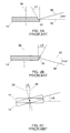
- Figs. 2A and 2B are side views of the polygon 14.
- each facet 18 should be parallel to the rotation axis 26 such that the incoming beam 12 is reflected along a plane 30 perpendicular to the rotation axis 26.
- polygons 14 are manufactured with facets, labeled 32 and 34 in Figs. 2A and 2B, respectively, at angles ⁇ 1 and ⁇ 2, respectively, to the ideal direction.
- An incoming beam which impinges an angled facet 32 or 34 is reflected along a reflection plane which is at an angle to plane 30 twice as large as the error in the facet direction.
- the reflection plane 36 is at an angle 2 ⁇ 1 to the plane 30
- the reflection plane 38 is at an angle 2 ⁇ 2 to the plane 30.
- the wobble is a rotation of the rotation axis 26 of the spinner 14 and is caused by inaccurate balancing of the polygon.
- the wobble causes a changing angular error ⁇ 3, which, in turn, causes a changing error in the reflection plane in a manner similar to that described hereinabove for Figs. 2A and 2B.
- the scanning error is typically a combination of the two types of error and there are a plurality of methods by which prior art scanning devices reduce the scanning error.
- Some prior art scanning devices include a cylindrical lens in the pre-spinner optical system 16.
- the cylindrical lens concentrates the laser beam into a line parallel to the scanning direction and focuses the concentrated beam onto the currently active facet 18.
- the cylindrical lens requires that the post-spinner optical system 20 be comprised of complicated optical elements, producing an expensive scanning device.
- the spinner 14 is comprised of an element having two flat, opposing reflective surfaces, such as a penta-prism, from which the beam reflects. Due to the opposition of the surfaces, any errors in the laser beam caused by one surface are canceled by the reflection off the second surface.
- This solution is typically utilized to reduce wobble in single faceted devices and is not easily extendible to a multi-faceted polygonal spinner.
- a beam position detector in the post-spinner optical system 20 and to include a reference beam, in addition to the scanning beam or beams, which follows a large percentage of the optical path of the scanning beams.
- the beam position detector detects the location of the reference beam, in order to continually measure the error in the location of the scanning beams.
- the measured data is provided either to acousto-optic deflectors for deflecting the reference and scanning beams to the correct location, or, as described in Israel Patent Application 94308 to the common owners of the present application, to piezo-electric crystals for shifting the location of fiber optic bundles which carry the scanning and reference beams to the correct location.
- the closed-loop control system thus produced maintains the scanning and reference beams in the desired locations.
- the beam position detector is expensive, it requires that an additional beam, the reference beam, be produced and it includes complicated optics to ensure that the two beams follow almost identical optical paths.
- an object of the present invention to provide a relatively inexpensive apparatus and method for controlling the beam location.
- a laser scanning device which includes a) a spinner for scanning a light beam having a light spot across a scanning line, b) one light spot misalignment detector located generally at a beginning of the scanned line for measuring an initial misalignment of the light spot in a cross-scanning direction and c) a beam misalignment corrector which, during scanning along the scanning line, dynamically corrects scanning misalignment in accordance with the initial misalignment.
- the beam misalignment corrector includes a) a pre-positionerwhich determines a pre-position signal which offsets the initial misalignment, b) estimation apparatus for producing, from the pre-position signal, an estimated scanning misalignment due to wobble and pyramidal error and c) a beam shifter responsive to the estimated scanning misalignment for shifting the light beam thereby to correct the scanning misalignment.
- the estimation apparatus includes a) a pyramidal error estimator for estimating a first portion of the scanning misalignment due to pyramidal error and to an extent of wobble present at the beginning of the scanning line, b) a wobble estimator for estimating a second portion of the scanning misalignment caused by the wobble and c) a summer for summing outputs of the pyramidal error estimator, the wobble estimator and the pre-positioner.
- the spinner comprises a plurality of facets and the beam misalignment corrector additionally includes apparatus for correcting in accordance with the current operative facet.
- the beam misalignment corrector additionally includes a smoother for moving the light beam from a final location of a current scan line scanned with a current facet of the spinner to a first estimated location of a next scan line, wherein the first estimated location is the value of the pre-position signal measured when the next facet was last utilized.
- the pre-positioner includes a closed loop control system controlling the beam shifter and operative to generally cancel the initial misalignment.
- the pyramidal error estimator includes a misalignment function storer for storing a misalignment function and a multiplier receiving the pre-position signal for multiplying the misalignment function by the pre-position signal.
- the wobble estimator includes a) a frequency detector which detects a spinning frequency of the spinner, b) a phase locked loop which produces a clock signal which is proportional to the spinning frequency and c) filters whose cutoff frequencies are adaptively defined by the clock signal for filtering a plurality of pre-position signals thereby to produce the second portion of the scanning misalignment.
- apparatus and method for filtering an output signal of a system in accordance with an operating frequency of the system, wherein the operating frequency changes over time.
- the apparatus includes a) a filter having at least one adaptively definable parameter for filtering the output signal, b) a detector for producing a measurement signal indicative of the operating frequency and c) a phase locked loop for producing a clock signal proportional to the measurement signal and for providing the clock signal to the filter thereby to define the at least one adaptively definable parameter.
- the method includes the steps performed by the apparatus.
- the filter is a switched capacitor filter.
- the clock signal is preferably a multiple of said measurement signal.
- the adaptively definable parameter is preferably a cutoff frequency.
- a method of laser scanning which includes the steps of a) reflecting a light beam having a light spot across a scanning line, b) measuring an initial misalignment of the light spot in a cross-scanning direction and c) during scanning, dynamically correcting scanning misalignment in accordance with the initial misalignment.
- the step of dynamically correcting includes the steps of a) determining a pre-position signal which offsets the initial misalignment, b) producing, from the pre-position signal, an estimated scanning misalignment due to wobble and pyramidal error and c) shifting the light beam in response to the estimated scanning misalignment thereby to correct the scanning misalignment.
- the step of producing includes the steps of a) estimating a first portion of the scanning misalignment due to pyramidal error and to an extent of wobble present at the beginning of the scanning line, b) estimating a second portion of the scanning misalignment caused by the wobble and c) summing the first and second portions with the pre- position signal.
- the step of reflecting is performed with a spinner and the second step of estimating includes the steps of a) detecting a spinning frequency of the spinner, b) producing, via a phase locked loop, a clock signal which is proportional to the spinning frequency and c) filtering a plurality of pre-position signals with filters whose cutoff frequencies are adaptively defined by the clock signal.
- Fig. 3A illustrates an exemplary laser scanning device 50 constructed and operative in accordance with a preferred embodiment of the present invention
- Fig. 3B illustrates the scanning surface of the system of Fig. 3A.
- the laser scanning device 50 typically can be applied to any suitable laser scanning device. It will described in the context of the scanning device shown in Fig. 3A.
- the scanning device may comprise a laser source 52 which produces a laser beam 54, a pre-spinner optical system 56 represented by a lens and operative to shape and modify the beam 54 as necessary, a spinner 58, a flat-field lens 60 and a scanning surface 62 onto which the beam 54 is scanned by each facet 64 of the spinner 58.
- a light spot location detector 68 for detecting, for each scanning line, the initial misalignment of the spot of beam 54 in the cross- scanning direction.
- a beam misalignment corrector 70 Associated with the spot detector 68 is a beam misalignment corrector 70 operative to determine, from the output of detector 68 at the beginning of the scan line, misalignment correction signals for the entire scan line and to provide the misalignment correction signals to a beam shifter 72, located between the laser 52 and the scanning surface 62.
- the beam shifter 72 can be any suitable beam shifter, such as an acousto-optic deflector operating on a laser beam or a piezoelectric actuator operating on a fiber optic waveguide. As is known in the art, the acousto-optic deflector has a much faster response time than that of the piezoelectric actuator.
- Spot detector 68 is attached to a chassis (not shown) upon which the beam shifter 72, optical system 56, spinner 58 and flat field lens 60 are located.
- the chassis can move along surface 62 in the cross-scan direction of the chassis can remain fixed and the surface 62 can move.
- the spot detector 68 is a standard bi-cell detector, such as the SPOT-2D detector from UDT Sensors, Inc. of Hawthorne, California, USA.
- the spot detector 68 measures the extent to which a spot 74 of beam 54 is not centered with respect to a line 76 to be written.
- the spot detector 68 measures the intensity of the light shining on each half, labeled A and B. If both halves have the same intensity, the beam is centered. Otherwise, the beam is off-centered in either the A direction (i.e. A has a greater intensity) or the B direction.
- the beam misalignment corrector 70 determines and implements the necessary corrections of the beam 54 over the line 76 to be scanned. The process is repeated for each line to be scanned, each of which corresponds to a different facet 64.
- Fig. 4 illustrates the elements of the beam misalignment corrector 70
- Fig. 5 illustrates the method performed by corrector 70 as part of a feedback loop defined by corrector 70, beam shifter 72 and spot detector 68 and to Figs. 6A - 6G which are useful in understanding the method of Fig. 5.
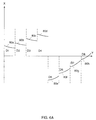
- Fig. 6A is a generalized graph of the location of the beam 54 for eight facets 64, comprised of eight misalignment curves 80.
- the horizontal axis, denoted Y (scanning direction), is the line along which the beam 54 ideally should scan, assuming that no wobble or pyramidal error exists. It is noted that eight scan lines are shown in most of Figs. 6.
- the offsets Di are the misalignments measured by the spot detector 68 at the start of each scan line and include in them offset errors due to pyramidal error and wobble.
- the beam location corrector 70 operates to correct the beam location such that curves 80 become straight lines along the Y axis. To do so, for each kth scan line and each ith facet, the corrector 70 first determines a pre-position value Gi,k which brings Di,k close to 0 and then estimates, from Gi,k, the shape of the correction curve which corrects for the relevant curve 80, where the shape of the correction curve is a function of the wobble and the pyramidal error.
- the beam location corrector 70 therefore typically comprises a pre-position determiner 84 (Fig. 4), a wobble estimator 86, a pyramidal error estimator 88 and a pre-position converter 90.
- Converter 90 can also optionally comprise a smoother 91 to provide a smooth motion from the end of one correction curve to the beginning of the next. Smoother 91 is particularly useful if the beam shifter is a relatively slow device.
- the pre-position determiner 84 performs steps 92 - 94 (Fig. 5) at the beginning of each scan line to determine the pre- position value Gi,k.
- step 94 the pre-position determiner 84 controls the beam shifter 72 so as to generally zero out the error signal e.
- step 94 is a control system loop in which the error signal e is continually measured and beam shifter 72 is continually actuated to reduce the error signal.
- the preposition determiner 84 stops operation and the value of the correction signal is typically digitized (step 100) and stored as the preposition value Gi,k.
- the preposition values for the signal of Fig. 6A are given in Fig. 6B.
- the operation of the pre-position determiner 84 should occur before the laser beam reaches the beginning of the scan line. If the pre-position determiner 84 cannot operate quickly enough, the operation can be performed over a number of scan lines which are scanned by the same facet.
- the value of Gi,k is provided, at the beginning of the kth scan line, to each of elements 86 - 90 (Fig. 4) for processing and their combined output is the estimation signal for the kth scan line error as scanned by facet i.
- pre-position converter 90 continuously provides the value of Gi,k. If only the pre-position converter 90 operated (i.e. if only the pre-position value Gi,k was used for correction), the laser beam would scan as shown in Fig.6C. As can be seen, the laser beam would begin scanning at the correct location but would become skewed over the course of the scan line. After pre-position correction, the curves are still misaligned along the scan line and they contain within them some wobble.
- curve 81e has a much larger average slope than curve 81h corresponding due to the fact that G5,k is much larger than G8,k.
- the curves can be estimated by determining both the pyramidal error and the wobble.
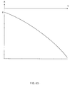
- a misalignment function describing the effect of a known pyramidal error on the location of a laser beam throughout a scan line can be calculated for the laser scanning device in which the present invention is placed through application of the physics of the optical elements.
- Software packages, such as Oslo by Sinclair Optics of Rochester, New York, USA, can be utilized to determine, from the known pyramidal error, the relationship between the scanning location, the cross-scanning error measured by the pre-position signal Gi,k and the location of the light beam on the scanning surface, for each datapoint on a scan line.
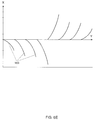
- step 104 the pyramidal error estimator 88 estimates the misalignment primarily due to pyramidal error by multiplying each of the datapoints of the misalignment function of Fig. 6D by Gi,k.
- the output of step 104 is the estimation curves 103 of Fig. 6E.
- the wobble estimator 86 is operative to estimate the frequency and amplitude of the wobble from a series of input pre- position signals Gi,k and to construct therefrom an estimated wobble signal. It is noted that the estimated wobble signal must have the same phase as the spinner 14.
- Fig. 6F illustrates one revolution of the estimated wobble signal 105 produced in step 106 (Fig. 5).
- the revolution of the wobble signal 105 occurs during one revolution of the spinner 14 and thus, only a portion 107 of signal 105 is operative for each facet i.
- step 108 the appropriate portion 107, based on the current value of i, is selected when the pre-position value Gi,k is determined.
- Portion 107 is typically comprised of a plurality of datapoints corresponding to the number of datapoints in a scan line.
- step 110 the value of the first datapoint of the selected portion 107 is determined and subtracted from each of the datapoints in portion 107.
- step 110 shifts the portion 107 towards the Y scanning axis, providing shifted signals 109.
- step 112 For each datapoint on the kth scan line corresponding to the ith facet, step 112 adds the corresponding value of shifted portion 107, of estimation curve 103 and of the current value of Gi,k to produce an estimation curve 111 (Fig. 6G) of the signal of Fig. 6A. Step 112 also multiplies the estimation curve by an appropriate factor to produce a correction signal for the beam shifter 72 for that datapoint.
- a summer 114 (Fig. 4) and an amplifier 116 performs step 112.
- pre-position converter 90 optionally includes smoother 91 to smooth the motion from one pre-position value to the next. Smoother 91 is not necessary if the reaction time of the beam shifter is fast enough.
- the output of smoother 91 is shown in Fig. 6H as sections 113.
- Smoother 91 receives, in step 120, the current pre- position value Gi,k and the pre-position value Gi+1,k-8 for the next facet as calculated the previous time the (i+1)th facet was utilized, for spinners with eight facets.
- the smoother 91 operates only at the end of the scan line 76.
- step 120 the method returns to step 92 and begins operation for the next facet and the next scan line 76.
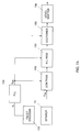
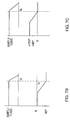
- Figs. 7A - 7C illustrate an exemplary embodiment of the wobble estimator 86 and the frequency responses of its constituent elements.
- the wobble estimator 86 typically comprises a low pass filter 130 for filtering the pre-position data Gi,k.
- the frequency response of low pass filter 130 is shown in Fig. 7B. Filter 130 passes only those frequencies less than or equal to the spinner rotation frequency Fs; however, it adds a phase delay to the output signal.
- estimator 86 additionally comprises an all pass filter 132, whose frequency response is shown in Fig. 7C, for canceling the phase delay introduced by filter 130.
- the spinner frequency Fs which is typically the cutoff frequency of filters 130 and 132, is continuously measured by a facet index detector 133 and provided to a phase locked loop (PLL) 134.
- PLL 134 provides a clock frequency Fclk to filters 130 and 132 in order to lock their cutoff frequencies to that of the spinner frequency.
- Fclk is typically a fixed multiple of Fs and filters 130 and 132 typically divide their cutoff frequency input signal Fclk by the same fixed multiple; therefore, their cutoff frequencies are Fs.
- Filters 130 and 132 are typically switched capacitor filters, such as the MF5 and MF10 filters manufactured by National Semiconductor of the USA.
- the wobble estimator 86 additionally includes a sectioner 135 for selecting the ith section of the estimated wobble signal of Fig. 6F (step 108 of Fig. 5) and a level shifter for shifting the beginning of the ith section to the horizontal axis (step 110 of Fig. 5) where the beginning is defined as the moment that the pre-position value Gi,k is determined.
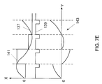
- Figs. 7D and 7E respectively illustrate an exemplary circuit for sectioner 135 and the signals labeled in Fig. 7D as 137, 139, 141 and 143.
- the circuit and signals are believed to be self-explanatory and therefore, in the interest of conciseness, will not be described herein.
- the wobble can also be measured for a system having a spinner of between one and five facets.
- a second spot detector 68 is placed at the end of a scan line, outside of the scanning area 66.
- the output of the second detector 68 is provided as input only to the wobble estimator 86 and not to the pyramidal error estimator 88.
- Fig. 8 illustrates an embodiment of the pyramidal error estimator 88, for a non necessarily linear misalignment function.
- estimator 88 comprises a storage unit 140 for storing a digitized version of the misalignment function and for receiving a Y location of the scan line 76 from a scanning clock (not shown).
- Estimator 88 also comprises a multiplying digital-to-analog converter (DAC) 142 for multiplying the current pre-position value Gi,k by the value of the misalignment function at the Y location, thereby producing the estimated signal shown in Fig. 6E.
- DAC digital-to-analog converter
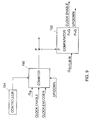
- Fig. 9 illustrates an exemplary embodiment of smoother 91 for a piezo-electric actuator type of beam shifter 72.
- the specific design of smoother 91 depends on the characteristics (e.g. bandwidth and impedance) of the beam shifter 72.
- Smoother 91 comprises a counter 150, a comparator 152 and a controller 154.
- counter 150 Upon receiving a start signal from controller 154, counter 150 accepts the current pre-position value Gi,k and changes it in accordance with control signals received from the comparator 152.
- the comparator 152 compares the next pre- position value Gi+1,k-8 to the output P of the counter 150 and, if the two values are not equal, indicates to the counter 150 to change the value of P based on the result of the comparison.
- controller 154 provides a stop signal to counter 150.
- Counter 150 increases or decreases the value of P by one unit, where the unit is a multiple of the spinner frequency Fs, provided to the counter 150 via a clock encoder, PLL or any other element synchronized with the rotation of the spinner 14.
- the value of P is continually changed until it reaches the desired value.
- the beam misalignment corrector in this embodiment additionally comprises a facet error corrector 160 whose output is directly provided to summer 114.
- Facet error corrector 160 Prior to operation of the scanner, the extent of "non-flatness" of each facet at each point along the scan line is measured and stored. Facet error corrector 160 provides an appropriate correction, as is known in the art, for the non-flatness of the the current operative facet and the current point along the scan line.
Landscapes
- Physics & Mathematics (AREA)
- General Physics & Mathematics (AREA)
- Optics & Photonics (AREA)
- Engineering & Computer Science (AREA)
- Multimedia (AREA)
- Signal Processing (AREA)
- Facsimile Scanning Arrangements (AREA)
- Mechanical Optical Scanning Systems (AREA)
- Filters That Use Time-Delay Elements (AREA)
Applications Claiming Priority (2)
| Application Number | Priority Date | Filing Date | Title |
|---|---|---|---|
| IL10518893 | 1993-03-28 | ||
| IL105188A IL105188A (en) | 1993-03-28 | 1993-03-28 | scanner |
Publications (2)
| Publication Number | Publication Date |
|---|---|
| EP0618472A2 true EP0618472A2 (de) | 1994-10-05 |
| EP0618472A3 EP0618472A3 (de) | 1995-10-11 |
Family
ID=11064662
Family Applications (1)
| Application Number | Title | Priority Date | Filing Date |
|---|---|---|---|
| EP94301979A Withdrawn EP0618472A3 (de) | 1993-03-28 | 1994-03-18 | Scanner. |
Country Status (4)
| Country | Link |
|---|---|
| US (1) | US5594556A (de) |
| EP (1) | EP0618472A3 (de) |
| JP (1) | JPH06308417A (de) |
| IL (1) | IL105188A (de) |
Cited By (13)
| Publication number | Priority date | Publication date | Assignee | Title |
|---|---|---|---|---|
| EP0747746A3 (de) * | 1995-06-05 | 1997-10-29 | Xerox Corp | Verfahren und Gerät zur Kompensation der Rasterpositionsfehler von Ausgabe-Scannern |
| WO2002023278A3 (en) * | 2000-09-15 | 2002-05-30 | Strobbe Graphics Nv | Device and method for exposing photosensitive plates for printing presses |
| EP1208352A4 (de) * | 1999-08-06 | 2002-11-27 | Metron System Inc | Profilierung eines komponentes der herabgesetzte empfindlichkeit für nicht-axialen reflektionen aufweist |
| US6822748B2 (en) | 2002-10-29 | 2004-11-23 | Metron Systems, Inc. | Calibration for 3D measurement system |
| US6825922B2 (en) | 2002-09-26 | 2004-11-30 | Metron Systems, Inc. | Determination of the angular position of a laser beam |
| US6940891B2 (en) | 2002-10-28 | 2005-09-06 | Metron Systems, Inc. | High precision optical imaging systems and related systems |
| EP1989699A4 (de) * | 2006-02-15 | 2011-03-16 | Prysm Inc | Servogesteuerte abtaststrahlanzeigesysteme mit fluoreszenzschirmen |
| US8038822B2 (en) | 2007-05-17 | 2011-10-18 | Prysm, Inc. | Multilayered screens with light-emitting stripes for scanning beam display systems |
| US8089425B2 (en) | 2006-03-03 | 2012-01-03 | Prysm, Inc. | Optical designs for scanning beam display systems using fluorescent screens |
| US8203785B2 (en) | 2006-03-31 | 2012-06-19 | Prysm, Inc. | Multilayered fluorescent screens for scanning beam display systems |
| US8232957B2 (en) | 2005-04-01 | 2012-07-31 | Prysm, Inc. | Laser displays using phosphor screens emitting visible colored light |
| US8384625B2 (en) | 2006-02-15 | 2013-02-26 | Prysm, Inc. | Servo-assisted scanning beam display systems using fluorescent screens |
| US8556430B2 (en) | 2007-06-27 | 2013-10-15 | Prysm, Inc. | Servo feedback control based on designated scanning servo beam in scanning beam display systems with light-emitting screens |
Families Citing this family (21)
| Publication number | Priority date | Publication date | Assignee | Title |
|---|---|---|---|---|
| KR19990016070A (ko) * | 1997-08-13 | 1999-03-05 | 윤종용 | 셔틀 스캐너의 수직 얼라인먼트 오차 보정 방법 |
| US6360026B1 (en) | 1998-03-10 | 2002-03-19 | Canon Kabushiki Kaisha | Method for determining a skew angle of a bitmap image and de-skewing and auto-cropping the bitmap image |
| IL127484A (en) | 1998-12-09 | 2001-06-14 | Aprion Digital Ltd | Laser container printing method and method |
| US6055057A (en) * | 1998-12-22 | 2000-04-25 | Eastman Kodak Company | Method and apparatus for accurately sensing a light beam as it passes a defined point |
| SE0102084L (sv) * | 2001-06-07 | 2002-06-11 | Saab Ab | Metod och anordning för att styra ett spegelarrangemang |
| US6635864B2 (en) * | 2001-07-13 | 2003-10-21 | Hewlett-Packard Development Company, L.P. | Measurement and correction of a scan line length error |
| US6970607B2 (en) * | 2001-09-05 | 2005-11-29 | Hewlett-Packard Development Company, L.P. | Methods for scanning and processing selected portions of an image |
| US6697096B2 (en) * | 2001-11-16 | 2004-02-24 | Applied Materials, Inc. | Laser beam pattern generator having rotating scanner compensator and method |
| US7483196B2 (en) * | 2003-09-23 | 2009-01-27 | Applied Materials, Inc. | Apparatus for multiple beam deflection and intensity stabilization |
| US7733310B2 (en) * | 2005-04-01 | 2010-06-08 | Prysm, Inc. | Display screens having optical fluorescent materials |
| US7791561B2 (en) * | 2005-04-01 | 2010-09-07 | Prysm, Inc. | Display systems having screens with optical fluorescent materials |
| US7994702B2 (en) * | 2005-04-27 | 2011-08-09 | Prysm, Inc. | Scanning beams displays based on light-emitting screens having phosphors |
| US7492450B2 (en) * | 2005-10-24 | 2009-02-17 | General Electric Company | Methods and apparatus for inspecting an object |
| US7884816B2 (en) * | 2006-02-15 | 2011-02-08 | Prysm, Inc. | Correcting pyramidal error of polygon scanner in scanning beam display systems |
| US20080068295A1 (en) * | 2006-09-19 | 2008-03-20 | Hajjar Roger A | Compensation for Spatial Variation in Displayed Image in Scanning Beam Display Systems Using Light-Emitting Screens |
| US8013506B2 (en) * | 2006-12-12 | 2011-09-06 | Prysm, Inc. | Organic compounds for adjusting phosphor chromaticity |
| US9525850B2 (en) * | 2007-03-20 | 2016-12-20 | Prysm, Inc. | Delivering and displaying advertisement or other application data to display systems |
| US7697183B2 (en) * | 2007-04-06 | 2010-04-13 | Prysm, Inc. | Post-objective scanning beam systems |
| US8169454B1 (en) | 2007-04-06 | 2012-05-01 | Prysm, Inc. | Patterning a surface using pre-objective and post-objective raster scanning systems |
| US7878657B2 (en) * | 2007-06-27 | 2011-02-01 | Prysm, Inc. | Servo feedback control based on invisible scanning servo beam in scanning beam display systems with light-emitting screens |
| US7869112B2 (en) * | 2008-07-25 | 2011-01-11 | Prysm, Inc. | Beam scanning based on two-dimensional polygon scanner for display and other applications |
Family Cites Families (11)
| Publication number | Priority date | Publication date | Assignee | Title |
|---|---|---|---|---|
| US4214157A (en) * | 1978-07-07 | 1980-07-22 | Pitney Bowes, Inc. | Apparatus and method for correcting imperfection in a polygon used for laser scanning |
| US4195316A (en) * | 1978-12-22 | 1980-03-25 | Pitney Bowes Inc. | Apparatus and method for correcting imperfection in a polygon used for laser scanning |
| US4320420A (en) * | 1980-07-03 | 1982-03-16 | Xerox Corporation | Hybrid bit clock servo |
| DE3046584C2 (de) * | 1980-12-11 | 1984-03-15 | Dr.-Ing. Rudolf Hell Gmbh, 2300 Kiel | Optisch-mechanischer Abtaster |
| US4829175A (en) * | 1985-12-05 | 1989-05-09 | Fuji Photo Film Co., Ltd. | Light beam scanning apparatus, method of correcting unevenness in scanning lines in light beam scanning apparatus, method of detecting deflection of rotational axis of light beam deflector and rotational axis deflection detecting device |
| JP2761744B2 (ja) * | 1988-12-01 | 1998-06-04 | 旭光学工業株式会社 | 走査式描画装置のポリゴンミラー分割面倒れに基づく走査ビーム補正装置 |
| EP0406844A3 (en) * | 1989-07-05 | 1992-08-19 | Canon Kabushiki Kaisha | Scanning optical apparatus |
| IL94308A0 (en) * | 1990-05-07 | 1991-03-10 | Scitex Corp Ltd | Laser scanning apparatus |
| JP2779053B2 (ja) * | 1990-09-25 | 1998-07-23 | 株式会社日立製作所 | 光走査装置 |
| US5359434A (en) * | 1991-03-26 | 1994-10-25 | Kabushiki Kaisha Toshiba | Scanning optical apparatus |
| JPH052142A (ja) * | 1991-06-24 | 1993-01-08 | Dainippon Screen Mfg Co Ltd | 光ビームの走査線偏位量検出方法および光ビーム走査装置 |
-
1993
- 1993-03-28 IL IL105188A patent/IL105188A/en not_active IP Right Cessation
-
1994
- 1994-03-18 EP EP94301979A patent/EP0618472A3/de not_active Withdrawn
- 1994-03-21 US US08/215,840 patent/US5594556A/en not_active Expired - Fee Related
- 1994-03-28 JP JP6080877A patent/JPH06308417A/ja active Pending
Cited By (22)
| Publication number | Priority date | Publication date | Assignee | Title |
|---|---|---|---|---|
| EP0747746A3 (de) * | 1995-06-05 | 1997-10-29 | Xerox Corp | Verfahren und Gerät zur Kompensation der Rasterpositionsfehler von Ausgabe-Scannern |
| US5900901A (en) * | 1995-06-05 | 1999-05-04 | Xerox Corporation | Method and apparatus for compensating for raster position errors in output scanners |
| EP1208352A4 (de) * | 1999-08-06 | 2002-11-27 | Metron System Inc | Profilierung eines komponentes der herabgesetzte empfindlichkeit für nicht-axialen reflektionen aufweist |
| US6785007B2 (en) * | 1999-08-06 | 2004-08-31 | Metron Systems, Inc. | Profiling of a component having reduced sensitivity to anomalous off-axis reflections |
| US6870631B2 (en) | 1999-08-06 | 2005-03-22 | Metron Systems, Inc. | Profiling of a component having reduced sensitivity to anomalous off-axis reflections |
| WO2002023278A3 (en) * | 2000-09-15 | 2002-05-30 | Strobbe Graphics Nv | Device and method for exposing photosensitive plates for printing presses |
| BE1013685A3 (nl) * | 2000-09-15 | 2002-06-04 | Strobbe Graphics Nv | Inrichting en werkwijze voor het belichten van fotogevoelige platen voor drukpersen. |
| US6825922B2 (en) | 2002-09-26 | 2004-11-30 | Metron Systems, Inc. | Determination of the angular position of a laser beam |
| US6940891B2 (en) | 2002-10-28 | 2005-09-06 | Metron Systems, Inc. | High precision optical imaging systems and related systems |
| US6822748B2 (en) | 2002-10-29 | 2004-11-23 | Metron Systems, Inc. | Calibration for 3D measurement system |
| US8232957B2 (en) | 2005-04-01 | 2012-07-31 | Prysm, Inc. | Laser displays using phosphor screens emitting visible colored light |
| EP1989699A4 (de) * | 2006-02-15 | 2011-03-16 | Prysm Inc | Servogesteuerte abtaststrahlanzeigesysteme mit fluoreszenzschirmen |
| US8384625B2 (en) | 2006-02-15 | 2013-02-26 | Prysm, Inc. | Servo-assisted scanning beam display systems using fluorescent screens |
| US8451195B2 (en) | 2006-02-15 | 2013-05-28 | Prysm, Inc. | Servo-assisted scanning beam display systems using fluorescent screens |
| EP2711918A3 (de) * | 2006-02-15 | 2014-08-13 | Prysm, Inc. | Servogesteuerte Abtaststrahlanzeigesysteme mit Fluoreszenzschirm |
| US8089425B2 (en) | 2006-03-03 | 2012-01-03 | Prysm, Inc. | Optical designs for scanning beam display systems using fluorescent screens |
| US8203785B2 (en) | 2006-03-31 | 2012-06-19 | Prysm, Inc. | Multilayered fluorescent screens for scanning beam display systems |
| US8233217B2 (en) | 2006-03-31 | 2012-07-31 | Prysm, Inc. | Multilayered fluorescent screens for scanning beam display systems |
| US8038822B2 (en) | 2007-05-17 | 2011-10-18 | Prysm, Inc. | Multilayered screens with light-emitting stripes for scanning beam display systems |
| US8556430B2 (en) | 2007-06-27 | 2013-10-15 | Prysm, Inc. | Servo feedback control based on designated scanning servo beam in scanning beam display systems with light-emitting screens |
| US8814364B2 (en) | 2007-06-27 | 2014-08-26 | Prysm, Inc. | Servo feedback control based on designated scanning servo beam in scanning beam display systems with light-emitting screens |
| US9467668B2 (en) | 2007-06-27 | 2016-10-11 | Prysm, Inc. | Feedback control of display systems with light-emitting screens having excitation light source and phosphor layer |
Also Published As
| Publication number | Publication date |
|---|---|
| EP0618472A3 (de) | 1995-10-11 |
| IL105188A (en) | 1998-02-08 |
| JPH06308417A (ja) | 1994-11-04 |
| US5594556A (en) | 1997-01-14 |
Similar Documents
| Publication | Publication Date | Title |
|---|---|---|
| US5594556A (en) | Scanner having a misalignment detector | |
| EP0660578B1 (de) | Schwankungskorrekturverfahren und -vorrichtung unter Verwendung von einem in der Richtung steuerbaren Strahl-/Rasterausgabeabtaster mit Polygon und einer sphärischen Optik | |
| US6873421B2 (en) | Method and apparatus for measuring the three-dimensional shape of an object using a moire equipment | |
| US5245181A (en) | Method and apparatus of detecting deviation of scanning line of light beam | |
| US4433894A (en) | Method and apparatus for generating optical scans | |
| JP2005062372A (ja) | 位置検出装置、光学装置、撮像システム、位置検出方法およびプログラム | |
| US6608705B1 (en) | Image reading device and focus adjustment method thereof | |
| US5615038A (en) | Scanning optical device with aberration compensation feature | |
| US6919979B2 (en) | Optical scanning apparatus | |
| JPS60221720A (ja) | 光ビ−ム走査装置 | |
| JP2731565B2 (ja) | 測距センサー | |
| US5869945A (en) | Infrared scanner | |
| EP0869384A1 (de) | Winkeldetektor und detektionsverfahren mit spiegel | |
| JP4007854B2 (ja) | サンプリングクロック発生装置 | |
| JPH05228672A (ja) | 自動アライメント調整装置 | |
| US7330312B2 (en) | Image blur compensation device | |
| JPH04101114A (ja) | 画像走査装置 | |
| EP0390969A2 (de) | Positionierungssystem | |
| US10649204B2 (en) | Device and method for deflecting a light beam in order to scan a solid angle range | |
| CA2159367A1 (en) | Facet inaccuracy compensation unit | |
| JP2808959B2 (ja) | 灯台式センサでの計測による仮想点位置推定方法 | |
| JP4819991B2 (ja) | 走査型光学顕微鏡の倍率調整方法及びその装置 | |
| JP3496171B2 (ja) | 光ビームを回転多面鏡によって偏向して記録体上を走査する装置の周期的ムラ補正パターンの決定方法及び装置 | |
| US20030058333A1 (en) | Strip neutral density filter for correcting intensity non-uniformity in a raster output scanning system | |
| JPH04313714A (ja) | 試料テ−ブルの傾斜補正装置 |
Legal Events
| Date | Code | Title | Description |
|---|---|---|---|
| PUAI | Public reference made under article 153(3) epc to a published international application that has entered the european phase |
Free format text: ORIGINAL CODE: 0009012 |
|
| AK | Designated contracting states |
Kind code of ref document: A2 Designated state(s): DE FR GB IT |
|
| PUAL | Search report despatched |
Free format text: ORIGINAL CODE: 0009013 |
|
| AK | Designated contracting states |
Kind code of ref document: A3 Designated state(s): DE FR GB IT |
|
| STAA | Information on the status of an ep patent application or granted ep patent |
Free format text: STATUS: THE APPLICATION IS DEEMED TO BE WITHDRAWN |
|
| 18D | Application deemed to be withdrawn |
Effective date: 19960412 |