EP0618659A1 - Kommutatormotor-Getriebe-Antriebseinheit, insbesondere Kraftfahrzeug-Fensterheberantrieb - Google Patents
Kommutatormotor-Getriebe-Antriebseinheit, insbesondere Kraftfahrzeug-Fensterheberantrieb Download PDFInfo
- Publication number
- EP0618659A1 EP0618659A1 EP93105355A EP93105355A EP0618659A1 EP 0618659 A1 EP0618659 A1 EP 0618659A1 EP 93105355 A EP93105355 A EP 93105355A EP 93105355 A EP93105355 A EP 93105355A EP 0618659 A1 EP0618659 A1 EP 0618659A1
- Authority
- EP
- European Patent Office
- Prior art keywords
- housing
- motor
- drive unit
- circuit board
- electronics
- Prior art date
- Legal status (The legal status is an assumption and is not a legal conclusion. Google has not performed a legal analysis and makes no representation as to the accuracy of the status listed.)
- Granted
Links
Images


Classifications
-
- H—ELECTRICITY
- H02—GENERATION; CONVERSION OR DISTRIBUTION OF ELECTRIC POWER
- H02K—DYNAMO-ELECTRIC MACHINES
- H02K7/00—Arrangements for handling mechanical energy structurally associated with dynamo-electric machines, e.g. structural association with mechanical driving motors or auxiliary dynamo-electric machines
- H02K7/10—Structural association with clutches, brakes, gears, pulleys or mechanical starters
- H02K7/116—Structural association with clutches, brakes, gears, pulleys or mechanical starters with gears
- H02K7/1163—Structural association with clutches, brakes, gears, pulleys or mechanical starters with gears where at least two gears have non-parallel axes without having orbital motion
- H02K7/1166—Structural association with clutches, brakes, gears, pulleys or mechanical starters with gears where at least two gears have non-parallel axes without having orbital motion comprising worm and worm-wheel
-
- H—ELECTRICITY
- H02—GENERATION; CONVERSION OR DISTRIBUTION OF ELECTRIC POWER
- H02K—DYNAMO-ELECTRIC MACHINES
- H02K11/00—Structural association of dynamo-electric machines with electric components or with devices for shielding, monitoring or protection
- H02K11/30—Structural association with control circuits or drive circuits
- H02K11/38—Control circuits or drive circuits associated with geared commutator motors of the worm-and-wheel type
-
- H—ELECTRICITY
- H02—GENERATION; CONVERSION OR DISTRIBUTION OF ELECTRIC POWER
- H02K—DYNAMO-ELECTRIC MACHINES
- H02K23/00—DC commutator motors or generators having mechanical commutator; Universal AC/DC commutator motors
- H02K23/66—Structural association with auxiliary electric devices influencing the characteristic of, or controlling, the machine, e.g. with impedances or switches
-
- H—ELECTRICITY
- H02—GENERATION; CONVERSION OR DISTRIBUTION OF ELECTRIC POWER
- H02K—DYNAMO-ELECTRIC MACHINES
- H02K5/00—Casings; Enclosures; Supports
- H02K5/04—Casings or enclosures characterised by the shape, form or construction thereof
- H02K5/22—Auxiliary parts of casings not covered by groups H02K5/06-H02K5/20, e.g. shaped to form connection boxes or terminal boxes
- H02K5/225—Terminal boxes or connection arrangements
-
- H—ELECTRICITY
- H02—GENERATION; CONVERSION OR DISTRIBUTION OF ELECTRIC POWER
- H02K—DYNAMO-ELECTRIC MACHINES
- H02K2211/00—Specific aspects not provided for in the other groups of this subclass relating to measuring or protective devices or electric components
- H02K2211/03—Machines characterised by circuit boards, e.g. pcb
-
- H—ELECTRICITY
- H02—GENERATION; CONVERSION OR DISTRIBUTION OF ELECTRIC POWER
- H02K—DYNAMO-ELECTRIC MACHINES
- H02K5/00—Casings; Enclosures; Supports
- H02K5/04—Casings or enclosures characterised by the shape, form or construction thereof
- H02K5/14—Means for supporting or protecting brushes or brush holders
- H02K5/143—Means for supporting or protecting brushes or brush holders for cooperation with commutators
- H02K5/148—Slidably supported brushes
Definitions
- the invention relates to a commutator motor gear drive unit, in particular a motor vehicle window regulator drive, according to the preamble of claim 1; such a drive unit is known from EP-A1-0 474 904.
- the printed circuit board integrated with the brush plate is inserted perpendicular to the plane defined by the housing flanges in an extension of the cup-shaped gear housing, which can be replaced by a cover which can be mounted perpendicular to the plane defined by the housing flanges is tightly sealed on the outside;
- a more compact construction of a drive unit provided with an externally protected electronics, in particular for a motor vehicle window regulator drive, is to be created with simplified manufacture and assembly; this object is achieved in a commutator motor gear drive unit of the type mentioned at the outset by the teaching of claim 1; advantageous embodiments of the invention are the subject of the dependent claims.
- a commutator motor gear drive unit creates an axially assembly assembly which is advantageous in terms of production technology Component unit, with its printed circuit board accommodated in the plane of the housing flanges and simultaneously mountable in a protective cover when assembling the motor housing on the one hand and the gear housing on the other hand, is a compact drive unit that can be assembled and assembled with little effort.
- an electronics housing with a first electronics housing part which essentially corresponds to the end contour of the housing flange of the commutator motor and a radially adjoining, shell-shaped underneath the motor housing Commutator motor extending and on its open, the transmission flange facing axial loading side for the printed circuit board through the correspondingly only radially expanded housing flange of the transmission housing during its assembly on the motor housing simultaneously closing second electronics housing part;
- a plug receptacle is expediently provided with a plug which leads to the outside in a sealed manner and can be connected to conductor guides of the printed circuit board.
- the two front-side contact edges of the electronics housing against which on the one hand the end face of the housing flange of the motor housing and on the other hand the end face of the gear flange of the gear housing rests, in each case a sealing edge, in particular sprayed on, applied.
- motor housing 1 shows a motor vehicle window lifter drive with a plastic motor housing 1 and a plastic gear housing 2 flanged to it.
- motor housing 1 has a housing flange 1.1
- gear housing 2 has a housing flange 2.1, which is radial projecting flange edges are braced against each other in a manner not shown here by axial screwing.
- An electronics housing 3 is clamped between the housing flanges 1.1., 1.2, which for the motor housing 1 - as can be seen in particular from FIG. 3; 4 - consists of a first, essentially only one bearing edge, first electronics housing part 3.1 and one, essentially to accommodate a printed circuit board 4 equipped with electronic or electrical components or an electronics housing part 3.2 having a plug receptacle.
- the circuit board 4 is pre-assembled in the electronics housing 3, brushes 4.5; 4.6 being received in the area of the first electronics housing part 3.1 by the circuit board designed there as a brush plate, which are used to allocate current to a commutator 7.1 which is on the rotor shaft 7 of the commutator motor is arranged; among others A rotor shaft supported in a spherical bearing 7.3 projects as a worm shaft into the gear housing 2.
- the circuit board 4 is used essentially for receiving an insertable chip board 4.4, a relay 4.3; and of connector parts 4.1; 4.2, which lead sealed to the outside by a connector seal 9 through a connector receptacle 3.21 in the second electronics housing part 3.2 to connect a customer connector.
- a Hall sensor 8 is arranged, which is assigned to a magnet wheel 7.2 held on the rotor shaft 3 and serves as a speed or direction sensor.
- 7.2 is assigned and serves as a speed or direction sensor.
- a sealing edge 5 or 6 is sprayed onto the two end faces of the electronics housing 3 clamped between the motor housing 1 and the gear housing 2 on the contact side such that, on the one hand, the housing flange 1.1 of the motor housing 1 relative to the one contact edge of the first electronics housing part 3.1 and, on the other hand, the one after radially below as a cover for the open circuit board loading side of the electronics housing 3, the enlarged gear flange 2.1 of the gear housing 2 against the seal 6 of the other front-side abutment edge of the first electronics housing 3.1 and also of the second electronics housing part 3.2 is sealingly seated and thus advantageously in the electronics housing 3 preassembled circuit board 4 are covered with an integrated brush plate that is protected against moisture.
- the electronics housing 3 is supported via contact webs 3.3; 3.4; 3.5 at such a distance from the housing flange 2.1 of the gear housing 2 that there is a sufficient distance from the rear side of the printed circuit board 4.
- the covering design of the housing flange 2.1 of the gear housing 2 and the moisture-proof bearing receptacle of the spherical bearing 7.3 ensure that also no moisture can get into the electronics housing 3 from the gear housing 2.
- axially protruding guide webs 2.11-2.14 are integrally formed on the housing flange 2.1 of the gear housing, which plunge into corresponding step-shaped guide receptacles of the printed circuit board 4; in the same way, the printed circuit board 4 has guide webs 4.8; 4.9 in the opposite direction, which are immersed in corresponding guide receptacles 2.15; 2.16 of the housing flange 2.1 of the gear housing.
- a guide or cover sleeve 4.7 formed on the printed circuit board 4 covers the brush and commutator area of the commutator motor and at the same time serves to align or fix the printed circuit board 4 relative to the motor housing 1.1 of the commutator motor.
- the motor housing 1 is expediently equipped with all the rotor components with only one handling direction, then the electronics housing 3 with preassembled printed circuit board 4 and finally the gear housing 2 are placed on, and the compact component unit is clamped together by the motor housing 1 and the gear housing 2 being clamped together summarized and covered the circuit board 4 with the electronics tightly to the outside.
Landscapes
- Engineering & Computer Science (AREA)
- Power Engineering (AREA)
- Connection Of Motors, Electrical Generators, Mechanical Devices, And The Like (AREA)
- Motor Or Generator Frames (AREA)
Abstract
Description
- Die Erfindung bezieht auf eine Kommutatormotor-Getriebe-Antriebseinheit, insbesondere Kraftfahrzeug-Fensterheberantrieb, gemäß Oberbegriff des Anspruchs 1; eine derartige Antriebseinheit ist durch die EP-A1-0 474 904 bekannt.
- Bei der durch die EP-A1-0 474 904 bekannten Antriebseinheit ist die mit der Bürstenplatte integrierte Leiterplatte senkrecht zu der durch die Gehäuseflansche definierte Ebene in einer Erweiterung des topfförmigen Getriebegehäuses eingelegt, das durch einen senkrecht zu der durch die Gehäuseflansche definierten Ebene montierbaren Deckel nach außen dicht verschlossen wird; der auf der in das Getriebegehäuse verlängerten Rotorwelle des Kommutatormotors angeordnete Kommutator reicht axial über die Gehäuseflanschebene hinaus in das Getriebegehäuse hinein und wird dort von Bürsten beschliffen, die auf einem in das Getriebegehäuse ragenden Ansatz der Leiterplatte montiert sind.
- Gemäß Aufgabe vorliegender Erfindung soll bei vereinfachter Fertigung und Montage eine kompaktere Bauweise einer mit einer nach außen geschützen Elektronik versehenen Antriebseinheit, insbesondere für einen Kraftfahrzeug-Fensterheberantrieb, geschaffen werden; die Lösung dieser Aufgabe gelingt bei einer Kommutatormotor-Getriebe-Antriebseinheit der eingangs genannten Art durch die Lehre des Anspruchs 1; vorteilhafte Ausgestaltungen der Erfindung sind jeweils Gegenstand der Unteransprüche.
- Die erfindungsgemäße Konstruktion einer Kommutatormotor-Getriebe-Antriebseinheit schafft eine in fertigungstechnisch vorteilhafter axialer Aufbaumontage fügbare Bauteileinheit, die mit ihrer in der Ebene der Gehäuseflansche untergebrachte und gleichzeitig beim Zusammenbau von Motorgehäuse einerseits und Getriebegehäuse andererseits im geschützer Abdeckung montierbare Leiterplatte eine kompakte und mit geringem Aufwand fertigbare und montierbare Antriebseinheit.
- In vorteilhafter Weise ist zur geschützen Unterbringung von auf der Leiterplatte gehaltenen und kontaktierenden elektrischen bzw. elektronischen Bauelementen ein Elektronik-Gehäuse mit einem im wesentlichen der stirnseitigen Kontur des Gehäuseflansches des Kommutatormotors entsprechenden ersten Elektronik-Gehäuseteil und einem radial anschließenden, sich schalenförmig unterhalb des Motorgehäuses des Kommutatormotors erstreckenden und an seiner offenen, den Getriebeflansch zugewandten axialen Beschickungsseite für die Leiterplatte durch den entsprechend lediglich radial erweiterten Gehäuseflansch des Getriebegehäuses bei dessen Montage an das Motorgehäuse gleichzeitig verschließenden zweiten Elektronik-Gehäuseteil; im Schalenboden des zweiten Gehäuseteils ist dabei zweckmäßigerweise eine Steckeraufnahme mit einem abgedichtet nach außen führenden, mit Leiterführungen der Leiterplatte verbindbaren Stecker vorgesehen.
- Zur Vereinfachung des Zusammenbaus der erfindungsgemäßen Kommutatormotor-Getriebe-Antriebseinheit ist weiterhin vorgesehen, die Leiterplatte entweder in dem zweiten Elektronik-Gehäuseteil bzw. in dem gegenüberliegenden Gehäuseflansch des Getriebegehäuses vorzumontieren, derart daß die Leiterplatte beim Zusammenbau von Motorgehäuse einerseits und Getriebegehäuse andererseits entweder mit dem zwischenliegenden Elektronikgehäuse oder mit dem Getriebegehäuse ohne gesonderte Handhabungbewegung für eine entsprechende Bauteil-Zuführung montierbar ist.
- Um beim Zusammenbau von Motorgehäuse einerseits und Getriebegehäuse andererseits eine quetschfreie dichte gegenseitige Anlage der Gehäusesflansche mit gleichzeitigem Zwischeneinschluß des Elektronikgehäuses erreichen zu können, ist nach einer Ausgestaltung der Erfindung auf die beiden stirnseitigen Anlageränder des Elektronikgehäuses, gegen die einerseits die Stirnseite des Gehäuseflansches des Motorgehäuses und andererseits die Stirnseite des Getriebeflansches des Getriebegehäuses anliegt, jeweils ein, insbesondere aufgespritzter, Dichtrand aufgebracht.
- Die Erfindung sowie weitere vorteilhafte Ausgestaltungen der Erfindung werden im folgenden anhand eines schematisch dargestelllten Ausführungsbeispiels in der Zeichnung näher erläutert; darin zeigen
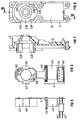
- FIG 1
- in einem axialen Längsschnitt einen Teilausschnitt aus einem Kraftfahrzeug-Fensterheberantrieb im Bereich der zusammenmontierbaren Gehäuseflansche vom Motorgehäuse einerseits und Getriebegehäuse andererseits,
- FIG 2
- eine axiale stirnseitige Draufsicht auf den Gehäuseflansch des Motorgehäuses,
- FIG 3
- in einem axialen Längsschnitt das zwischen den Gehäuseflansche fixierbare Elektronikgehäuse, gemäß Schnittverlaut III-III in FIG 4,
- FIG 4
- die axiale getriebegehäuseseitige stirnseitige Draufsicht auf das Elektronikgehäuse gemäß FIG 3,
- FIG 5
- in einer axialen Seiteneinsicht die bestückte Leiterplatte,
- FIG 6
- die motorgehäuseseitige axiale stirnseitige Draufsicht auf die Leiterplatte gemäß FIG 5,
- FIG 7
- in einem axialen Längsschnitt einen Teilausschnitt aus dem Getriebegehäuse im Bereich des Gehäuseflansches gemäß Schnittverlauf VII-VII in FIG 8,
- FIG 8
- die motorgehäuseseitige axiale stirnseitige Draufsicht auf das Getriebegehäuse gemäß FIG 7.
- FIG 1 zeigt einen Kraftfahrzeug-Fensterheberantrieb mit einem Kunststoff-Motorgehäuse 1 und einem daran angeflanschten Kunststoff-Getriebegehäuse 2. Zur gegenseitigen Montage von Motorgehäuse 1 und Getriebegehäuse 2 weist das Motorgehäuse 1 einen Gehäuseflansch 1.1 und das Getriebegehäuse 2 einen Gehäuseflansch 2.1 auf, die mit radial überstehenden Gehäuseflanschrändern in hier nicht näher dargestellter Weise durch axiale Verschraubung gegeneinander verspannt sind. Zwischen den Gehäuseflanschen 1.1.;1.2 ist dabei ein Elektronikgehäuse 3 eingeklemmt, das für das Motorgehäuse 1 - wie insbes. aus FIG 3;4 ersichtlich - aus einem ersten, im wesentlichen nur einen Anlagerand aufweisenden ersten Elektronik-Gehäuseteil 3.1 und einem, im wesentlichen zur Aufnahme einer mit elektronischen bzw. elektrischen Bauteilen bestückten Leiterplatte 4 bzw. eine Steckeraufnahme aufweisenden Elektronik-Gehäuseteil 3.2 besteht.
- Die Leiterplatte 4 ist in das Elektronikgehäuse 3 vormontierbar eingelegt, wobei im Bereich des ersten Elektronik-Gehäuseteils 3.1 von der dort als Bürstenplatte ausgebildeten Leiterplatte Bürsten 4.5;4.6 aufgenommen werden, die der Stromzuteilung zu einem Kommutator 7.1 dienen, der auf der Rotorwelle 7 des Kommutatormotors angeordnet ist; die u.a. in einem Kalottenlager 7.3 gelagerte Rotorwelle ragt als Schneckenwelle in das Getriebegehäuse 2.
- In ihrem radial unteren Teil dient die Leiterplatte 4 im wesentlichen zur Aufnahme einer einsteckbaren Chipplatte 4.4, eines Relais 4.3; sowie von Steckerteilen 4.1;4.2, die abgedichtet durch eine Steckerdichtung 9 durch eine Steckeraufnahme 3.21 im zweiten Elektronik-Gehäuseteil 3.2 nach außen zum Anschluß eines Kundensteckers führen. Im oberen Teil der Leiterplatte 4 ist ein Hall-Sensor 8 angeordnet, der einem auf der Rotorwelle 3 gehaltenen Polrad 7.2 zugeordnet ist und als Drehzahl- bzw. Drehrichtungsgeber dient.
- 7.2 zugeordnet ist und als Drehzahl- bzw. Drehrichtungsgeber dient.
- Sämtliche von der Leiterplatte 4 aufgenommenen und mit dieser bzw. untereinander zu kontaktierenden Bauteile, insbesondere die Steckerteile 4.1;4.2, das Relais 4.3, die Chipplatte 4.4, der Hall-Sensor 8 sowie zu den Bürsten führende Bürstenlitzen 4.51 sind in vorteilhafter Weise von der motorgehäuseseitigen Vorderseite der Leiterplatte 4 axial zuführbar montiert und durch Tauchlöten vor durch die Leiterplatte 4 zu deren Rückseite durchgesteckten Kontaktstiften kontaktierbar.
- Auf die beiden zwischen dem Motorgehäuse 1 und dem Getriebegehäuse 2 anlagerandseitig eingeklemmten Stirnseiten des Elektronikgehäuses 3 ist je ein Dichtrand 5 bzw. 6 derart aufgespritzt, daß einerseits der Gehäuseflansch 1.1 des Motorgehäuses 1 gegenüber dem einen Anlagerand des ersten Elektronik-Gehäuseteils 3.1 und andererseits der nach radial unten als Abdeckung für die offene Leiterplatten-Beschickungseite des Elektronikgehäuses 3 erweiterte Getriebeflansch 2.1 des Getriebegehäuses 2 gegen die Dichtung 6 des anderen stirnseitigen Anlagerandes des ersten Elektronikgehäuses 3.1 als auch des zweiten Elektronik-Gehäuseteils 3.2 dichtend anliegt und derart in vorteilhafter Weise die in Elektronikgehäuse 3 vormontierbare Leiterplatte 4 mit ingegrierter Bürstenplatte nach außen feuchtigkeitsdicht geschützt abgedeckt sind.
- Das Elektronikgehäuse 3 stützt sich über Anlagestege 3.3;3.4;3.5 in solchem Abstand gegenüber dem Gehäuseflansch 2.1 des Getriebegehäuse 2 ab, daß ein hinreichender Abstand zur Rückseite der Leiterplatte 4 gegeben ist. Durch die abdeckende Ausbildung des Gehäuseflansches 2.1 des Getriebegehäuses 2 und die feuchtigkeitsdichte Lageraufnahme des Kalottenlagers 7.3 ist gewährleistet, daß auch keine Feuchtigkeit vom Getriebegehäuse 2 her in das Elektronikgehäuse 3 gelangen kann.
- Zur Vereinfachung einer axialen Aufbaumontage sind in vorteilhafter Weise an den Gehäuseflansch 2.1 des Getriebegehäuses axial vorstehende Führungsstege 2.11-2.14 angeformt, die in korrespondierende stufenförmige Führungsaufnahmen der Leiterplatte 4 eintauchen; in gleicher Weise weist die Leiterplatte 4 in Gegenrichtung Führungsstege 4.8;4.9 auf, die in korrespondierende Führungsaufnahmen 2.15;2.16 des Gehäuseflansches 2.1 des Getriebegehäuses eintauchen. Eine an die Leiterplatte 4 angeformte Führungs- bzw. Abdeckhülse 4.7 deckt einerseits den Bürsten- und Kommutatorbereich des Kommutatormotors ab und dient gleichzeitig der Ausrichtung bzw. Fixierung der Leiterplatte 4 relativ zum Motorgehäuse 1.1 des Kommutatormotors.
- Bei der erfindungsgemäß vorteilhaften axialen Aufbaumontage sämtlicher wesentlicher Bauteile werden zweckmäßigerweise mit nur einer Handhabungsrichtung das Motorgehäuse 1 mit sämtlichen Rotorbauteilen bestückt, dann das Elektronikgehäuse 3 mit vormontierter Leiterplatte 4 und schließlich das Getriebegehäuse 2 aufgelegt und durch gegenseitiges Verspannen von Motorgehäuse 1 und Getriebegehäuse 2 die kompakte Bauteileinheit zusammengefaßt und dabei die Leiterplatte 4 mit der Elektronik nach außen dicht abgedeckt.
Claims (10)
- Kommutatormotor-Getriebe-Antriebseinheit, insbesondere Kraftfahrzeug-Fensterheberantrieb, mit stirnseitig aneinanderliegenden Gehäuseflanschen (1.1;2.1) eines Motorgehäuses (1) einerseits und eines Getriebegehäuses (2) andererseits und mit einem eine Leiterplatte (4) mit integrierter Bürstenplatte für den Kommutatormotor zumindest teilweise abdeckenden Elektronik-Gehäuse (3), dadurch gekennzeichnet, daß sich die Leiterplatte (4) im wesentlichen parallel zu den Gehäuseflanschen (1.1;2.1) zwischen diesen erstreckt und auf ihrer einen axialen Stirnseite durch das Motorgehäuse (1) bzw. das Elektronikgehäuse (3) und auf ihrer anderen axialen Stirnseite durch das Getriebegehäuse (2) nach außen dicht abgedeckt ist.
- Antriebseinheit nach Anspruch 1, gekennzeichnet durch ein Elektronik-Gehäuse (3) mit einem im wesentlichen der stirnseitigen Kontur des Gehäuseflansches (1.1) des Kommutatormotors entsprechenden ersten Elektronik-Gehäuseteil (3.1) und einem radial anschließenden, sich schalenförmig unterhalb des Motorgehäuses (1) des Kommutatormotors erstreckenden und an seiner offenen axialen Beschickungseite durch den entsprechend radial erweiterten Gehäuseflansch (2.1) des Getriebegehäuses (2) verschließenden zweiten Elektronik-Gehäuseteil (3.2).
- Antriebeinheit nach Anspruch 2, gekennzeichnet durch eine Steckeraufnahme (3.21) mit einem abgedichtet nach außen führenden, mit Leiterführungen der Leiterplatte (4) verbundenen Steckern (4.1;4.2) im Schalenboden des zweiten Elektronik-Gehäuseteils (3.2).
- Antriebseinheit nach einem der Ansprüche 1-3, gekennzeichnet durch eine in dem Elektronikgehäuse (3) bzw. in dem gegenüberliegenden Gehäuseflansch (2.1) des Getriebegehäuses (2) vormontierbare bzw. fixierbare, insbesondere bereits mit sich in den schalenförmigen zweiten Elektronik-Gehäuseteil (3.2) erstreckenden Elektronikbausteinen bzw. mit Bürsten bzw. mit Kontaktelementen und deren gegenseitigen Verbindungen bestückte, Leiterplatte (4).
- Antriebseinheit nach Anspruch 4, gekennzeichnet durch eine von der, vorzugsweise kommutatormotorseitigen, Vorderseite axial bestückbare und durch Tauchlöten von durch deren Rückseite durchgesteckten Kontaktstiften kontaktierbare Leiterplatte (4).
- Antriebseinheit nach einem der Ansprüche 1-5, gekennzeichnet durch anlagerandseitig auf das Elektronikgehäuse (3) aufgebrachte, insbesondere aufgespritzte, Dichtränder (5;6), gegen die der Gehäuseflansch (1.1) des Motorgehäuses (1) bzw. der Gehäuseflansch (2.1) des Getriebegehäuses (2) anliegen.
- Antriebseinheit nach einem der Ansprüche 1-6, gekennzeichnet durch eine an die Leiterplatte (4) angeformte, das Motorgehäuse (1) axial untergreifende, zumindest den Kommutatorbereich des Kommutatormotors axial übergreifende Führungs- und/oder Abdeckhülse (4.7).
- Antriebseinheit nach einem der Ansprüche 1-7, gekennzeichnet durch an den Gehäuseflansch (2.1) des Getriebegehäuses (2) angeformte axial vorstehende Führungsstege (2.11;2.12;2.13;2.14), die in korrespondierende Führungsaufnahmen der Leiterplatte (4) axial eintauchen.
- Antriebseinheit nach einem der Ansprüche 1-8, gekennzeichnet durch an die Leiterplatte (4) angeformte axial vorstehende Führungsstege (4.8;4.9), die in korrespondierende Führungsaufnahmen (2.15;2.16) des Gehäuseflansches (2.1) des Getriebegehäuses (2) Führung axial eintauchen.
- Antriebseinheit nach einem der Ansprüche 1-9, dadurch gekennzeichnet, daß zumindest das Motorgehäuse(1), das Elektronikgehäuse (3), die Leiterplatte (4) sowie das Getriebegehäuse (2) Teile einer in axialer Aufbaumontage fügbaren Bauteileinheit sind.
Priority Applications (4)
| Application Number | Priority Date | Filing Date | Title |
|---|---|---|---|
| EP93105355A EP0618659B2 (de) | 1993-03-31 | 1993-03-31 | Kommutatormotor-Getriebe-Antriebseinheit, insbesondere Kraftfahrzeug-Fensterheberantrieb |
| DE59300052T DE59300052D1 (de) | 1993-03-31 | 1993-03-31 | Kommutatormotor-Getriebe-Antriebseinheit, insbesondere Kraftfahrzeug-Fensterheberantrieb. |
| ES93105355T ES2066624T5 (es) | 1993-03-31 | 1993-03-31 | Unidad de accionamiento con engranaje y motor de conmutador, en especial accionamiento para elevalunas de vehiculos de motor. |
| US08/218,545 US5528093A (en) | 1993-03-31 | 1994-03-28 | Commutator-motor gear/drive unit, in particular a window-lift drive for a motor vehicle |
Applications Claiming Priority (1)
| Application Number | Priority Date | Filing Date | Title |
|---|---|---|---|
| EP93105355A EP0618659B2 (de) | 1993-03-31 | 1993-03-31 | Kommutatormotor-Getriebe-Antriebseinheit, insbesondere Kraftfahrzeug-Fensterheberantrieb |
Publications (3)
| Publication Number | Publication Date |
|---|---|
| EP0618659A1 true EP0618659A1 (de) | 1994-10-05 |
| EP0618659B1 EP0618659B1 (de) | 1994-12-28 |
| EP0618659B2 EP0618659B2 (de) | 2001-07-04 |
Family
ID=8212770
Family Applications (1)
| Application Number | Title | Priority Date | Filing Date |
|---|---|---|---|
| EP93105355A Expired - Lifetime EP0618659B2 (de) | 1993-03-31 | 1993-03-31 | Kommutatormotor-Getriebe-Antriebseinheit, insbesondere Kraftfahrzeug-Fensterheberantrieb |
Country Status (4)
| Country | Link |
|---|---|
| US (1) | US5528093A (de) |
| EP (1) | EP0618659B2 (de) |
| DE (1) | DE59300052D1 (de) |
| ES (1) | ES2066624T5 (de) |
Cited By (12)
| Publication number | Priority date | Publication date | Assignee | Title |
|---|---|---|---|---|
| EP0823768A1 (de) * | 1996-08-05 | 1998-02-11 | Mitsuba Corporation Co., Ltd. | Struktur zum Versorgen eines elektrischen Motors |
| EP0865148A1 (de) * | 1997-03-12 | 1998-09-16 | Robert Bosch Gmbh | Kommutatormotor mit Motorbetriebssensor |
| EP1564867A4 (de) * | 2002-11-19 | 2007-03-21 | Asmo Co Ltd | Motor und verfahren zur herstellung eines motors |
| FR2892572A1 (fr) * | 2005-10-20 | 2007-04-27 | Bosch Gmbh Robert | Machine electrique et procede de montage |
| US7254880B2 (en) | 2000-04-22 | 2007-08-14 | Brose Fahrzeuqteile Gmbh & Co. Kg, Coburg | Electromechanical drive device and method for manufacture thereof |
| US7663273B2 (en) | 2004-11-22 | 2010-02-16 | Hitachi, Ltd. | Motor control apparatus, power steering apparatus and brake control apparatus |
| WO2011064029A1 (de) * | 2009-11-25 | 2011-06-03 | Robert Bosch Gmbh | Elektrische anschlusseinrichtung und scheibenwischerantrieb mit einer elektrischen anschlusseinrichtung |
| WO2012076268A3 (de) * | 2010-12-09 | 2013-07-04 | Robert Bosch Gmbh | Elektromotorantrieb |
| DE102012221603A1 (de) * | 2012-11-27 | 2014-06-12 | Robert Bosch Gmbh | Stellantriebsanordnung |
| WO2018091493A1 (de) * | 2016-11-16 | 2018-05-24 | Robert Bosch Gmbh | Elektrische maschine mit einem bürstenhalter-bauteil und einem steckermodul |
| WO2020157179A1 (de) * | 2019-02-01 | 2020-08-06 | Nidec Motors & Actuators (Germany) Gmbh | Verstellantrieb aufweisend eine bürstenkartenanordnung mit integrierter leiterplatte |
| WO2020249735A1 (de) * | 2019-06-14 | 2020-12-17 | Dewertokin Gmbh | Entstörter linearantrieb |
Families Citing this family (64)
| Publication number | Priority date | Publication date | Assignee | Title |
|---|---|---|---|---|
| DE59300165D1 (de) * | 1993-09-08 | 1995-06-08 | Siemens Ag | Motor-Pumpen-Aggregat, insbesondere Kraftfahrzeug-Antiblockier-Bremsvorrichtung. |
| DE4419215A1 (de) * | 1994-06-01 | 1995-12-07 | Bosch Gmbh Robert | Baueinheit für Regler und Bürstenhalter und dessen Herstellverfahren |
| US6051899A (en) * | 1996-06-15 | 2000-04-18 | Itt Manufacturing Enterprises, Inc. | Drive mechanism |
| DE19644169A1 (de) * | 1996-10-24 | 1998-04-30 | Mannesmann Vdo Ag | Lastverstelleinrichtung |
| DE19710015A1 (de) * | 1997-03-12 | 1998-09-17 | Bosch Gmbh Robert | Motor mit Drehzahlabgriff über einen Hall-Sensor |
| DE19746518A1 (de) * | 1997-10-22 | 1999-04-29 | Bosch Gmbh Robert | Einschubmodul für einen elektromotorischen Fensterheber |
| US6317332B1 (en) | 1998-02-05 | 2001-11-13 | Robert Bosch Gmbh | Electronic module for an electric motor operated drive unit |
| DE19805185A1 (de) * | 1998-02-10 | 1999-08-12 | Bosch Gmbh Robert | Antriebsvorrichtung, insbesondere zum Verstellen eines Schiebedachs eines Fahrzeugs |
| FR2777136B1 (fr) * | 1998-04-06 | 2000-06-16 | Valeo Systemes Dessuyage | Bloc de moteur electrique, notamment pour vehicule automobile, integrant une electronique de commande |
| DE19815702A1 (de) * | 1998-04-08 | 1999-10-14 | Bosch Gmbh Robert | Elektromotorischer Antrieb |
| EP0996213B1 (de) * | 1998-10-14 | 2001-07-04 | Siemens Aktiengesellschaft | Motoranschlussstecker, insbesondere für einen drehzahlstellbaren Kommutatormotor |
| US6448676B1 (en) | 1999-05-18 | 2002-09-10 | Siemens Automotive Inc. | Pulse width modulated engine cooling fan motor with integrated MOSFET |
| DE19923298C1 (de) * | 1999-05-21 | 2001-01-25 | Bosch Gmbh Robert | Elektromotor, insbesondere elektrischer Getriebemotor für Fahrzeugaggregate |
| DE19924631A1 (de) * | 1999-05-29 | 2000-11-30 | Bosch Gmbh Robert | Kommutatormotor |
| DE10006320A1 (de) * | 2000-02-12 | 2001-08-23 | Daimler Chrysler Ag | Elektrische Antriebseinheit aus Elektromotor und Elektronikmodul |
| DE10007696A1 (de) * | 2000-02-19 | 2001-08-23 | Bosch Gmbh Robert | Elektromotoren, insbesondere zum Heben und Senken von Scheiben bei Kraftfahrzeugen |
| US6573625B2 (en) * | 2000-03-29 | 2003-06-03 | Asmo Co., Ltd. | Motor device having water-proof brush holder |
| US6707188B2 (en) * | 2000-05-08 | 2004-03-16 | Asmo Co., Ltd. | Motor having rotational sensor |
| WO2001099259A1 (de) * | 2000-06-21 | 2001-12-27 | Robert Bosch Gmbh | Elektrische antriebseinheit |
| DE10129234A1 (de) * | 2000-06-21 | 2002-02-07 | Bosch Gmbh Robert | Elektrische Antriebseinheit |
| US6459188B1 (en) * | 2000-07-31 | 2002-10-01 | Valeo Electrical Systems, Inc. | Integral brush holder gasket |
| EP1190912A1 (de) | 2000-09-22 | 2002-03-27 | Siemens Aktiengesellschaft | Dichte elektrische Leitungsdurchführung und Verfahren zu dessen Herstellung |
| ES2172440B1 (es) * | 2000-11-07 | 2003-12-01 | Lear Automotive Eeds Spain | Dispositivo electromecanico para accionamiento y control del desplazamiento de partes moviles de vehiculos. |
| US6952068B2 (en) * | 2000-12-18 | 2005-10-04 | Otis Elevator Company | Fabricated components of transverse flux electric motors |
| US6756711B2 (en) | 2000-12-27 | 2004-06-29 | Asmo Co., Ltd. | Motor having control circuit board for controlling its rotation |
| JP2002231375A (ja) * | 2001-01-30 | 2002-08-16 | Yazaki Corp | 補機モジュールの封止構造 |
| JP3614380B2 (ja) * | 2001-05-17 | 2005-01-26 | 三菱電機株式会社 | 電動式パワーステアリング装置 |
| DE10130118C2 (de) * | 2001-06-22 | 2003-05-08 | Minebea Co Ltd | Trägervorrichtung für einen Elektromotor, insbesondere für einen elektronisch kommunitierten Gleichstrommotor |
| DE10141244A1 (de) * | 2001-08-23 | 2003-03-13 | Brose Fahrzeugteile | Mechanische Schnittstellenvorrichtung |
| US6842325B2 (en) * | 2001-09-19 | 2005-01-11 | Square D Company | Flexible circuit adhered to metal frame of device |
| US6969933B2 (en) * | 2002-01-22 | 2005-11-29 | Valeo Electrical Systems, Inc. | Electric motor drive system and method |
| DE10206692A1 (de) * | 2002-02-18 | 2003-08-28 | Siemens Ag | Fixierungseinheit für einen Elektromotor |
| DE10207004A1 (de) * | 2002-02-19 | 2003-08-28 | Bosch Gmbh Robert | Antriebsvorrichtung |
| FR2840123B1 (fr) * | 2002-05-22 | 2004-08-27 | Meritor Light Vehicle Sys Ltd | Dispositif de motoreduction et connecteur de motoreducteur |
| US7138736B2 (en) * | 2002-08-30 | 2006-11-21 | Asmo Co., Ltd | Motor |
| DE60207562T2 (de) * | 2002-09-27 | 2006-06-01 | Minebea Co., Ltd. | Anschlußbaugruppe für den elektrischen Anschluß eines Elektromotors |
| US6756754B2 (en) | 2002-10-01 | 2004-06-29 | Siemens Vdo Automotive Inc. | Integrated one touch up and down windowlift motor with direct sense for anti-pinch |
| DE10248977A1 (de) * | 2002-10-21 | 2004-06-03 | Siemens Ag | Anschlussstück für einen Elektromotor |
| KR100484624B1 (ko) * | 2002-12-12 | 2005-04-22 | 주식회사 캄코 | 직부식 커넥터가 장착된 콘덴서용 쿨링팬 모터 |
| US7098562B2 (en) * | 2003-02-10 | 2006-08-29 | Siemens Vdo Automotive Corporation | Ambidextrous electronic window lift motor |
| DE10331238A1 (de) * | 2003-07-10 | 2005-02-03 | Robert Bosch Gmbh | Elektromotor mit mehrteiliger Leiterplatte |
| US6927514B2 (en) * | 2003-08-18 | 2005-08-09 | C-Mac Invotronics | Integrated actuator |
| EP1528656B1 (de) * | 2003-10-29 | 2006-12-27 | Siemens Aktiengesellschaft | Bürstenträger für einen elektromotorischen Stellantrieb und elektromotorischer Stellantrieb |
| DE10353432B4 (de) * | 2003-11-15 | 2009-07-09 | Pierburg Gmbh | Kontakteinheit |
| JP4394530B2 (ja) * | 2004-07-22 | 2010-01-06 | アスモ株式会社 | 電動駆動装置 |
| FR2874289B1 (fr) * | 2004-08-10 | 2006-11-03 | Arvinmeritor Light Vehicle Sys | Motoreducteur et procedes d'assemblage |
| TWI276269B (en) * | 2004-08-18 | 2007-03-11 | Delta Electronics Inc | Connector module |
| DE102004059912A1 (de) * | 2004-12-13 | 2006-06-14 | Robert Bosch Gmbh | Elektrische Maschine, umfassend einen Bürstenträger mit Flexfolie sowie Verfahren zur Herstellung eines Bürstenträgers |
| JP4801807B2 (ja) * | 2005-07-14 | 2011-10-26 | 株式会社ケーヒン | モーターアクチュエーター |
| JP4608386B2 (ja) * | 2005-08-04 | 2011-01-12 | 日信工業株式会社 | 車両用電動ディスクブレーキ |
| JP4664154B2 (ja) * | 2005-08-23 | 2011-04-06 | アスモ株式会社 | モータ |
| JP4843286B2 (ja) * | 2005-09-29 | 2011-12-21 | 株式会社ミツバ | 電動モータ及びその製造方法 |
| FR2895588B1 (fr) * | 2005-12-26 | 2008-04-04 | Faurecia Cooling Systems | Moteur electrique de vehicule automobile et procede de montage associe |
| DE102006033269B4 (de) * | 2006-07-18 | 2010-10-28 | Continental Automotive Gmbh | Verfahren zum Herstellen einer Anordnung mit einem flexiblen Leiterträger, einer Basisplatte und einem Dichtkörper |
| DE102006033477B3 (de) * | 2006-07-19 | 2008-01-24 | Siemens Ag | Leiterträger und Anordnung mit Leiterträger |
| DE102008043033A1 (de) * | 2008-10-22 | 2010-04-29 | Hilti Aktiengesellschaft | Bürstenhalter |
| DE102009027610A1 (de) * | 2009-07-10 | 2011-01-13 | Robert Bosch Gmbh | Verstellantrieb, insbesondere Fensterheberantrieb |
| CN102118078A (zh) * | 2009-12-30 | 2011-07-06 | 德昌电机(深圳)有限公司 | 电机驱动组件 |
| JP5201302B1 (ja) * | 2011-12-22 | 2013-06-05 | パナソニック株式会社 | モータ制御ユニットおよびブラシレスモータ |
| CN104115378B (zh) * | 2011-12-26 | 2017-05-03 | 阿塞里克股份有限公司 | 永磁同步电动机 |
| US9800113B2 (en) * | 2014-10-30 | 2017-10-24 | Tricore Corporation | Modularized servo case |
| JP7069673B2 (ja) * | 2017-12-06 | 2022-05-18 | 日本電産トーソク株式会社 | 電動アクチュエータ |
| DE102019113068A1 (de) * | 2019-05-17 | 2020-11-19 | Marelli Automotive Lighting Reutlingen (Germany) GmbH | Leiterplatte mit einer Steckverbindung |
| DE102021208084A1 (de) * | 2020-08-24 | 2022-02-24 | Robert Bosch Gesellschaft mit beschränkter Haftung | Elektrische Maschine mit einer ein Statorgehäuse kontaktierenden Elektronikplatine |
Citations (4)
| Publication number | Priority date | Publication date | Assignee | Title |
|---|---|---|---|---|
| GB2079540A (en) * | 1980-06-12 | 1982-01-20 | Rau Swf Autozubehoer | Electric drive unit |
| GB2209438A (en) * | 1987-09-03 | 1989-05-10 | Johnson Electric Ind Mfg | Brush gear for an electric motor |
| DE4120665A1 (de) * | 1991-06-22 | 1992-12-24 | Teves Gmbh Alfred | Elektromotorisch angetriebene hydraulikpumpe |
| EP0474904B1 (de) * | 1990-09-12 | 1994-07-27 | Siemens Aktiengesellschaft | Kommutator-Getriebe-Antriebseinheit, insbesondere Fensterheberantrieb für ein Kraftfahrzeug, und Verfahren zu deren Herstellung |
Family Cites Families (11)
| Publication number | Priority date | Publication date | Assignee | Title |
|---|---|---|---|---|
| DE3220191A1 (de) * | 1982-05-28 | 1983-12-01 | SWF-Spezialfabrik für Autozubehör Gustav Rau GmbH, 7120 Bietigheim-Bissingen | Elektrische antriebseinheit, insbesondere fuer scheibenwischer eines kraftfahrzeuges |
| DE3235622A1 (de) * | 1982-09-25 | 1984-03-29 | SWF-Spezialfabrik für Autozubehör Gustav Rau GmbH, 7120 Bietigheim-Bissingen | Elektrischer kleinmotor, insbesondere fuer scheibenwischanlagen in kraftfahrzeugen |
| DE3810961A1 (de) * | 1988-03-31 | 1989-10-19 | Schunk Motorensysteme | Becherfoermiger traeger bestimmt fuer einen elektromotor |
| JPH0646211Y2 (ja) * | 1989-06-19 | 1994-11-24 | 株式会社三ツ葉電機製作所 | 刷子ホルダステーにおけるサーキツトブレーカの取付け部構造 |
| DE3930144A1 (de) * | 1989-09-09 | 1991-03-21 | Swf Auto Electric Gmbh | Elektrischer motor, insbesondere elektrischer kleinmotor zum antrieb von scheibenwischern an kraftfahrzeugen |
| EP0471876B1 (de) * | 1990-08-23 | 1994-06-08 | Siemens Aktiengesellschaft | Motor-Getriebe-Antriebseinheit, insbesondere Kraftfahrzeug-Fensterheberantrieb |
| DE4101368C2 (de) * | 1991-01-18 | 2000-04-06 | Teves Gmbh Alfred | Elektrischer Motor und Verfahren zu seiner Herstellung |
| DE4225496A1 (de) * | 1992-08-01 | 1994-02-03 | Brose Fahrzeugteile | Elektrische Antriebseinheit für Verstellsysteme in Kraftfahrzeugen |
| DE4233156A1 (de) * | 1992-10-02 | 1994-04-07 | Bosch Gmbh Robert | Elektromotorischer Antrieb |
| US5444315A (en) * | 1992-12-18 | 1995-08-22 | Siemens Aktiengesellschaft | Bushing isolator for lead-through of electrical lines providing moisture sealing between two housings |
| DE4315404A1 (de) * | 1993-05-08 | 1994-11-10 | Bosch Gmbh Robert | Elektromotorischer Antrieb zum Verstellen von Ausstattungsteilen eines Kraftfahrzeuges |
-
1993
- 1993-03-31 EP EP93105355A patent/EP0618659B2/de not_active Expired - Lifetime
- 1993-03-31 DE DE59300052T patent/DE59300052D1/de not_active Expired - Fee Related
- 1993-03-31 ES ES93105355T patent/ES2066624T5/es not_active Expired - Lifetime
-
1994
- 1994-03-28 US US08/218,545 patent/US5528093A/en not_active Expired - Lifetime
Patent Citations (4)
| Publication number | Priority date | Publication date | Assignee | Title |
|---|---|---|---|---|
| GB2079540A (en) * | 1980-06-12 | 1982-01-20 | Rau Swf Autozubehoer | Electric drive unit |
| GB2209438A (en) * | 1987-09-03 | 1989-05-10 | Johnson Electric Ind Mfg | Brush gear for an electric motor |
| EP0474904B1 (de) * | 1990-09-12 | 1994-07-27 | Siemens Aktiengesellschaft | Kommutator-Getriebe-Antriebseinheit, insbesondere Fensterheberantrieb für ein Kraftfahrzeug, und Verfahren zu deren Herstellung |
| DE4120665A1 (de) * | 1991-06-22 | 1992-12-24 | Teves Gmbh Alfred | Elektromotorisch angetriebene hydraulikpumpe |
Cited By (23)
| Publication number | Priority date | Publication date | Assignee | Title |
|---|---|---|---|---|
| EP0823768A1 (de) * | 1996-08-05 | 1998-02-11 | Mitsuba Corporation Co., Ltd. | Struktur zum Versorgen eines elektrischen Motors |
| US5886448A (en) * | 1996-08-05 | 1999-03-23 | Mitsuba Corporation | Feeder structure in electric motor |
| EP0865148A1 (de) * | 1997-03-12 | 1998-09-16 | Robert Bosch Gmbh | Kommutatormotor mit Motorbetriebssensor |
| US7254880B2 (en) | 2000-04-22 | 2007-08-14 | Brose Fahrzeuqteile Gmbh & Co. Kg, Coburg | Electromechanical drive device and method for manufacture thereof |
| DE10020017B4 (de) * | 2000-04-22 | 2010-04-22 | Brose Fahrzeugteile Gmbh & Co. Kommanditgesellschaft, Coburg | Elektromechanische Antriebsvorrichtung |
| EP1564867A4 (de) * | 2002-11-19 | 2007-03-21 | Asmo Co Ltd | Motor und verfahren zur herstellung eines motors |
| US7663273B2 (en) | 2004-11-22 | 2010-02-16 | Hitachi, Ltd. | Motor control apparatus, power steering apparatus and brake control apparatus |
| FR2892572A1 (fr) * | 2005-10-20 | 2007-04-27 | Bosch Gmbh Robert | Machine electrique et procede de montage |
| WO2011064029A1 (de) * | 2009-11-25 | 2011-06-03 | Robert Bosch Gmbh | Elektrische anschlusseinrichtung und scheibenwischerantrieb mit einer elektrischen anschlusseinrichtung |
| CN103415983A (zh) * | 2010-12-09 | 2013-11-27 | 罗伯特·博世有限公司 | 电动机驱动装置 |
| WO2012076268A3 (de) * | 2010-12-09 | 2013-07-04 | Robert Bosch Gmbh | Elektromotorantrieb |
| CN103415983B (zh) * | 2010-12-09 | 2018-05-22 | 罗伯特·博世有限公司 | 电动机驱动装置 |
| DE102012221603A1 (de) * | 2012-11-27 | 2014-06-12 | Robert Bosch Gmbh | Stellantriebsanordnung |
| US11271449B2 (en) | 2016-11-16 | 2022-03-08 | Robert Bosch Gmbh | Electric machine with a brush-holding component and a plug module |
| KR20190076994A (ko) * | 2016-11-16 | 2019-07-02 | 로베르트 보쉬 게엠베하 | 브러시 홀딩 부품 및 플러그 모듈을 포함한 전기 기계 |
| CN109983666A (zh) * | 2016-11-16 | 2019-07-05 | 罗伯特·博世有限公司 | 具有电刷支架-构件和插头模块的电机 |
| WO2018091493A1 (de) * | 2016-11-16 | 2018-05-24 | Robert Bosch Gmbh | Elektrische maschine mit einem bürstenhalter-bauteil und einem steckermodul |
| KR102566067B1 (ko) | 2016-11-16 | 2023-08-14 | 로베르트 보쉬 게엠베하 | 브러시 홀딩 부품 및 플러그 모듈을 포함한 전기 기계 |
| WO2020157179A1 (de) * | 2019-02-01 | 2020-08-06 | Nidec Motors & Actuators (Germany) Gmbh | Verstellantrieb aufweisend eine bürstenkartenanordnung mit integrierter leiterplatte |
| CN113348610A (zh) * | 2019-02-01 | 2021-09-03 | 德国日本电产电机与驱动器有限公司 | 具有带集成电路板的电刷板装置的调节驱动器 |
| WO2020249735A1 (de) * | 2019-06-14 | 2020-12-17 | Dewertokin Gmbh | Entstörter linearantrieb |
| CN114223115A (zh) * | 2019-06-14 | 2022-03-22 | 德沃康有限责任公司 | 去干扰的线性驱动器 |
| US12424909B2 (en) | 2019-06-14 | 2025-09-23 | Dewertokin Kft | Interference-suppressed linear drive |
Also Published As
| Publication number | Publication date |
|---|---|
| US5528093A (en) | 1996-06-18 |
| ES2066624T5 (es) | 2001-11-01 |
| EP0618659B2 (de) | 2001-07-04 |
| DE59300052D1 (de) | 1995-02-09 |
| ES2066624T3 (es) | 1995-03-01 |
| EP0618659B1 (de) | 1994-12-28 |
Similar Documents
| Publication | Publication Date | Title |
|---|---|---|
| EP0618659B1 (de) | Kommutatormotor-Getriebe-Antriebseinheit, insbesondere Kraftfahrzeug-Fensterheberantrieb | |
| EP0474904B1 (de) | Kommutator-Getriebe-Antriebseinheit, insbesondere Fensterheberantrieb für ein Kraftfahrzeug, und Verfahren zu deren Herstellung | |
| DE3021948C2 (de) | ||
| EP0471876B1 (de) | Motor-Getriebe-Antriebseinheit, insbesondere Kraftfahrzeug-Fensterheberantrieb | |
| EP0221304B1 (de) | Kommutatormotor in geschlossener Bauart | |
| DE4225496A1 (de) | Elektrische Antriebseinheit für Verstellsysteme in Kraftfahrzeugen | |
| EP1351368A1 (de) | Elektromotor mit einem in das Getriebegehäuse integrierten Bürstenhalter | |
| EP0645875A1 (de) | Motor-Pumpen-Aggregat, insbesondere Kraftfahrzeug-Antiblockier-Bremsvorrichtung | |
| EP1095443A1 (de) | Stellantrieb mit einem elektromotor und mit einer steuerelektronik | |
| DE29513701U1 (de) | Motor-Getriebe-Antriebseinheit, insbesondere Kraftfahrzeug-Fensterheberantrieb o.dgl. | |
| EP0489940A1 (de) | Bürstensystem für einen Kommutatormotor | |
| DE8911042U1 (de) | Gehäuse mit in einer Gehäusewandöffnung randseitig wasserdicht gehaltenem Druckausgleichselement | |
| EP0735643A1 (de) | Abgedichtete Verbindungsvorrichtung zwischen zwei Gehäuse-Stirnseiten | |
| DE9013006U1 (de) | Kommutator-Getriebe-Antriebseinheit, insbesondere Fensterheberantrieb für ein Kraftfahrzeug | |
| DE19702685A1 (de) | Wasserdichtes Kunststoffgehäuse | |
| WO2008061956A1 (de) | Stellantrieb, insbesondere für ein kraftfahrzeug | |
| EP1001509B1 (de) | Entstörter Kommutatormotor, insbesondere drehzahlstellbarer Kraftfahrzeug-Servomotor | |
| EP0682398B1 (de) | Motor-Pumpen-Aggregat, insbesondere für einen ABS-Antrieb | |
| DE102006062590A1 (de) | Funkentstörung für einen elektrischen Antrieb | |
| EP0509263B1 (de) | Kraftfahrzeug-Getriebemotorantrieb | |
| DE69500475T2 (de) | Verbesserte Speise- und Steuereinheit für einen Wechselstromgenerator eines Fahrzeugs | |
| DE19653209A1 (de) | Kommutator-Stellmotor mit hochauflösender Dreherkennung | |
| DE19858231A1 (de) | Elektrische Antriebseinheit für Fahrzeugaggregate | |
| DE9116586U1 (de) | Durchführung für elektrische Leitungen | |
| DE3434429C2 (de) |
Legal Events
| Date | Code | Title | Description |
|---|---|---|---|
| PUAI | Public reference made under article 153(3) epc to a published international application that has entered the european phase |
Free format text: ORIGINAL CODE: 0009012 |
|
| 17P | Request for examination filed |
Effective date: 19940119 |
|
| AK | Designated contracting states |
Kind code of ref document: A1 Designated state(s): DE ES FR GB IT |
|
| GRAA | (expected) grant |
Free format text: ORIGINAL CODE: 0009210 |
|
| AK | Designated contracting states |
Kind code of ref document: B1 Designated state(s): DE ES FR GB IT |
|
| REF | Corresponds to: |
Ref document number: 59300052 Country of ref document: DE Date of ref document: 19950209 |
|
| REG | Reference to a national code |
Ref country code: ES Ref legal event code: FG2A Ref document number: 2066624 Country of ref document: ES Kind code of ref document: T3 |
|
| ITF | It: translation for a ep patent filed | ||
| GBT | Gb: translation of ep patent filed (gb section 77(6)(a)/1977) |
Effective date: 19950303 |
|
| ET | Fr: translation filed | ||
| PLBI | Opposition filed |
Free format text: ORIGINAL CODE: 0009260 |
|
| 26 | Opposition filed |
Opponent name: ROBERT BOSCH GMBH Effective date: 19950927 |
|
| PLBO | Opposition rejected |
Free format text: ORIGINAL CODE: EPIDOS REJO |
|
| APAC | Appeal dossier modified |
Free format text: ORIGINAL CODE: EPIDOS NOAPO |
|
| APAE | Appeal reference modified |
Free format text: ORIGINAL CODE: EPIDOS REFNO |
|
| APAC | Appeal dossier modified |
Free format text: ORIGINAL CODE: EPIDOS NOAPO |
|
| APAC | Appeal dossier modified |
Free format text: ORIGINAL CODE: EPIDOS NOAPO |
|
| PLAW | Interlocutory decision in opposition |
Free format text: ORIGINAL CODE: EPIDOS IDOP |
|
| PLAW | Interlocutory decision in opposition |
Free format text: ORIGINAL CODE: EPIDOS IDOP |
|
| PUAH | Patent maintained in amended form |
Free format text: ORIGINAL CODE: 0009272 |
|
| 27A | Patent maintained in amended form |
Effective date: 20010704 |
|
| AK | Designated contracting states |
Kind code of ref document: B2 Designated state(s): DE ES FR GB IT |
|
| ITF | It: translation for a ep patent filed | ||
| REG | Reference to a national code |
Ref country code: ES Ref legal event code: DC2A Kind code of ref document: T5 Effective date: 20010921 |
|
| ET3 | Fr: translation filed ** decision concerning opposition | ||
| GBTA | Gb: translation of amended ep patent filed (gb section 77(6)(b)/1977) | ||
| REG | Reference to a national code |
Ref country code: GB Ref legal event code: IF02 |
|
| PGFP | Annual fee paid to national office [announced via postgrant information from national office to epo] |
Ref country code: GB Payment date: 20040304 Year of fee payment: 12 |
|
| PGFP | Annual fee paid to national office [announced via postgrant information from national office to epo] |
Ref country code: ES Payment date: 20040312 Year of fee payment: 12 |
|
| PG25 | Lapsed in a contracting state [announced via postgrant information from national office to epo] |
Ref country code: IT Free format text: LAPSE BECAUSE OF NON-PAYMENT OF DUE FEES;WARNING: LAPSES OF ITALIAN PATENTS WITH EFFECTIVE DATE BEFORE 2007 MAY HAVE OCCURRED AT ANY TIME BEFORE 2007. THE CORRECT EFFECTIVE DATE MAY BE DIFFERENT FROM THE ONE RECORDED. Effective date: 20050331 Ref country code: GB Free format text: LAPSE BECAUSE OF NON-PAYMENT OF DUE FEES Effective date: 20050331 |
|
| PG25 | Lapsed in a contracting state [announced via postgrant information from national office to epo] |
Ref country code: ES Free format text: LAPSE BECAUSE OF NON-PAYMENT OF DUE FEES Effective date: 20050401 |
|
| APAH | Appeal reference modified |
Free format text: ORIGINAL CODE: EPIDOSCREFNO |
|
| GBPC | Gb: european patent ceased through non-payment of renewal fee |
Effective date: 20050331 |
|
| REG | Reference to a national code |
Ref country code: ES Ref legal event code: FD2A Effective date: 20050401 |
|
| PGFP | Annual fee paid to national office [announced via postgrant information from national office to epo] |
Ref country code: DE Payment date: 20090331 Year of fee payment: 17 |
|
| PG25 | Lapsed in a contracting state [announced via postgrant information from national office to epo] |
Ref country code: DE Free format text: LAPSE BECAUSE OF NON-PAYMENT OF DUE FEES Effective date: 20101001 |
|
| REG | Reference to a national code |
Ref country code: FR Ref legal event code: TP Owner name: BROSE FAHRZEUGTEILE GMBH & CO. KOMMANDITGESELL, DE Effective date: 20120125 |
|
| PGFP | Annual fee paid to national office [announced via postgrant information from national office to epo] |
Ref country code: FR Payment date: 20120319 Year of fee payment: 20 |