EP0618705A1 - Asynchrone Vermittlungsstelle zur dynamischen Verteilung der Zellen an eine nicht-reguläre Gruppe der Ausgänge - Google Patents
Asynchrone Vermittlungsstelle zur dynamischen Verteilung der Zellen an eine nicht-reguläre Gruppe der Ausgänge Download PDFInfo
- Publication number
- EP0618705A1 EP0618705A1 EP94400660A EP94400660A EP0618705A1 EP 0618705 A1 EP0618705 A1 EP 0618705A1 EP 94400660 A EP94400660 A EP 94400660A EP 94400660 A EP94400660 A EP 94400660A EP 0618705 A1 EP0618705 A1 EP 0618705A1
- Authority
- EP
- European Patent Office
- Prior art keywords
- outputs
- group
- cell
- routing
- regular
- Prior art date
- Legal status (The legal status is an assumption and is not a legal conclusion. Google has not performed a legal analysis and makes no representation as to the accuracy of the status listed.)
- Granted
Links
Images


Classifications
-
- H—ELECTRICITY
- H04—ELECTRIC COMMUNICATION TECHNIQUE
- H04L—TRANSMISSION OF DIGITAL INFORMATION, e.g. TELEGRAPHIC COMMUNICATION
- H04L12/00—Data switching networks
- H04L12/54—Store-and-forward switching systems
- H04L12/56—Packet switching systems
- H04L12/5601—Transfer mode dependent, e.g. ATM
-
- H—ELECTRICITY
- H04—ELECTRIC COMMUNICATION TECHNIQUE
- H04L—TRANSMISSION OF DIGITAL INFORMATION, e.g. TELEGRAPHIC COMMUNICATION
- H04L12/00—Data switching networks
- H04L12/02—Details
- H04L12/16—Arrangements for providing special services to substations
- H04L12/18—Arrangements for providing special services to substations for broadcast or conference, e.g. multicast
- H04L12/185—Arrangements for providing special services to substations for broadcast or conference, e.g. multicast with management of multicast group membership
-
- H—ELECTRICITY
- H04—ELECTRIC COMMUNICATION TECHNIQUE
- H04L—TRANSMISSION OF DIGITAL INFORMATION, e.g. TELEGRAPHIC COMMUNICATION
- H04L49/00—Packet switching elements
- H04L49/10—Packet switching elements characterised by the switching fabric construction
- H04L49/104—Asynchronous transfer mode [ATM] switching fabrics
- H04L49/105—ATM switching elements
- H04L49/106—ATM switching elements using space switching, e.g. crossbar or matrix
-
- H—ELECTRICITY
- H04—ELECTRIC COMMUNICATION TECHNIQUE
- H04L—TRANSMISSION OF DIGITAL INFORMATION, e.g. TELEGRAPHIC COMMUNICATION
- H04L49/00—Packet switching elements
- H04L49/15—Interconnection of switching modules
- H04L49/1553—Interconnection of ATM switching modules, e.g. ATM switching fabrics
-
- H—ELECTRICITY
- H04—ELECTRIC COMMUNICATION TECHNIQUE
- H04L—TRANSMISSION OF DIGITAL INFORMATION, e.g. TELEGRAPHIC COMMUNICATION
- H04L49/00—Packet switching elements
- H04L49/20—Support for services
- H04L49/201—Multicast operation; Broadcast operation
- H04L49/203—ATM switching fabrics with multicast or broadcast capabilities
-
- H—ELECTRICITY
- H04—ELECTRIC COMMUNICATION TECHNIQUE
- H04L—TRANSMISSION OF DIGITAL INFORMATION, e.g. TELEGRAPHIC COMMUNICATION
- H04L49/00—Packet switching elements
- H04L49/25—Routing or path finding in a switch fabric
- H04L49/256—Routing or path finding in ATM switching fabrics
-
- H—ELECTRICITY
- H04—ELECTRIC COMMUNICATION TECHNIQUE
- H04L—TRANSMISSION OF DIGITAL INFORMATION, e.g. TELEGRAPHIC COMMUNICATION
- H04L49/00—Packet switching elements
- H04L49/25—Routing or path finding in a switch fabric
- H04L49/256—Routing or path finding in ATM switching fabrics
- H04L49/258—Grouping
-
- H—ELECTRICITY
- H04—ELECTRIC COMMUNICATION TECHNIQUE
- H04L—TRANSMISSION OF DIGITAL INFORMATION, e.g. TELEGRAPHIC COMMUNICATION
- H04L49/00—Packet switching elements
- H04L49/30—Peripheral units, e.g. input or output ports
- H04L49/3081—ATM peripheral units, e.g. policing, insertion or extraction
-
- H—ELECTRICITY
- H04—ELECTRIC COMMUNICATION TECHNIQUE
- H04L—TRANSMISSION OF DIGITAL INFORMATION, e.g. TELEGRAPHIC COMMUNICATION
- H04L12/00—Data switching networks
- H04L12/54—Store-and-forward switching systems
- H04L12/56—Packet switching systems
- H04L12/5601—Transfer mode dependent, e.g. ATM
- H04L2012/5678—Traffic aspects, e.g. arbitration, load balancing, smoothing, buffer management
- H04L2012/568—Load balancing, smoothing or shaping
Definitions
- the invention relates to an asynchronous switching node regularly distributing cells to outputs constituting a so-called irregular group.
- a switching node can be used in an asynchronous telecommunications system comprising at least two switching nodes connected by a group of at least two transmission links.
- Each switching node comprises an asynchronous switching network having inputs and outputs, and consisting of several switching elements arranged in several stages between the inputs and the outputs.
- This known method has advantages: improvement of the efficiency of the links between the nodes and improvement of the reliability of the communications on the links available in the group. But it raises a problem: For each cell, the node must be able to identify a group of outputs from this node which are connected to the group of transmission links for which this cell is intended; then must dynamically select one of the outputs thus identified while ensuring a statistically balanced group distribution on the output ports of each group, and transfer this cell there.
- the addresses of the outputs constituting a regular group are of the form: ABXDEFXXIJXX, where A, B, D, E, F, I, J are fixed binary values defining the address of the group, and where X is a symbol which represents an indifferent binary value.
- This address identifies a regular group of 32 outputs with the following addresses respectively: AB0DEF00IJ00 AB0DEF00IJ01 AB0DEF00IJ10 AB0DEF00IJ11 AB0DEF01IJ00 AB0DEF01IJ01 AB0DEF01IJ10 AB0DEF01IJ11 AB0DEF10IJ00 AB0DEF10IJ01 AB0DEF10IJ11 ............ AB1DEF11IJ11
- the four value possibilities of the last two bits XX correspond to subgroups consisting of four consecutive outputs, while the other three bits X replicate these subgroups of four outputs eight times, according to a regular distribution across all outbound addresses.
- European patent application No. 91-201915.5 filed July 22, 1991 describes a node capable of dynamically distributing cells to outputs, constituting a regular group.
- the node essentially consists of a switching network which comprises several stages, each consisting of at least one switching element.
- the outputs of the switching network are grouped into several regular groups, each group comprising at least one output.
- the switching network used is of the multi-route auto-routing type: the path followed by a cell intended for a given output is not entirely decided as soon as it enters the network, but step by step in each floor, with several possibilities journey, for crossing floors other than the first and last.
- Self-routing data internal to the node is associated with each cell by means of translation placed at the entrance of the node.
- the translation means deduce this internal routing data from the external routing data: virtual circuit identity and virtual beam identity.
- the internal routing data designates the entire group receiving the cell. They therefore do not identify the particular output which will ultimately be dynamically selected by the switching node to transfer the cell in question to the destination group.
- the switching network used is capable of performing group routing.
- Each switching element identifies a group of outputs among its own outputs, based on the internal routing data associated with the cell.
- the outputs thus identified are those which allow access to the output (or group of outputs) of the network, and therefore to the output (or group of outputs) of the node, which constitutes the destination of this cell.
- a group of outputs, of a switching element, which provide access to an output (or an output group) of the node is called a routing group.
- the switching element randomly selects any output from the outputs of the routing group thus identified, and transfers the cell to the selected output.
- the method of identifying the routing group in a switching element is as follows.
- the self-routing group address of a cell includes three bit fields: 11, XXX, 11111. These three bit fields can for example correspond to the routing data successively used by the switching elements of a 3-stage switching network.
- a switching element of the first stage receives the cell and analyzes the first field of the label: the value "11" of the first field identifies an output (or a routing group), unique among four outputs (or routing groups ) of this first stage switching element. The cell is transferred to this output or to one of the outputs of the routing group.
- the second switching element analyzes the second field: the value "XXX" of the second field simultaneously identifies all the eight outputs of this switching element.
- the switching element selects any one of these outputs randomly, according to a statistical distribution as regular as possible, in the short term, because the network has a regular structure in this example.
- the cell is transferred to the selected output.
- the last switching element analyzes the third field: the value "11111" identifies a single output among thirty two outputs of the switching element. This output is connected to an output of the network.
- the set of outputs of a second stage switching element is distributed uniformly to the various switching elements belonging to the third stage. Consequently, the distribution carried out by the elements of the second stage distributes the successive cells, having the same address 11 XXX 11111 of group destination, to eight outputs of the switching network having addresses linked by the relationship 1792 + k * 32. If the distribution is random in the short term, there is indeed a regular distribution of cells to the eight exits from the node belonging to the regular group of destination.
- switching elements such as that described without French patent application No. 2,659,819.
- This switching element is capable of routing cells on groups of outputs (routing groups), by statistically balancing the load between the outputs of a group of this switching element. The selection is made either by means of a pseudo-random signal generator, or according to the respective contents of the queues of the outputs of the switching element considered.
- This known switching element therefore makes it possible to regularly distribute cells over a regular group of outputs from the node.
- it has the disadvantage of only allowing distribution of cells in the case where the output groups are regular. Irregular groups do not allow indifferent bit values to be used to identify outputs of a switching element.
- the object of the invention is therefore to propose a switching node making it possible to distribute cells, cell by cell, on the various links of a group of external links, even in the case where this group is irregular.
- the solution to achieve this goal must also remain compatible with the various conventional methods of routing a cell to a single link.
- Another object of the invention is to also allow distribution of the cells in the case of a point-to-multipoint transfer, each of the destinations being an individual link or a group of links.
- the node thus characterized makes it possible to distribute to any group of outputs, since any group of outputs can be broken down into several subgroups of regular outputs. In an extreme case, a regular subgroup does not has only one output.
- the distribution problem is then solved by combining a new type of stage, with switching stages of known types making it possible to route a cell to a given output or to a given group of regular outputs.
- the node according to the invention can therefore be produced by means of already known switching elements. Only the first stage of the node, to translate external routing data into an internal routing label, is modified: the label is selected from a set of labels which are predetermined so as to decompose the irregular group into sub- regular groups, compatible with the routing capacities of the switching stages which are used.
- a node according to the invention is characterized in that the means for selecting a label select it according to an algorithm which is a function of the rank of the input receiving said cell.
- the node thus characterized makes it possible to decorrelate cells having the same destination but which arrive at different entries of the first stage, since the selected label is different according to the entry.
- This method is compatible with conventional routing methods, single-path or multi-route, since only the step consisting in converting external routing data into an internal routing label is modified, upstream of the switching stages.
- the algorithm according to which an internal routing label is determined is moreover a function of time.
- the node thus characterized temporally decorrelates the cells that it receives. If the same input receives many more cells than the others, the node distributes these cells to the different outputs of the group constituting the common destination of these cells, without favoring one of these outputs, thanks to time decorrelation. Therefore this knot avoids overload one output of the group with respect to the others, as could be the case if the algorithm was based solely on the rank of the input receiving the cells.
- the output selection algorithm is a function of a variable consisting of the sum of the value of the rank of the input and of a time incremented by time units equal to the duration of a cell. The value thus formed is different for each of the inputs, at a given time; and it is different for successive cells arriving on the same entry. This variable therefore allows a temporal decorrelation and a spatial decorrelation simultaneously.
- the selection algorithm is also a function of the bandwidth of the regular subgroups constituting the group considered.
- the node thus characterized avoids overloading the subgroups having a lower bandwidth than others, because it makes it possible to more frequently select the subgroups having a higher bandwidth.
- the node according to the invention comprises switching stages implementing a single-path routing; and is characterized in that each of the predetermined internal routing labels identifies a regular subgroup having only one outlet.
- the node thus characterized is particularly suited to the case where the switching elements have routing possibilities strictly limited to single-path routing.
- a node comprises at least one switching element implementing a single-path routing, and further comprises, downstream, an additional stage having the capacity to randomly distribute cells in a regular group of outputs, called a cluster, each cluster consisting of outputs whose addresses have consecutive values; and is characterized in that at least one of the predetermined routing labels identifies a regular subgroup made up of several outputs having consecutive addresses.
- the node thus characterized has the advantage of being particularly adapted to a case which is very frequent in practice, because often the groups of irregular exits consist of clusters of exits whose addresses have consecutive values inside each cluster . This is due to the fact that during an increase in the capacities of the links between two nodes, the links are not added one by one but are generally added by cluster, each cluster being connected to a group of outputs whose addresses have consecutive values. .
- this embodiment has the advantage of allowing the use of switching elements having routing capacities limited to single-path routing, the capacities of the last stage only being increased by the distribution capacity over a cluster of outputs.
- the network thus characterized is particularly good suitable in the case where the output subgroups are made up of outputs whose addresses are not consecutive but are linked by a mathematical relation. In practice this case is quite frequent, because it meets each time a group has been duplicated a certain number of times, to double its capacity each time, and when the original addresses were not necessarily consecutive.
- the embodiment thus characterized makes it possible to diffuse a cell to isolated outputs, or regular groups, or irregular groups, by means of switching elements of known types, having the diffusion capacity. Only the first stage of the node is modified, to select a sub-tree from a plurality of predetermined sub-trees, each sub-tree being predetermined so as to route, for each destination, a copy of a cell to one of the sub - regular groups constituting the irregular group which is this destination.
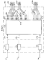
- the node ND represented in FIG. 1 connects N inputs I1, ..., Ij, ..., IN to N 'outputs connected to links grouped into any groups: LG1, ........, LGk. Each group can be broken down into a certain number of regular subgroups, a regular subgroup can possibly consist of a single output.
- a cell is intended for a single group of outputs: LG1 for example.
- This cell is routed into the ND node based on internal routing information contained in an internal routing label which is associated with the cell when it enters the node.
- This internal routing information is derived from external routing information which can be implicit (rank of the cell in a time multiplexing) or explicit (virtual circuit or virtual beam identifier).
- the external routing data designating a communication must be converted into an internal routing label by means of a translation, since the fact that the group is irregular prevents this output address from being fully determined by calculation.
- This translation can be done: either in a single step, in a first stage of the node, before the entry in a first stage of switching elements; either in several stages, in the different stages of switching elements; either by combining these two processes.
- a switching node according to the invention comprises a first stage which selects, predetermined labels, a label identifying a regular subgroup of outputs of the node, optionally comprising a single output, according to an algorithm which is a function of the rank of the input receiving the cell considered, and preferably which is also a function of the time when this cell is received.
- any cell which is intended for one of the link groups LG1, ..., LGk can be sent on any of the outputs OP1, ..., OPN connected to one of the bonds of this group.
- LG1 This breakdown of group LG1 is well suited for a switching network having the capacity to route to a subgroup of outputs having addresses linked by a mathematical relationship, or having only the capacity to route to a subgroup of outputs having consecutive addresses, but not suitable if the SN network only has the capacity for single-route routing, that is to say to a single output. In such a case, the LG1 group must be broken down into regular subgroups, each consisting of a single output.
- Figures 2, 3, 4, 5, 6 illustrate four examples of distribution from a cell to an output of an irregular group of outputs, according to the capacities of the switching network SN.
- the first stage of the ND node, made up of translation devices, is not shown. It provides, for each cell, different internal routing data in the four cases represented.
- connection network SN is referenced SN1, SN2, SN3, SN4, because it does not have the same capacities.
- it has three stages S1, S2, S3 having a regular topology. Only the example shown in FIG. 4 comprises an additional stage S4 allowing the random distribution of cells on a cluster of outputs.
- the stage S1 consists of 8 input planes PI1 to PI8 each comprising 8 elementary switches S11, ..., S18.
- the stages S2 and S3 are located on eight output planes PO1, ..., PO8 which each carry 16 elementary switches, namely 8 elementary switches S21, ..., S28 for the stage S2, and 8 elementary switches S31, ..., S38 for stage S3.
- Each basic switch has 32 inputs and 32 outputs.
- the 32 outputs of each elementary switch of stages S1 and S2 are organized into 8 groups OL1, ..., OL8 of four outputs, each group being connected to a bundle of four links internal to the connection network.
- each elementary switch of stages S2 and S3 are organized into eight groups of four inputs.
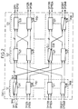
- the node has a connection network SN1 which only has the possibility of single-route routing.
- a cell is routed along a path that is fully determined when an internal routing label is associated with that cell.
- the recipient output is therefore also determined at the same time.
- a group of outputs, regular or irregular is broken down at the input of the node into subgroups comprising only one output.
- the translation device selects a label from among labels consisting respectively of the addresses of the outputs constituting this group.
- the internal routing label consisting of an output address, OPA then comprises several sets of bits, each set identifying an output of an elementary switch through which the cell must pass.
- OPA an output address of an output of the connection network SN, is made up of three sets of bits.
- FIG. 2 shows in strong lines the transmission of a cell from the input IP1 of the network SN to a single output OP2048 of the network SN1.
- a first set of bits of the label comprises three bits identifying one of the eight outputs OL1, ..., OL8 of the switch S11 of the plane PI1 of the first stage.
- a second set comprising three bits identifies one of the eight outputs OL1, ..., OL8 of the elementary switch S21 of the plane PO8.
- a third set comprising five bits identifies one of the 32 outputs OP2017, ..., OP2048 of the elementary switch S38 of the plane PO8.
- the output address OPA therefore comprises 11 bits in total, which make it possible to define a route to one of the 2048 outputs of the connection network SN1.
- the output address OPA is 111, 111, 11111, for routing a cell by: the output OL8 of the elementary switch S11 of stage S1; then the output OL8 of the elementary switch S21 in stage S2, of the plane PO8; and finally the 32nd output of the switch S38 of the stage S3 in the plane PO8; this output constituting the output OP2048 of the network SN.
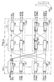
- the node comprises a connection network SN2 having the single-path routing capacity, increased by the distribution capacity over a cluster of outputs.
- a group of outputs is broken down into regular subgroups which are all clusters, in order to take advantage of the capacities of the SN2 network.
- a cluster can possibly only have one output.
- the translation circuit translates the virtual circuit or virtual bundle identity into an output cluster address, OPCA.
- this embodiment SN2 comprises an additional stage S4 which comprises, in each switching plane PO1, ..., PO8, switching elements, S41, ..., S48, of known type , to make a random selection within this cluster.
- the characteristics of the switching elements S41, ..., S48 limit the number of outputs per cluster to 32.
- the switching elements S41, ..., S48 can consist, for example, of a common queue with 32 outputs and an output server which successively reads the cells waiting in the queue and distributes them randomly on 32 outputs.
- the label OPCA allows the switches S11, S21, S31 to route a cell along a single path to a single output of the switching element S31 of the plane PO8. Then the switching element S48 of the plane PO8 performs the random selection of an output from the sixteen outputs OP1800, .., OP1815, constituting the cluster designated by OPCA.
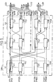
- the node comprises a network SN3, having the possibility of multi-route routing towards a regular output group, not necessarily made up of outputs having consecutive addresses.
- the same regular group can include a number of outputs which can go up to the total number (2048) of outputs of the node SN3.
- Each irregular group can therefore be broken down into several regular sub-groups, without limitation of the number of exits in each sub-group.
- the translation circuit translates a virtual circuit and virtual bundle identifier into a label consisting of a regular subgroup address, OPSGA, selected from two labels, because this irregular group can be broken down into 2 sub - regular groups, SGA and SGB. These subgroups are not clusters because the outputs do not have consecutive addresses.
- the label OPSA designates SGB and allows the elementary switches S21, and S31, ..., S38 of the plane PO8 to randomly select an output from all the outputs of the SGB subgroup.
- the addresses are of the form 1761 + K * 32
- the random selection in the elementary switches S21 and S31, ..., S38 of PO8 transfers the cell to the output OP1824 of the subgroup SGB.
- the other paths leading to the group's unselected exits are shown in strong dotted lines.
- the node according to the invention is compatible with the broadcasting of a cell to several destinations possibly consisting of irregular groups of outputs.
- each translation circuit selects an internal self-routing label which consists of the identity of a distribution tree making it possible to route, for each destination, a copy of this cell to a subgroup. regular group of irregular group constituting this destination.
- the case where the destination is a single exit and the case where the destination is a single group of regular exits are special cases which can easily be deduced from the general case where the destinations are made up of several irregular groups.
- at least one switching element of the switching network must be able to broadcast a cell according to the broadcasting tree identified by the internal auto-routing label. Such a switching element identifies at least one output among the outputs of this element, as a function of the diffusion tree identified by the internal routing label associated with the cell; and it emits a copy of this cell on each of the outputs thus identified.
- Figures 5 and 6 show the same block diagram as Figure 2, but the switching elements are all capable of performing broadcast routing.
- Figures 5 and 6 illustrate its operation in the case of the broadcasting of a cell to three destinations which are three groups of outputs LG1, LG2, LG3. In each of these figures a diffusion tree is shown in strong lines.
- a cell is applied to the IP1 input with an internal routing label constituted by the identity A1 of a broadcasting tree making it possible to route: a first copy of this cell to a regular subgroup SG1a of the irregular output group LG1, a second copy of this cell to the regular subgroup SG2c of the irregular group LG2, and a third copy of this cell to a regular subgroup SG3b of the irregular group LG3.
- the three copies of the cell are created in the switching element S11 of the plane PI1 of the first switching stage S1. These three copies are issued on three outputs of this switching element S11 allowing access respectively to the subgroups SG1a, SG2c, SG3b.
- the first copy passes through the switching elements S21 and S31 of the plane PO1.
- the switching element S31 distributes within the SG1a subgroup. It therefore randomly chooses an output from the outputs of the SG1a subgroup and re-issues the first copy on this output.
- the other selection possibilities by the switching element S31 are shown in dotted lines in the figure. An output is selected within the SG2c subgroup, and an output is selected within the SG3b subgroup, analogously by switching elements which are not shown in the figure.
- FIG. 6 illustrates the operation of the same node when a cell is applied to the same input I1 with an internal routing label constituted by the identity A2 of another distribution tree making it possible to route three copies from this cell respectively to a regular subgroup SG1c of the irregular group LG1, a regular subgroup SG2b of the irregular group LG2, and a regular subgroup SG3c of the irregular group LG3.
- the three copies of the cell are still created in the switching element S11 of the plane PI1 but they follow different paths compared to the previous example.
- the first copy is sent on an output of the regular subgroup SG1c which is chosen randomly by the switch S38 of the plane PO1.
- the second copy is transmitted on an output among the outputs of the regular subgroup SG2b by a switching element which is not represented.
- the third copy is transmitted on an output chosen randomly, by the switching element S38 of the plane P08, among the outputs of the regular subgroup SG3c.
- the number of diffusion trees A1, A2, ... which are predetermined for diffusing a cell from the input IP1 to the three groups LG1, LG2, LG3, is equal to the number of combinations of three subgroups, achievable by taking a subgroup from each of the LG1, LG2, LG3 groups.
- a switching network having the capacity for multi-route auto-routing with group routing and broadcasting is described for example in European patent application No. 91-101915.5
- the memory M2j is addressed both by the value LGi and by a value t supplied by a clock H1.
- the clock H1 supplies a series of values, at a rhythm corresponding to the rhythm of reception of the cells on each input I1 ... IN, and with a modulo T which is equal, for example, to 128 times the duration of a cell.
- a multiplexer MX1 collects the OPA value provided by all of the columns. This value OPA constitutes the internal routing label OPA which is supplied to the input IPj of the network SN, at the same time as the cell considered.
- FIG. 8 represents a second example Tj ′ of a translation device for determining an internal routing label, without explicit determination of the address LGi of the group of outputs destined for the cell considered. It no longer has memories M1 for determining the address LGi, but it does have a memory M3j addressed simultaneously by the value of the identities VCI-VPI and by the value t supplied by a clock H2 analogous to the clock H1 described above.
- An MX2 multiplexer collects the OPA value provided by all the columns of M3j memory. This value OPA constitutes the value of the internal routing label, OPA, which is supplied to the input IPj of the connection network SN.
- the table below represents the content of the different memories M21, ..., M2N, or M31, ..., M3N, by limiting itself to a single line corresponding to a given group which has only three outputs: L1, L2 , L3; the modulo T of the clock is equal to 128 times the duration of a cell; and the number N of connections of the connection network SN is equal to 16.
- the number of exits in the LGi group is not a sub-multiple of 128, the outputs do not all appear with the same number of times in this table. In other words, the distribution of the cells is not absolutely regular between the three outputs. However, the differences remain minimal since each exit appears only once more, at worst, than the other exits, for the whole of this table.
- the identities of the outputs L1, L2, L3 are distributed, as regularly as possible, in the table by incrementing the index i of the output Li for each incrementation by a unit of time, in filling the lines successively.
- the modulo T is not a multiple of the number, 3, of the outputs constituting the group, there is a shift of the output identities for each incrementation of a unit of rank j of the input Ij having received the cell considered .
- This offset as a function of the instant of reception of a cell and as a function of the rank having received this cell, is sufficient to ensure a temporal decorrelation and a spatial decorrelation of the cells.
- the following table represents the content of a single line of memories M21, ..., M2N or M31, ..., M3N, limited to a given group, which has 259 outputs: L1, ..., L259.
- the modulo T of the clock is equal to 128 times the duration of a cell.
- modulo 259 which is the number of outputs constituting the group.
- the number of outputs that the group comprises is greater than the number of time units counted by the clock, therefore during T clock periods certain outputs belonging to the group are never used for cells arriving at an input having a given rank j value.
- the following table gives the content of the lines of memories M21, ..., M2N corresponding to the group L1, ..., L259, when this example of algorithm is used.
- Examples of output selection algorithm described above increment the output address by one unit for each unit of elapsed time and for each unit of the rank of the input considered.
- the time variable t can be replaced by any random number changing dynamically, ensuring that the different values of this random number have the same statistical probability.
- the internal routing label is selected from predetermined labels, some of which identify a regular subgroup comprising several outputs, having addresses consecutive or not.
- the translation devices shown in FIGS. 7 and 8 are identical, only the meaning of the content of memories M2j and M3j changes.
- the address of a single output, OPA is replaced by an address common to several outputs. This address is noted OPCA if these outputs have consecutive addresses, and OPSGA if they are addresses linked by another mathematical relation.
- a broadcast tree identity can be stored in place of an OPA output address.
- This weighting can consist in storing in memory a list of output addresses, or addresses of subgroups, or tree identities, in which some of them are duplicated several times to multiply their chances of be selected. Those with the minimum bandwidth only appear once in the list. Those with a bandwidth equal to twice the minimum bandwidth appear twice in the list, etc.
Landscapes
- Engineering & Computer Science (AREA)
- Computer Networks & Wireless Communication (AREA)
- Signal Processing (AREA)
- Physics & Mathematics (AREA)
- Mathematical Physics (AREA)
- Data Exchanges In Wide-Area Networks (AREA)
- Use Of Switch Circuits For Exchanges And Methods Of Control Of Multiplex Exchanges (AREA)
Applications Claiming Priority (2)
| Application Number | Priority Date | Filing Date | Title |
|---|---|---|---|
| FR9303763 | 1993-03-31 | ||
| FR9303763A FR2703545B1 (fr) | 1993-03-31 | 1993-03-31 | NÓoeud de commutation asynchrone distribuant dynamiquement des cellules vers des sorties constituant un groupe dit irrégulier . |
Publications (2)
| Publication Number | Publication Date |
|---|---|
| EP0618705A1 true EP0618705A1 (de) | 1994-10-05 |
| EP0618705B1 EP0618705B1 (de) | 2000-05-03 |
Family
ID=9445575
Family Applications (1)
| Application Number | Title | Priority Date | Filing Date |
|---|---|---|---|
| EP94400660A Expired - Lifetime EP0618705B1 (de) | 1993-03-31 | 1994-03-28 | Asynchrone Vermittlungsstelle zur dynamischen Verteilung der Zellen an eine nicht-reguläre Gruppe der Ausgänge |
Country Status (7)
| Country | Link |
|---|---|
| US (1) | US5461615A (de) |
| EP (1) | EP0618705B1 (de) |
| JP (1) | JP3434874B2 (de) |
| CA (1) | CA2120291A1 (de) |
| DE (1) | DE69424216T2 (de) |
| ES (1) | ES2146248T3 (de) |
| FR (1) | FR2703545B1 (de) |
Cited By (1)
| Publication number | Priority date | Publication date | Assignee | Title |
|---|---|---|---|---|
| EP0909061A3 (de) * | 1997-10-13 | 1999-12-15 | Fujitsu Limited | Übertragungsgerät und Lastverteilungsübertragungsverfahren im Übertragungsgerät |
Families Citing this family (39)
| Publication number | Priority date | Publication date | Assignee | Title |
|---|---|---|---|---|
| DE69534231T2 (de) * | 1995-11-07 | 2006-01-19 | Alcatel | Verfahren und Einrichtung zur Verwaltung von Mehrfachverbindungen |
| US5771234A (en) * | 1995-12-06 | 1998-06-23 | Industrial Technology Research Institute | Method and system for ATM cell multiplexing under constant bit rate, variable bit rate and best-effort traffic |
| US5812526A (en) * | 1995-12-21 | 1998-09-22 | Industrial Technology Research Institute | Traffic control mechanism in ATM communications network |
| US6188690B1 (en) * | 1996-12-12 | 2001-02-13 | Pmc-Sierra, Inc. | Method and apparatus for high speed, scalable communication system |
| US6052376A (en) * | 1996-12-30 | 2000-04-18 | Hyundai Electronics America | Distributed buffering system for ATM switches |
| US5987028A (en) * | 1997-05-12 | 1999-11-16 | Industrial Technology Research Insitute | Multiple channel ATM switch |
| US5940389A (en) * | 1997-05-12 | 1999-08-17 | Computer And Communication Research Laboratories | Enhanced partially self-routing algorithm for controller Benes networks |
| JPH1155283A (ja) * | 1997-08-06 | 1999-02-26 | Fujitsu Ltd | Atm交換機 |
| DE19741577A1 (de) * | 1997-09-20 | 1999-03-25 | Cit Alcatel | Verfahren und Vorrichtungen zum Aufbau von Punkt-zu-Mehrpunkt-Verbindungen und Mehrpunkt-zu-Punkt-Verbindugen |
| US6363077B1 (en) * | 1998-02-13 | 2002-03-26 | Broadcom Corporation | Load balancing in link aggregation and trunking |
| US6359879B1 (en) * | 1998-04-24 | 2002-03-19 | Avici Systems | Composite trunking |
| US7382736B2 (en) | 1999-01-12 | 2008-06-03 | Mcdata Corporation | Method for scoring queued frames for selective transmission through a switch |
| EP1178633A1 (de) * | 2000-08-02 | 2002-02-06 | Siemens Aktiengesellschaft | Kanalbündelsystem und Vermittlungseinrichtung |
| US7356030B2 (en) * | 2000-11-17 | 2008-04-08 | Foundry Networks, Inc. | Network switch cross point |
| US7236490B2 (en) | 2000-11-17 | 2007-06-26 | Foundry Networks, Inc. | Backplane interface adapter |
| US7596139B2 (en) | 2000-11-17 | 2009-09-29 | Foundry Networks, Inc. | Backplane interface adapter with error control and redundant fabric |
| US7002980B1 (en) * | 2000-12-19 | 2006-02-21 | Chiaro Networks, Ltd. | System and method for router queue and congestion management |
| US8051199B2 (en) * | 2001-06-08 | 2011-11-01 | The University Of Hong Kong | Self-routing address assignment in packet-switched networks |
| DE10217856B4 (de) * | 2002-04-22 | 2006-11-02 | Infineon Technologies Ag | Telekommunikationsnetz und Verfahren zum Übertragen von Daten in einem Telekommunikationsnetz |
| US7187687B1 (en) | 2002-05-06 | 2007-03-06 | Foundry Networks, Inc. | Pipeline method and system for switching packets |
| US7468975B1 (en) | 2002-05-06 | 2008-12-23 | Foundry Networks, Inc. | Flexible method for processing data packets in a network routing system for enhanced efficiency and monitoring capability |
| US20120155466A1 (en) | 2002-05-06 | 2012-06-21 | Ian Edward Davis | Method and apparatus for efficiently processing data packets in a computer network |
| US7266117B1 (en) | 2002-05-06 | 2007-09-04 | Foundry Networks, Inc. | System architecture for very fast ethernet blade |
| US7649885B1 (en) | 2002-05-06 | 2010-01-19 | Foundry Networks, Inc. | Network routing system for enhanced efficiency and monitoring capability |
| US6901072B1 (en) | 2003-05-15 | 2005-05-31 | Foundry Networks, Inc. | System and method for high speed packet transmission implementing dual transmit and receive pipelines |
| US7447223B2 (en) * | 2004-01-28 | 2008-11-04 | Hewlett-Packard Development Company, L.P. | Switching mesh with broadcast path redundancy |
| US7817659B2 (en) | 2004-03-26 | 2010-10-19 | Foundry Networks, Llc | Method and apparatus for aggregating input data streams |
| US8730961B1 (en) | 2004-04-26 | 2014-05-20 | Foundry Networks, Llc | System and method for optimizing router lookup |
| US7657703B1 (en) | 2004-10-29 | 2010-02-02 | Foundry Networks, Inc. | Double density content addressable memory (CAM) lookup scheme |
| US8448162B2 (en) | 2005-12-28 | 2013-05-21 | Foundry Networks, Llc | Hitless software upgrades |
| US7903654B2 (en) | 2006-08-22 | 2011-03-08 | Foundry Networks, Llc | System and method for ECMP load sharing |
| US8238255B2 (en) | 2006-11-22 | 2012-08-07 | Foundry Networks, Llc | Recovering from failures without impact on data traffic in a shared bus architecture |
| US7978614B2 (en) | 2007-01-11 | 2011-07-12 | Foundry Network, LLC | Techniques for detecting non-receipt of fault detection protocol packets |
| US8271859B2 (en) | 2007-07-18 | 2012-09-18 | Foundry Networks Llc | Segmented CRC design in high speed networks |
| US8037399B2 (en) | 2007-07-18 | 2011-10-11 | Foundry Networks, Llc | Techniques for segmented CRC design in high speed networks |
| US8149839B1 (en) | 2007-09-26 | 2012-04-03 | Foundry Networks, Llc | Selection of trunk ports and paths using rotation |
| US8190881B2 (en) | 2007-10-15 | 2012-05-29 | Foundry Networks Llc | Scalable distributed web-based authentication |
| US8090901B2 (en) | 2009-05-14 | 2012-01-03 | Brocade Communications Systems, Inc. | TCAM management approach that minimize movements |
| US8599850B2 (en) | 2009-09-21 | 2013-12-03 | Brocade Communications Systems, Inc. | Provisioning single or multistage networks using ethernet service instances (ESIs) |
Citations (2)
| Publication number | Priority date | Publication date | Assignee | Title |
|---|---|---|---|---|
| EP0446540A1 (de) * | 1990-03-14 | 1991-09-18 | Alcatel N.V. | Selbstleitweglenkendes Mehrwege-Vermittlungsnetzwerk zum Vermittlen von Zellen mit asynchroner Zeitvielfachübermittlung |
| EP0524350A1 (de) * | 1991-07-22 | 1993-01-27 | Alcatel N.V. | Telekommunikationssystem zur Übertragung von Nachrichtenzellen durch Vermittlungsknoten, die über Gruppen Übertragungsleitungen miteinander verbunden sind |
Family Cites Families (2)
| Publication number | Priority date | Publication date | Assignee | Title |
|---|---|---|---|---|
| US5303078A (en) * | 1990-12-18 | 1994-04-12 | Bell Communications Research, Inc. | Apparatus and method for large scale ATM switching |
| US5130984A (en) * | 1990-12-18 | 1992-07-14 | Bell Communications Research, Inc. | Large fault tolerant packet switch particularly suited for asynchronous transfer mode (ATM) communication |
-
1993
- 1993-03-31 FR FR9303763A patent/FR2703545B1/fr not_active Expired - Fee Related
-
1994
- 1994-03-28 ES ES94400660T patent/ES2146248T3/es not_active Expired - Lifetime
- 1994-03-28 EP EP94400660A patent/EP0618705B1/de not_active Expired - Lifetime
- 1994-03-28 DE DE69424216T patent/DE69424216T2/de not_active Expired - Fee Related
- 1994-03-29 US US08/219,712 patent/US5461615A/en not_active Expired - Lifetime
- 1994-03-30 CA CA002120291A patent/CA2120291A1/fr not_active Abandoned
- 1994-03-31 JP JP06285394A patent/JP3434874B2/ja not_active Expired - Fee Related
Patent Citations (3)
| Publication number | Priority date | Publication date | Assignee | Title |
|---|---|---|---|---|
| EP0446540A1 (de) * | 1990-03-14 | 1991-09-18 | Alcatel N.V. | Selbstleitweglenkendes Mehrwege-Vermittlungsnetzwerk zum Vermittlen von Zellen mit asynchroner Zeitvielfachübermittlung |
| FR2659819A1 (fr) * | 1990-03-14 | 1991-09-20 | Alcatel Nv | Reseau de commutation a trajets multiples et a autoacheminement pour la commutation de cellules a multiplexage temporel asynchrone. |
| EP0524350A1 (de) * | 1991-07-22 | 1993-01-27 | Alcatel N.V. | Telekommunikationssystem zur Übertragung von Nachrichtenzellen durch Vermittlungsknoten, die über Gruppen Übertragungsleitungen miteinander verbunden sind |
Non-Patent Citations (1)
| Title |
|---|
| SCHRODI ET AL, INT. SWITCHING SYMPOSIUM 92, vol. 2, 25 October 1992 (1992-10-25), JAPAN, pages 156 - 160, XP000337713 * |
Cited By (2)
| Publication number | Priority date | Publication date | Assignee | Title |
|---|---|---|---|---|
| EP0909061A3 (de) * | 1997-10-13 | 1999-12-15 | Fujitsu Limited | Übertragungsgerät und Lastverteilungsübertragungsverfahren im Übertragungsgerät |
| US6377584B1 (en) | 1997-10-13 | 2002-04-23 | Fujitsu Limited | Transmission equipment and a load-distribution transmitting method in the transmission equipment |
Also Published As
| Publication number | Publication date |
|---|---|
| JP3434874B2 (ja) | 2003-08-11 |
| FR2703545A1 (fr) | 1994-10-07 |
| FR2703545B1 (fr) | 1995-05-12 |
| EP0618705B1 (de) | 2000-05-03 |
| CA2120291A1 (fr) | 1994-10-01 |
| ES2146248T3 (es) | 2000-08-01 |
| DE69424216D1 (de) | 2000-06-08 |
| JPH077513A (ja) | 1995-01-10 |
| DE69424216T2 (de) | 2000-12-28 |
| US5461615A (en) | 1995-10-24 |
Similar Documents
| Publication | Publication Date | Title |
|---|---|---|
| EP0618705B1 (de) | Asynchrone Vermittlungsstelle zur dynamischen Verteilung der Zellen an eine nicht-reguläre Gruppe der Ausgänge | |
| EP0446540B1 (de) | Selbstleitweglenkendes Mehrwege-Vermittlungsnetzwerk zum Vermittlen von Zellen mit asynchroner Zeitvielfachübermittlung | |
| EP0609137B1 (de) | Umwandlungsvorrichtung zwischen Asynchronen- und Synchronen Übertragungsverfahren | |
| EP0601653B1 (de) | System zur Übertragung von Information mit unterschiedlichen Bitraten und Sendestation für ein solches System | |
| FR2666472A1 (fr) | Systeme de memorisation temporaire d'information comprenant une memoire tampon enregistrant des donnees en blocs de donnees de longueur fixe ou variable. | |
| EP0735727B1 (de) | ATM Vermittler mit Verwendung eines synchronen Gruppenvermittlungsverfahrens | |
| EP0497667B1 (de) | Optische Schaltmatrix | |
| EP0771132B1 (de) | Anlage zur Regulierung des ATM-Zellenflusses in einer ATM-Vermittlungsstelle | |
| FR2727818A1 (fr) | Procede d'acheminement de cellules dans un reseau de commutation a multiplexage temporel asynchrone, reseau, commutateur d'entree et application correspondants | |
| WO1995035613A1 (fr) | Procede et dispositifs pour l'acheminement de paquets de donnees dans un reseau multisite | |
| EP0587468A2 (de) | Photonisches Verbindungsnetz mit Rundschreibfähigkeit | |
| FR2549673A1 (fr) | Commutateur elementaire pour autocommutateur utilisant une technique de multiplexage asynchrone | |
| EP0750442B1 (de) | Methode und System für die integrale Vermittlung von leitungsvermitteltem und paketvermitteltem Verkehr | |
| FR2774242A1 (fr) | Systeme et procede de commutation asynchrone de cellules composites, et modules de port d'entree et de port de sortie correspondants | |
| EP0323928A1 (de) | Datenpaketevermittlungsverfahren und Vorrichtung zum Ausführen desselben | |
| EP0899917A1 (de) | Vorrichtung und Verfahren zur ATM-Gruppenvermittlung mit Zugehörigen Endfunktionen im Eingang und Ausgang | |
| EP0689319B1 (de) | Wegesucheapparat für ATM-Zellen | |
| FR2703546A1 (fr) | NÓoeud de commutation asynchrone distribuant dynamiquement des cellules vers des liaisons sortantes connectées à des ports de sortie constituant un groupe dit irrégulier. | |
| EP0091338B1 (de) | Erweiterte modulare digitale Telefonvermittlung | |
| Vishwanath et al. | On-line multicast routing in WDM grooming networks | |
| EP0403361A1 (de) | Verfahren und System zur Zellenvermittlung für asynchrone Zeitvielfachvermittlungen | |
| EP0497669A1 (de) | Optische Ortsvermittlungsanlage | |
| FR2470495A1 (fr) | Systeme de commutation numerique de telecommunications capable d'etablir des connexions multilaterales de teleconference et de diffusion selective d'informations ou de signaux | |
| FR2802742A1 (fr) | Systeme et procede de commutation de donnees | |
| FR2778296A1 (fr) | Procede et dispositif de communication, de transmission et/ou de reception d'information |
Legal Events
| Date | Code | Title | Description |
|---|---|---|---|
| PUAI | Public reference made under article 153(3) epc to a published international application that has entered the european phase |
Free format text: ORIGINAL CODE: 0009012 |
|
| AK | Designated contracting states |
Kind code of ref document: A1 Designated state(s): DE ES FR GB IT NL |
|
| 17P | Request for examination filed |
Effective date: 19950126 |
|
| 17Q | First examination report despatched |
Effective date: 19980612 |
|
| GRAG | Despatch of communication of intention to grant |
Free format text: ORIGINAL CODE: EPIDOS AGRA |
|
| GRAG | Despatch of communication of intention to grant |
Free format text: ORIGINAL CODE: EPIDOS AGRA |
|
| GRAH | Despatch of communication of intention to grant a patent |
Free format text: ORIGINAL CODE: EPIDOS IGRA |
|
| GRAH | Despatch of communication of intention to grant a patent |
Free format text: ORIGINAL CODE: EPIDOS IGRA |
|
| RBV | Designated contracting states (corrected) |
Designated state(s): DE ES FR GB IT NL |
|
| RAP1 | Party data changed (applicant data changed or rights of an application transferred) |
Owner name: ALCATEL |
|
| GRAA | (expected) grant |
Free format text: ORIGINAL CODE: 0009210 |
|
| AK | Designated contracting states |
Kind code of ref document: B1 Designated state(s): DE ES FR GB IT NL |
|
| REF | Corresponds to: |
Ref document number: 69424216 Country of ref document: DE Date of ref document: 20000608 |
|
| ITF | It: translation for a ep patent filed | ||
| GBT | Gb: translation of ep patent filed (gb section 77(6)(a)/1977) |
Effective date: 20000526 |
|
| REG | Reference to a national code |
Ref country code: ES Ref legal event code: FG2A Ref document number: 2146248 Country of ref document: ES Kind code of ref document: T3 |
|
| PLBE | No opposition filed within time limit |
Free format text: ORIGINAL CODE: 0009261 |
|
| STAA | Information on the status of an ep patent application or granted ep patent |
Free format text: STATUS: NO OPPOSITION FILED WITHIN TIME LIMIT |
|
| 26N | No opposition filed | ||
| REG | Reference to a national code |
Ref country code: GB Ref legal event code: IF02 |
|
| PGFP | Annual fee paid to national office [announced via postgrant information from national office to epo] |
Ref country code: NL Payment date: 20020228 Year of fee payment: 9 |
|
| PG25 | Lapsed in a contracting state [announced via postgrant information from national office to epo] |
Ref country code: NL Free format text: LAPSE BECAUSE OF NON-PAYMENT OF DUE FEES Effective date: 20031001 |
|
| NLV4 | Nl: lapsed or anulled due to non-payment of the annual fee |
Effective date: 20031001 |
|
| PGFP | Annual fee paid to national office [announced via postgrant information from national office to epo] |
Ref country code: DE Payment date: 20070316 Year of fee payment: 14 |
|
| PGFP | Annual fee paid to national office [announced via postgrant information from national office to epo] |
Ref country code: GB Payment date: 20070322 Year of fee payment: 14 |
|
| PGFP | Annual fee paid to national office [announced via postgrant information from national office to epo] |
Ref country code: ES Payment date: 20070329 Year of fee payment: 14 |
|
| REG | Reference to a national code |
Ref country code: FR Ref legal event code: CD |
|
| PGFP | Annual fee paid to national office [announced via postgrant information from national office to epo] |
Ref country code: IT Payment date: 20070626 Year of fee payment: 14 |
|
| PGFP | Annual fee paid to national office [announced via postgrant information from national office to epo] |
Ref country code: FR Payment date: 20070319 Year of fee payment: 14 |
|
| GBPC | Gb: european patent ceased through non-payment of renewal fee |
Effective date: 20080328 |
|
| REG | Reference to a national code |
Ref country code: FR Ref legal event code: ST Effective date: 20081125 |
|
| PG25 | Lapsed in a contracting state [announced via postgrant information from national office to epo] |
Ref country code: DE Free format text: LAPSE BECAUSE OF NON-PAYMENT OF DUE FEES Effective date: 20081001 |
|
| PG25 | Lapsed in a contracting state [announced via postgrant information from national office to epo] |
Ref country code: FR Free format text: LAPSE BECAUSE OF NON-PAYMENT OF DUE FEES Effective date: 20080331 |
|
| REG | Reference to a national code |
Ref country code: ES Ref legal event code: FD2A Effective date: 20080329 |
|
| PG25 | Lapsed in a contracting state [announced via postgrant information from national office to epo] |
Ref country code: GB Free format text: LAPSE BECAUSE OF NON-PAYMENT OF DUE FEES Effective date: 20080328 |
|
| PG25 | Lapsed in a contracting state [announced via postgrant information from national office to epo] |
Ref country code: ES Free format text: LAPSE BECAUSE OF NON-PAYMENT OF DUE FEES Effective date: 20080329 |
|
| PG25 | Lapsed in a contracting state [announced via postgrant information from national office to epo] |
Ref country code: IT Free format text: LAPSE BECAUSE OF NON-PAYMENT OF DUE FEES Effective date: 20080328 |