EP0618761B1 - Procédé et dispositif de fixation d'un détecteur optique d'un appareil tel qu'un télécopieur - Google Patents
Procédé et dispositif de fixation d'un détecteur optique d'un appareil tel qu'un télécopieur Download PDFInfo
- Publication number
- EP0618761B1 EP0618761B1 EP94400633A EP94400633A EP0618761B1 EP 0618761 B1 EP0618761 B1 EP 0618761B1 EP 94400633 A EP94400633 A EP 94400633A EP 94400633 A EP94400633 A EP 94400633A EP 0618761 B1 EP0618761 B1 EP 0618761B1
- Authority
- EP
- European Patent Office
- Prior art keywords
- frame
- card
- plane
- plate
- substantially perpendicular
- Prior art date
- Legal status (The legal status is an assumption and is not a legal conclusion. Google has not performed a legal analysis and makes no representation as to the accuracy of the status listed.)
- Expired - Lifetime
Links
- 230000003287 optical effect Effects 0.000 title claims description 12
- 238000000034 method Methods 0.000 title claims description 6
- 230000006835 compression Effects 0.000 description 2
- 238000007906 compression Methods 0.000 description 2
- 230000003071 parasitic effect Effects 0.000 description 2
- 238000005452 bending Methods 0.000 description 1
- 238000006073 displacement reaction Methods 0.000 description 1
- 230000000284 resting effect Effects 0.000 description 1
Images
Classifications
-
- H—ELECTRICITY
- H04—ELECTRIC COMMUNICATION TECHNIQUE
- H04N—PICTORIAL COMMUNICATION, e.g. TELEVISION
- H04N1/00—Scanning, transmission or reproduction of documents or the like, e.g. facsimile transmission; Details thereof
- H04N1/024—Details of scanning heads ; Means for illuminating the original
- H04N1/028—Details of scanning heads ; Means for illuminating the original for picture information pick-up
- H04N1/03—Details of scanning heads ; Means for illuminating the original for picture information pick-up with photodetectors arranged in a substantially linear array
-
- F—MECHANICAL ENGINEERING; LIGHTING; HEATING; WEAPONS; BLASTING
- F16—ENGINEERING ELEMENTS AND UNITS; GENERAL MEASURES FOR PRODUCING AND MAINTAINING EFFECTIVE FUNCTIONING OF MACHINES OR INSTALLATIONS; THERMAL INSULATION IN GENERAL
- F16B—DEVICES FOR FASTENING OR SECURING CONSTRUCTIONAL ELEMENTS OR MACHINE PARTS TOGETHER, e.g. NAILS, BOLTS, CIRCLIPS, CLAMPS, CLIPS OR WEDGES; JOINTS OR JOINTING
- F16B5/00—Joining sheets or plates, e.g. panels, to one another or to strips or bars parallel to them
- F16B5/02—Joining sheets or plates, e.g. panels, to one another or to strips or bars parallel to them by means of fastening members using screw-thread
-
- H—ELECTRICITY
- H05—ELECTRIC TECHNIQUES NOT OTHERWISE PROVIDED FOR
- H05K—PRINTED CIRCUITS; CASINGS OR CONSTRUCTIONAL DETAILS OF ELECTRIC APPARATUS; MANUFACTURE OF ASSEMBLAGES OF ELECTRICAL COMPONENTS
- H05K7/00—Constructional details common to different types of electric apparatus
- H05K7/14—Mounting supporting structure in casing or on frame or rack
- H05K7/1417—Mounting supporting structure in casing or on frame or rack having securing means for mounting boards, plates or wiring boards
- H05K7/142—Spacers not being card guides
-
- H—ELECTRICITY
- H04—ELECTRIC COMMUNICATION TECHNIQUE
- H04N—PICTORIAL COMMUNICATION, e.g. TELEVISION
- H04N2201/00—Indexing scheme relating to scanning, transmission or reproduction of documents or the like, and to details thereof
- H04N2201/024—Indexing scheme relating to scanning, transmission or reproduction of documents or the like, and to details thereof deleted
- H04N2201/02452—Arrangements for mounting or supporting elements within a scanning head
- H04N2201/02454—Element mounted or supported
- H04N2201/02456—Scanning element, e.g. CCD array, photodetector
-
- H—ELECTRICITY
- H04—ELECTRIC COMMUNICATION TECHNIQUE
- H04N—PICTORIAL COMMUNICATION, e.g. TELEVISION
- H04N2201/00—Indexing scheme relating to scanning, transmission or reproduction of documents or the like, and to details thereof
- H04N2201/024—Indexing scheme relating to scanning, transmission or reproduction of documents or the like, and to details thereof deleted
- H04N2201/02452—Arrangements for mounting or supporting elements within a scanning head
- H04N2201/02466—Mounting or supporting method
- H04N2201/02468—Mounting or supporting method using screws
-
- H—ELECTRICITY
- H04—ELECTRIC COMMUNICATION TECHNIQUE
- H04N—PICTORIAL COMMUNICATION, e.g. TELEVISION
- H04N2201/00—Indexing scheme relating to scanning, transmission or reproduction of documents or the like, and to details thereof
- H04N2201/024—Indexing scheme relating to scanning, transmission or reproduction of documents or the like, and to details thereof deleted
- H04N2201/02452—Arrangements for mounting or supporting elements within a scanning head
- H04N2201/02479—Mounting or supporting means
Definitions
- the present invention relates to a method and a device for fixing to the frame of an apparatus such as a facsimile machine, a support card for an optical detector with charge transfer circuit.
- a method and such a device are described in EP-A-0 491 500.
- an optical detector such as a CCD strip receives the image of a sheet of paper focused with the aid of an objective, in order to carry out an analysis of this image.
- the optical detector is mounted on a support card, which is itself fixed to the frame of the device perpendicular to the optical axis of the objective.
- the support card for the optical detectors has been fixed to the frame of the device using screws and washers, the screws passing through holes formed in the card and the washers being interposed between the card and the heads of the screw.
- the present invention aims to overcome these drawbacks.
- the invention firstly relates to a method of fixing to the frame of an apparatus such as a facsimile machine, of a support card of an optical detector with charge transfer circuit, characterized by the fact that it includes the step of applying said card to a support surface of said frame using a movable support member substantially perpendicular to the plane of said card and having no freedom to move parallel to it.
- the support member having no freedom of movement in the plane of the support card, the application of the card on the support surface of the frame is carried out only by a force perpendicular to the plane of the card and by therefore without parasitic movement in the plane thereof. This results in optimal adjustment, a simplification of the adjustment operation and therefore a gain in adjustment time.
- the support member is moved substantially perpendicular to the plane of the card by actuation of a rotary clamping member without contact with said card.
- the card is therefore fixed with conventional means such as screws but, due to the absence of contact between these screws and the card, there is no torque during tightening.
- the present invention also relates to a device for fixing to the frame of an apparatus such as a facsimile machine, a support card for an optical detector with charge transfer circuit, characterized in that it comprises a bearing surface formed on said frame and a movable bearing member substantially perpendicular to said bearing surface and having no freedom to move parallel thereto.
- the support member may include an elastic tongue made in one piece with said frame.
- the device according to the invention comprises rotary clamping means for moving said support member substantially perpendicular to said support surface.
- These rotary clamping means can in particular be arranged to pass through the card without friction.
- the rotary clamping means may in particular comprise a screw passing through said support member by cooperating with a nut locked in rotation in a housing formed in the frame.
- the figures show the frame 1 of an apparatus such as a fax machine, this frame carrying in particular a support card 2 of an optical detector constituted for example by a CCD strip (not shown).
- the frame 1 comprises a body forming a bearing surface 3 for the card 2 and, produced in one piece with it, an elastic tongue 4 itself having a bearing zone 5 enabling the card 2 to be pressed against the support surface 3 of the frame 1.
- the tongue 4 has sufficient rigidity in its plane (parallel to the plane of the card 2) to have no freedom of movement other than a bending movement, such that its support zone 5 moves substantially perpendicular to the plane of the card 2 and on the support surface 3.
- a screw 6 has a head 7 resting on the outer surface of the tongue 4 and passes through a hole 8 formed in this tongue and a hole 9 formed in the support card 2.
- the hole 8 has a diameter sufficient to allow the screw 6 to rotate freely, and the hole 9 has an even larger diameter so that, whatever the position of the screw 6 in the hole 8, it has no contact with the edges of hole 9 on plate 2.
- the screw 6 also passes through a hole 10 formed in the body of the frame 1 and its end is engaged in a tightening nut 11 having a shape in square plane and housed in a locking groove 12 of corresponding shape, making it possible to avoid its rotation.
- the card 2 is therefore held in abutment on the bearing surface 3 by tightening the screw 6 which causes the elastic tongue 4 to apply the card to the bearing surface.
- the adjustment of the card 2 in its plane is carried out beforehand, after which the screws 6 are tightened without altering this adjustment.
Landscapes
- Engineering & Computer Science (AREA)
- General Engineering & Computer Science (AREA)
- Microelectronics & Electronic Packaging (AREA)
- Multimedia (AREA)
- Signal Processing (AREA)
- Mechanical Engineering (AREA)
- Facsimile Scanning Arrangements (AREA)
- Facsimiles In General (AREA)
- Facsimile Heads (AREA)
- Mounting And Adjusting Of Optical Elements (AREA)
Description
- La présente invention concerne un procédé et un dispositif de fixation sur le bâti d'un appareil tel qu'un télécopieur, d'une carte support d'un détecteur optique à circuit à transfert de charges. Un tel procédé et un tel dispositif sont décrits dans EP-A-0 491 500.
- Dans un tel appareil, un détecteur optique telle qu'une barrette CCD reçoit l'image d'une feuille de papier focalisée à l'aide d'un objectif, afin d'effectuer une analyse de cette image. Le détecteur optique est monté sur une carte support, elle-même fixée sur le bâti de l'appareil perpendiculairement à l'axe optique de l'objectif.
- Il est donc important, afin de centrer l'image sur le détecteur, de positionner convenablement la carte support dans son propre plan, la mise au point de l'image sur le détecteur s'effectuant indépendamment par translation de l'objectif parallèlement à son axe optique.
- Jusqu'à présent la carte support des détecteurs optiques était fixée sur le bâti de l'appareil à l'aide de vis et de rondelles, les vis traversant des trous formés dans la carte et les rondelles étant interposées entre la carte et les têtes des vis.
- Un tel agencement présentait l'inconvénient que, lors du serrage des vis, un couple de rotation était transmis à la carte par l'intermédiaire de la rondelle, ce qui provoquait un déplacement de la carte dans son plan. Or, un très faible déplacement peu conduire à un décentrage conséquent de l'image étant donné que, dans les barrettes CCD couramment utilisées, la largeur d'un pixel est de l'ordre de 10 micromètres. Le réglage s'effectuait donc par approximations successives sur les différentes vis de serrage. Un tel réglage était donc long et complexe et par conséquent coûteux.
- La présente invention vise à pallier ces inconvénients.
- A cet effet, l'invention a tout d'abord pour objet un procédé de fixation sur le bâti d'un appareil tel qu'un télécopieur, d'une carte support d'un détecteur optique à circuit à transfert de charges, caractérisé par le fait qu'il comprend l'étape consistant à appliquer ladite carte sur une surface d'appui dudit bâti à l'aide d'un organe d'appui mobile sensiblement perpendiculairement au plan de ladite carte et n'ayant pas de liberté de se mouvoir parallèlement à celui-ci.
- L'organe d'appui n'ayant pas de liberté de mouvement dans le plan de la carte support, l'application de la carte sur la surface d'appui du bâti est effectuée uniquement par un effort perpendiculaire au plan de la carte et par conséquent sans mouvement parasite dans le plan de celle-ci. Il en résulte un réglage optimal, une simplification de l'opération de réglage et par conséquent un gain en temps de réglage.
- Dans un mode de mise en oeuvre particulier de l'invention, l'organe d'appui est déplacé sensiblement perpendiculairement au plan de la carte par actionnement d'un organe de serrage rotatif sans contact avec ladite carte.
- La fixation de la carte s'effectue par conséquent avec des moyens conventionnels tels que des vis mais, du fait de l'absence de contact entre ces vis et la carte, celle-ci ne subit aucun couple de rotation lors du serrage.
- La présente invention a également pour objet un dispositif de fixation sur le bâti d'un appareil tel qu'un télécopieur, d'une carte support d'un détecteur optique à circuit à transfert de charges, caractérisé par le fait qu'il comprend une surface d'appui formée sur ledit bâti et un organe d'appui mobile sensiblement perpendiculairement à ladite surface d'appui et n'ayant pas de liberté de se mouvoir parallèlement à celle-ci.
- Plus particulièrement, l'organe d'appui peut comprendre une languette élastatique réalisée d'une seule pièce avec ledit bâti.
- Dans un mode de réalisation particulier, le dispositif selon l'invention comprend des moyens de serrage rotatifs pour déplacer ledit organe d'appui sensiblement perpendiculairement à ladite surface d'appui.
- Ces moyens de serrage rotatifs peuvent en particulier être agencés pour traverser la carte sans frottement.
- Les moyens de serrage rotatifs peuvent notamment comprendre une vis traversant ledit organe d'appui en coopérant avec un écrou bloqué en rotation dans un logement formé dans le bâti.
- On décrira maintenant à titre d'exemple non limitatif, un mode de réalisation particulier de l'invention en référence aux dessins annexés dans lesquels :
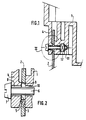
- la figure 1 est une vue en coupe d'un dispositif selon l'invention et
- la figure 2 est une vue agrandie du détail II de la figure 1.
- Les figures montrent le bâti 1 d'un appareil tel qu'un télécopieur, ce bâti portant notamment une carte support 2 d'un détecteur optique constitué par exemple d'une barrette CCD (non représentée).
- Le bâti 1 comporte un corps formant une surface d'appui 3 pour la carte 2 et, réalisée d'une seule pièce avec lui, une languette élastique 4 présentant elle-même une zone d'appui 5 permettant de presser la carte 2 contre la surface d'appui 3 du bâti 1.
- La languette 4 possède une rigidité suffisante dans son plan (parallèle au plan de la carte 2) pour ne posséder aucune liberté de mouvement autre qu'un mouvement de flexion, tel que sa zone d'appui 5 se déplace sensiblement perpendiculairement au plan de la carte 2 et à la surface d'appui 3.
- Une vis 6 possède une tête 7 en appui sur la surface extérieure de la languette 4 et traverse un trou 8 formé dans cette languette et un trou 9 formé dans la carte support 2.
- Le trou 8 possède un diamètre suffisant pour permettre à la vis 6 de tourner librement, et le trou 9 possède un diamètre encore plus grand de manière que, quelle que soit la position de la vis 6 dans le trou 8, elle n'ait aucun contact avec les bords du trou 9 de la plaque 2.
- La vis 6 traverse par ailleurs un trou 10 formé dans le corps du bâti 1 et son extrémité est engagée dans un écrou de serrage 11 possédant une forme en plan carrée et logé dans une rainure de blocage 12 de forme correspondante, permettant d'éviter sa rotation.
- La carte 2 est donc maintenue en appui sur la surface d'appui 3 par un serrage de la vis 6 qui amène la languette élastique 4 à appliquer la carte sur la surface d'appui.
- La vis 6 n'étant pas en contact avec la carte 2, celle-ci ne subit que l'effort de compression perpendiculaire à son plan exercé par la languette 4, lequel effort de compression ne provoque aucun mouvement parasite.
- Une pluralité de dispositifs tels que décrits ci-dessus, disposés en différents endroits de la carte 2, permettent par conséquent de la fixer au bâti. Le réglage de la carte 2 dans son plan est effectué préalablement, après quoi les vis 6 sont serrées sans altérer ce réglage.
Claims (7)
- Procédé de fixation sur le bâti (1) d'un appareil tel qu'un télécopieur, d'une carte support (2) d'un détecteur optique à circuit à transfert de charges, caractérisé par le fait qu'il comprend l'étape consistant à appliquer ladite carte sur une surface d'appui (3) dudit bâti à l'aide d'un organe d'appui (4) mobile sensiblement perpendiculairement au plan de ladite carte et n'ayant pas de liberté de se mouvoir parallèlement à celui-ci.
- Procédé selon la revendication 1, dans lequel l'organe d'appui est déplacé sensiblement perpendiculairement au plan de la carte par actionnement d'un organe de serrage rotatif (6) sans contact avec ladite carte.
- Dispositif de fixation sur le bâti (1) d'un appareil tel qu'un télécopieur, d'une carte support (2) d'un détecteur optique à circuit à transfert de charges, caractérisé par le fait qu'il comprend une surface d'appui (3) formée sur ledit bâti, et un organe d'appui (4) mobile sensiblement perpendiculairement à ladite surface d'appui et n'ayant pas de liberté de se mouvoir parallèlement à celle-ci.
- Dispositif selon la revendication 3, dans lequel ledit organe d'appui comprend une languette élastique réalisée d'une seule pièce avec ledit bâti.
- Dispositif selon l'une quelconque des revendications 3 et 4, comprenant des moyens de serrage rotatifs (6) pour déplacer ledit organe d'appui sensiblement perpendiculairement à ladite surface d'appui.
- Dispositif selon la revendication 5, dans lequel lesdits moyens de serrage rotatifs sont agencés pour traverser ladite carte sans frottement.
- Dispositif selon l'une quelconque des revendications 5 et 6, dans lequel lesdits moyens de serrage rotatifs comprennent une vis traversant ledit organe d'appui et coopérant avec un écrou bloqué en rotation dans un logement formé dans le bâti.
Applications Claiming Priority (2)
| Application Number | Priority Date | Filing Date | Title |
|---|---|---|---|
| FR9303664A FR2703413B1 (fr) | 1993-03-30 | 1993-03-30 | Procédé et dispositif de fixation d'un détecteur optique d'un appareil tel qu'un télécopieur. |
| FR9303664 | 1993-03-30 |
Publications (2)
| Publication Number | Publication Date |
|---|---|
| EP0618761A1 EP0618761A1 (fr) | 1994-10-05 |
| EP0618761B1 true EP0618761B1 (fr) | 1996-12-18 |
Family
ID=9445500
Family Applications (1)
| Application Number | Title | Priority Date | Filing Date |
|---|---|---|---|
| EP94400633A Expired - Lifetime EP0618761B1 (fr) | 1993-03-30 | 1994-03-24 | Procédé et dispositif de fixation d'un détecteur optique d'un appareil tel qu'un télécopieur |
Country Status (6)
| Country | Link |
|---|---|
| EP (1) | EP0618761B1 (fr) |
| DE (1) | DE69401153T2 (fr) |
| DK (1) | DK0618761T3 (fr) |
| ES (1) | ES2097612T3 (fr) |
| FR (1) | FR2703413B1 (fr) |
| GR (1) | GR3022180T3 (fr) |
Families Citing this family (2)
| Publication number | Priority date | Publication date | Assignee | Title |
|---|---|---|---|---|
| DE19517294A1 (de) * | 1995-05-11 | 1996-11-14 | Giesecke & Devrient Gmbh | Vorrichtung zur Prüfung von Blattgut, wie z.B. Banknoten |
| CN103697044A (zh) * | 2013-12-25 | 2014-04-02 | 西安轨道交通装备有限责任公司 | 一种车辆侧面悬挂件的固定结构 |
Family Cites Families (2)
| Publication number | Priority date | Publication date | Assignee | Title |
|---|---|---|---|---|
| US4309856A (en) * | 1980-05-22 | 1982-01-12 | General Motors Corporation | Panel mounting device and assembly |
| US5216525A (en) * | 1990-12-19 | 1993-06-01 | Ncr Corporation | Table top hardware for imaging documents |
-
1993
- 1993-03-30 FR FR9303664A patent/FR2703413B1/fr not_active Expired - Fee Related
-
1994
- 1994-03-24 DK DK94400633.7T patent/DK0618761T3/da active
- 1994-03-24 ES ES94400633T patent/ES2097612T3/es not_active Expired - Lifetime
- 1994-03-24 EP EP94400633A patent/EP0618761B1/fr not_active Expired - Lifetime
- 1994-03-24 DE DE69401153T patent/DE69401153T2/de not_active Expired - Lifetime
-
1996
- 1996-12-30 GR GR960403644T patent/GR3022180T3/el unknown
Also Published As
| Publication number | Publication date |
|---|---|
| EP0618761A1 (fr) | 1994-10-05 |
| ES2097612T3 (es) | 1997-04-01 |
| DK0618761T3 (da) | 1997-06-09 |
| DE69401153D1 (de) | 1997-01-30 |
| FR2703413B1 (fr) | 1995-05-24 |
| DE69401153T2 (de) | 1997-04-17 |
| GR3022180T3 (en) | 1997-03-31 |
| FR2703413A1 (fr) | 1994-10-07 |
Similar Documents
| Publication | Publication Date | Title |
|---|---|---|
| FR2468444A1 (fr) | Cle a bougie a limitateur de couple reglable | |
| EP1497223A1 (fr) | Dispositif de prehension de recipients a commande excentrique | |
| FR2578004A1 (fr) | Verin hydraulique ou pneumatique | |
| EP0618761B1 (fr) | Procédé et dispositif de fixation d'un détecteur optique d'un appareil tel qu'un télécopieur | |
| FR2647555A1 (fr) | Dispositif d'interception de lumiere pour objectif photographique | |
| EP0043785B1 (fr) | Mandrin de fixation d'un outil sur une machine outil | |
| FR2763020A1 (fr) | Dispositif de support pour un rouleau d'un mecanisme d'encrage ou d'un mecanisme de mouillage | |
| FR3111580A3 (fr) | OUTIL DE BRUNISSAGE ASSISTé PAR VIBRATION ULTRASONIQUE POUR TOUR | |
| FR2600004A1 (fr) | Serre-joint d'angle, notamment pour l'assemblage par collage de cadres en bois | |
| EP0337864B1 (fr) | Porte-monture de lunettes perfectionné pour machine à réproduire | |
| WO1998026325A1 (fr) | Dispositif a charniere | |
| EP1252969A1 (fr) | Module à vis anti-choc | |
| FR2654266A1 (fr) | Appareil de commande et/ou de signalisation destine a etre fixe dans une ouverture de tableau. | |
| FR2678538A1 (fr) | Outil de vissage. | |
| FR2653062A1 (fr) | Dispositif pour la deformation elastique d'une plaque d'impression fixee sur un cylindre porte-plaque. | |
| FR2472701A1 (fr) | Dispositif et procede de mise en tension d'un lien de transmission sans fin | |
| EP0618157B1 (fr) | Dispositif de séparation des feuilles dans une machine de bureau et procédé de réglage de la butée de ce dispositif | |
| EP0234171B1 (fr) | Tête d'alésage | |
| FR2677570A1 (fr) | Dispositif de serrage d'un corps par rapport a un referentiel. | |
| FR2698970A1 (fr) | Dispositif pour la fixation de l'objectif d'un appareil tel qu'un télécopieur. | |
| FR2480658A1 (fr) | Dispositif de serrage hydraulique pour machine-outil | |
| EP0521803B1 (fr) | Dispositif de connexion et d'alimentation électrique | |
| BE1005282A0 (fr) | Dispositif de commutation electrique, commandable mecaniquement de facon reglable. | |
| EP1281830A1 (fr) | Charnière, notamment pour panneau pivotant | |
| FR2584766A1 (fr) | Dispositif d'allonge reglable pour gond fixe |
Legal Events
| Date | Code | Title | Description |
|---|---|---|---|
| PUAI | Public reference made under article 153(3) epc to a published international application that has entered the european phase |
Free format text: ORIGINAL CODE: 0009012 |
|
| AK | Designated contracting states |
Kind code of ref document: A1 Designated state(s): BE DE DK ES FR GB GR IE IT LU NL PT |
|
| 17P | Request for examination filed |
Effective date: 19941117 |
|
| 17Q | First examination report despatched |
Effective date: 19950606 |
|
| GRAG | Despatch of communication of intention to grant |
Free format text: ORIGINAL CODE: EPIDOS AGRA |
|
| GRAH | Despatch of communication of intention to grant a patent |
Free format text: ORIGINAL CODE: EPIDOS IGRA |
|
| GRAH | Despatch of communication of intention to grant a patent |
Free format text: ORIGINAL CODE: EPIDOS IGRA |
|
| GRAA | (expected) grant |
Free format text: ORIGINAL CODE: 0009210 |
|
| AK | Designated contracting states |
Kind code of ref document: B1 Designated state(s): BE DE DK ES FR GB GR IE IT LU NL PT |
|
| REF | Corresponds to: |
Ref document number: 69401153 Country of ref document: DE Date of ref document: 19970130 |
|
| REG | Reference to a national code |
Ref country code: IE Ref legal event code: FG4D Free format text: 71097 |
|
| GBT | Gb: translation of ep patent filed (gb section 77(6)(a)/1977) |
Effective date: 19970125 |
|
| ITF | It: translation for a ep patent filed | ||
| REG | Reference to a national code |
Ref country code: GR Ref legal event code: FG4A Free format text: 3022180 |
|
| REG | Reference to a national code |
Ref country code: ES Ref legal event code: FG2A Ref document number: 2097612 Country of ref document: ES Kind code of ref document: T3 |
|
| REG | Reference to a national code |
Ref country code: DK Ref legal event code: T3 |
|
| PLBE | No opposition filed within time limit |
Free format text: ORIGINAL CODE: 0009261 |
|
| STAA | Information on the status of an ep patent application or granted ep patent |
Free format text: STATUS: NO OPPOSITION FILED WITHIN TIME LIMIT |
|
| 26N | No opposition filed | ||
| REG | Reference to a national code |
Ref country code: GB Ref legal event code: IF02 |
|
| PGFP | Annual fee paid to national office [announced via postgrant information from national office to epo] |
Ref country code: IE Payment date: 20050217 Year of fee payment: 12 |
|
| PGFP | Annual fee paid to national office [announced via postgrant information from national office to epo] |
Ref country code: NL Payment date: 20050218 Year of fee payment: 12 |
|
| PGFP | Annual fee paid to national office [announced via postgrant information from national office to epo] |
Ref country code: DK Payment date: 20050223 Year of fee payment: 12 |
|
| PGFP | Annual fee paid to national office [announced via postgrant information from national office to epo] |
Ref country code: GR Payment date: 20050225 Year of fee payment: 12 |
|
| PGFP | Annual fee paid to national office [announced via postgrant information from national office to epo] |
Ref country code: LU Payment date: 20050309 Year of fee payment: 12 |
|
| PGFP | Annual fee paid to national office [announced via postgrant information from national office to epo] |
Ref country code: PT Payment date: 20050316 Year of fee payment: 12 |
|
| PG25 | Lapsed in a contracting state [announced via postgrant information from national office to epo] |
Ref country code: IT Free format text: LAPSE BECAUSE OF NON-PAYMENT OF DUE FEES;WARNING: LAPSES OF ITALIAN PATENTS WITH EFFECTIVE DATE BEFORE 2007 MAY HAVE OCCURRED AT ANY TIME BEFORE 2007. THE CORRECT EFFECTIVE DATE MAY BE DIFFERENT FROM THE ONE RECORDED. Effective date: 20050324 |
|
| PGFP | Annual fee paid to national office [announced via postgrant information from national office to epo] |
Ref country code: BE Payment date: 20050418 Year of fee payment: 12 |
|
| PG25 | Lapsed in a contracting state [announced via postgrant information from national office to epo] |
Ref country code: IE Free format text: LAPSE BECAUSE OF NON-PAYMENT OF DUE FEES Effective date: 20060324 |
|
| PG25 | Lapsed in a contracting state [announced via postgrant information from national office to epo] |
Ref country code: LU Free format text: LAPSE BECAUSE OF NON-PAYMENT OF DUE FEES Effective date: 20060331 Ref country code: DK Free format text: LAPSE BECAUSE OF NON-PAYMENT OF DUE FEES Effective date: 20060331 Ref country code: BE Free format text: LAPSE BECAUSE OF NON-PAYMENT OF DUE FEES Effective date: 20060331 |
|
| REG | Reference to a national code |
Ref country code: FR Ref legal event code: TP Ref country code: FR Ref legal event code: CD Ref country code: FR Ref legal event code: CA |
|
| PG25 | Lapsed in a contracting state [announced via postgrant information from national office to epo] |
Ref country code: PT Free format text: LAPSE BECAUSE OF NON-PAYMENT OF DUE FEES Effective date: 20060925 |
|
| PG25 | Lapsed in a contracting state [announced via postgrant information from national office to epo] |
Ref country code: NL Free format text: LAPSE BECAUSE OF NON-PAYMENT OF DUE FEES Effective date: 20061001 |
|
| REG | Reference to a national code |
Ref country code: DK Ref legal event code: EBP |
|
| REG | Reference to a national code |
Ref country code: PT Ref legal event code: MM4A Free format text: LAPSE DUE TO NON-PAYMENT OF FEES Effective date: 20060925 |
|
| NLV4 | Nl: lapsed or anulled due to non-payment of the annual fee |
Effective date: 20061001 |
|
| REG | Reference to a national code |
Ref country code: IE Ref legal event code: MM4A |
|
| BERE | Be: lapsed |
Owner name: SOC. D'APPLICATIONS GENERALES D'ELECTRICITE ET DE Effective date: 20060331 |
|
| PGRI | Patent reinstated in contracting state [announced from national office to epo] |
Ref country code: IT Effective date: 20080301 |
|
| PG25 | Lapsed in a contracting state [announced via postgrant information from national office to epo] |
Ref country code: GR Free format text: LAPSE BECAUSE OF NON-PAYMENT OF DUE FEES Effective date: 20061002 |
|
| REG | Reference to a national code |
Ref country code: GB Ref legal event code: 732E Free format text: REGISTERED BETWEEN 20090319 AND 20090325 |
|
| REG | Reference to a national code |
Ref country code: GB Ref legal event code: 732E Free format text: REGISTERED BETWEEN 20090326 AND 20090401 |
|
| PGFP | Annual fee paid to national office [announced via postgrant information from national office to epo] |
Ref country code: ES Payment date: 20100309 Year of fee payment: 17 |
|
| PGFP | Annual fee paid to national office [announced via postgrant information from national office to epo] |
Ref country code: IT Payment date: 20100312 Year of fee payment: 17 |
|
| REG | Reference to a national code |
Ref country code: FR Ref legal event code: TP |
|
| REG | Reference to a national code |
Ref country code: FR Ref legal event code: TP Owner name: SAGEMCOM DOCUMENTS SAS, FR Effective date: 20111005 |
|
| REG | Reference to a national code |
Ref document number: 69401153 Ref country code: DE Ref legal event code: R082 Ref document number: 69401153 Country of ref document: DE Representative=s name: , |
|
| REG | Reference to a national code |
Ref country code: DE Ref legal event code: R081 Ref document number: 69401153 Country of ref document: DE Owner name: SAGEMCOM SAS, FR Free format text: FORMER OWNER: SOCIETE D'APPLICATIONS GENERALES D'ELECTRICITE ET DE MECANIQUE SAGEM, PARIS, FR Effective date: 20111228 |
|
| PG25 | Lapsed in a contracting state [announced via postgrant information from national office to epo] |
Ref country code: IT Free format text: LAPSE BECAUSE OF NON-PAYMENT OF DUE FEES Effective date: 20110324 |
|
| REG | Reference to a national code |
Ref country code: ES Ref legal event code: FD2A Effective date: 20120423 |
|
| PG25 | Lapsed in a contracting state [announced via postgrant information from national office to epo] |
Ref country code: ES Free format text: LAPSE BECAUSE OF NON-PAYMENT OF DUE FEES Effective date: 20110325 |
|
| REG | Reference to a national code |
Ref country code: DE Ref legal event code: R081 Ref document number: 69401153 Country of ref document: DE Owner name: SAGEMCOM SAS, FR Free format text: FORMER OWNER: SAGEM TELECOMMUNICATIONS S. A., PARIS, FR Effective date: 20130129 |
|
| PGFP | Annual fee paid to national office [announced via postgrant information from national office to epo] |
Ref country code: GB Payment date: 20130228 Year of fee payment: 20 Ref country code: DE Payment date: 20130221 Year of fee payment: 20 |
|
| PGFP | Annual fee paid to national office [announced via postgrant information from national office to epo] |
Ref country code: FR Payment date: 20130429 Year of fee payment: 20 |
|
| REG | Reference to a national code |
Ref country code: DE Ref legal event code: R071 Ref document number: 69401153 Country of ref document: DE |
|
| REG | Reference to a national code |
Ref country code: GB Ref legal event code: PE20 Expiry date: 20140323 |
|
| PG25 | Lapsed in a contracting state [announced via postgrant information from national office to epo] |
Ref country code: GB Free format text: LAPSE BECAUSE OF EXPIRATION OF PROTECTION Effective date: 20140323 Ref country code: DE Free format text: LAPSE BECAUSE OF EXPIRATION OF PROTECTION Effective date: 20140325 |