EP0619092B1 - Handtuchspender für Rollenhandtücher und Verfahren zu seinem Betrieb - Google Patents
Handtuchspender für Rollenhandtücher und Verfahren zu seinem Betrieb Download PDFInfo
- Publication number
- EP0619092B1 EP0619092B1 EP94103641A EP94103641A EP0619092B1 EP 0619092 B1 EP0619092 B1 EP 0619092B1 EP 94103641 A EP94103641 A EP 94103641A EP 94103641 A EP94103641 A EP 94103641A EP 0619092 B1 EP0619092 B1 EP 0619092B1
- Authority
- EP
- European Patent Office
- Prior art keywords
- towel
- roll
- clean
- dispenser
- towel dispenser
- Prior art date
- Legal status (The legal status is an assumption and is not a legal conclusion. Google has not performed a legal analysis and makes no representation as to the accuracy of the status listed.)
- Expired - Lifetime
Links
Images

Classifications
-
- A—HUMAN NECESSITIES
- A47—FURNITURE; DOMESTIC ARTICLES OR APPLIANCES; COFFEE MILLS; SPICE MILLS; SUCTION CLEANERS IN GENERAL
- A47K—SANITARY EQUIPMENT; ACCESSORIES THEREFOR, e.g. TOILET ACCESSORIES
- A47K10/00—Body-drying implements; Toilet paper; Holders therefor
- A47K10/24—Towel dispensers; Toilet paper dispensers
- A47K10/28—Towel dispensers; Toilet paper dispensers dispensing a clean part and taking-up a soiled part, e.g. using rolls; with dispensers for soap or other detergents; with disinfecting or heating devices
Definitions
- a towel dispenser is known from US-A-3 826 548 become, in which an electric motor for winding the Towel is provided. It can also be rechargeable Battery powered.
- the object of the invention is therefore to a towel apparatus create the advantages of the electric drive and the Control without depending on the mains voltage be.
- the accumulator can selectively all or some of the Functions of the towel dispenser are operated without a direct network connection would be necessary.
- the accumulator can be designed as a commercially available dry accumulator be. But there are also other rechargeable energy stores, e.g. appropriately designed capacitors etc. possible.
- the accumulator can particularly preferably within one Be arranged core of a towel roll. The procedure it is then preferred to operate the towel dispenser as follows:
- a new towel wrap contains in his changing room an accumulator that is in the service mode charged on the occasion of washing and possibly on his Function was checked.
- This clean wrap is in one Clean towel holder of the towel dispenser used, after the winding core of the previous Sauber towel wrap taken from the clean towel holder and then in a used towel holder was used, from which now in turn, a used towel wrap was removed. This will now be used to wash and recharge the battery returned, so that an automatic cycle with Recharging the battery results.
- the accumulator can preferably be within a winding core a towel roll may be arranged, this preferably an inner core to be attached in the towel dispenser in a rotationally fixed manner and rotatably mounted on it a winding tube for the towel wrap contains.
- contacting means for connecting the Accumulator on the drive and / or control means of the towel dispenser and / or charging means are provided on the winding core, preferably with a clean towel rail and / or a used towel rail are trained. It can therefore be provided that only the Accumulator contained in the clean towel wrap on the towel dispenser is electrically connected; however, it is also possible, this with clean and / or used towel wraps to provide.
- a towel roll drive can preferably also be provided in the winding core with an electric motor and possibly a gear be provided, which can drive the winding tube directly. In this case, only control connections would be left outside, which may also be provided contactless can.
- the control means for example one Control electronics can be provided in the winding core.
- the procedure for washing the towel can vary be carried out. For example, you can put the towel over one not used as a towel and therefore not to be washed leader, for example from a film or coated fabric, connect with a winding core. When washing, the winding core could then be outside of the actual one Washing process remain partially during the opening credits also protrudes into the washing liquid. After this Washing can then immediately again on the winding core be wound up. But it is also possible to use the towels directly connected to each other to make them long, to run practically endless web through the washing apparatus. This can be done in a conventional manner by stapling and Subsequent reopening is done after the towel is unwound from the winding core.
- connection means can be provided with which on the one hand the towels together and on the other hand on the winding core can be attached, for example hooks, zipper-like Lanyards, adhesive connectors, like them e.g. are known as Velcro, or the like.
- the invention proposes that the roll towel in a cassette-like, interchangeable, usable in the towel dispenser and / or attachable to this Exchange unit is provided which receives the accumulator.
- This unit or Cassette can wrap a clean towel and a used towel included and preferably from a cassette case be surrounded, the at least one inlet / outlet opening for a towel loop.
- Such an exchange unit or cassette so preferably largely completed, but also from one open frame with bearings for the individual wraps could exist, so it is possible with a handle and carry out the exchange without particularly threading the towel.
- Functional elements can already be in the cassette be installed, for example guide rollers, however also the drive of the winding and Control means. So it could be act as a largely functional unit that practically only on a wall bracket with a quick connection needs to be attached to be ready for immediate use to be. This unity would also have the advantage that it can be built very small and light.
- the size is practically only by the roll width on the one hand and determined by the winding diameter on the other hand, wherein because of the precise guidance of the towel wrap the dimension in the plane of both winding axes not the sum of the two needs to correspond to the maximum angular diameter since this can overlap if it is ensured that the Wrap in their half unwound or wound position can run freely from each other.
- the end feed be accomplished electrically, for example by a separate feed motor drives a pair of feed rollers, that draws the end.
- a separate feed motor drives a pair of feed rollers, that draws the end.
- the towel is on the the front of the towel dispenser facing the user subtracted below and runs on the one removed by the user Side of the loop forming again in the towel dispenser on. This corresponds to the natural operating sequence, if mechanical actuation is necessary.
- the threading a new towel is with this Difficult to run, especially if the towel is a Row of guide and locking rollers, etc. must go through.
- the Threading is by partially opening insertion gaps etc. have been simplified when opening the dispenser housing, however, further simplification would be desirable.
- This system is also not hygienic optimal.
- the user always pulls a clean front Towel section out, but at the back of the loop there is mostly used towel, so that it Hanging drying comes into contact with it almost automatically.
- Towel loop runs in the opposite direction, namely that clean towel on the back of the loop, far from the user emerges and the used track at the front into the Device is running in. So there is the one you are currently using Towel section always seen at the end in the transport direction the freely accessible loop and can be used in an automatic Move in immediately after use, if necessary with a Time delay, drawn into the towel dispenser and the same can also be rolled up on the used towel wrap. At this also exists when the loop is hanging freely always out of a clean towel because of the transport mechanism a clean towel length corresponding to the draw-in length spent.
- Changing the towel rolls can also be done with conventional ones Towel running direction (front down) be simplified, if the clean towel wrap over the used wrap is used. This can also be for other reasons, e.g. due to the simplified compliance with hygiene regulations, be beneficial.
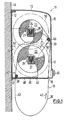
- Fig. 1 shows a towel dispenser 11, one on a wall 14 attached base plate 12 and a hinged housing 13 has, which surrounds an interior 15 and an inlet opening 16 and an outlet opening 17 for a towel 18 having.
- the base plate 12 belongs to a support frame 19 with two Sidewalls 20, between which two towel rolls 21 are stored. In the present case is under a clean towel wrap 22 and above a used towel wrap 23 intended.
- the towel 18 is wound on winding cores 24 (FIG. 2). They have an inner core 25 which has connection elements 26 can be used in corresponding holders 27 on the towel dispenser are. These recordings 27 are on the side walls 20 of the base part 19 attached and have one on both Connection elements 26 provided on the sides of the inner core 25 customized shape. They are designed so that they have the inner core Non-rotating, but removable, hold in the recordings. In this and the connection elements are electrical contacting means 28 provided, i.e. interacting contact tracks. It it is possible to have one pole of the contacting means to provide a recording and in any case it is advantageous the connection elements 26 and receptacle 27 on both To design sides of the winding core differently, so that the wrap is certainly used in a certain position becomes.
- the different contacts can only be in the area a connecting element or be provided on both. With united them or in addition, snap-locking elements be provided, the clear engagement of the Ensures winding core in his recordings.
- the inner core 25 contains the entire in the embodiment Drive and the energy storage for the winding drive.
- the tubular inner core 25 are axially one behind the other Accumulator 29, control electronics 30, an electric motor 31 and an associated gear 32 arranged, for example via a pinion 33 on an internal toothing Winding sleeve 34 acts by means of bearings 35 on the inner core is rotatably mounted.
- seals 36 can the inner core is shielded from the outside against all environmental influences be, the functional parts in it only about the connecting elements 26 can be influenced electrically. It is but it is also possible to hermetically seal off the individual units and only one drive element, for example that Lead out pinion 33, sealed.
- connection means 37 On the winding tube 34 and at the inner end of the towel wrap 21 cooperating connection means 37 are provided, for example hooks and eyes, interacting adhesive elements, Zipper-like connections or the like to a towel end to hold onto the winding tube for winding.
- the connection means provided on the towel should preferably be used be designed so that they are as direct or if necessary, can also be connected to one another via a middle piece.
- the winding sleeve and that on the winding outer end of the towel the softer, textile loops have part of a textile adhesive fastener, while the inside of the towel wraps the one with the corresponding one Hook structures provided part of this adhesive or Has Velcro.
- Fig. 1 it can be seen that the clean winding 22 in lower part of the towel dispenser 11 is arranged and that Towel on its rear part closer to wall 14 is led below, runs there via a guide 38, outside of the housing 13 forms a loop 39 and through the Opening 16 in the front housing part runs into this again, to a guide 40 on the in the upper part of the housing stored used towel roll 23 wound up become.
- the used towel section 41 runs Wrap from the user side.
- the loop gets that is, always when actuated in the direction of towel travel 42 a clean towel section 43 on the remote user Back of the loop 39 fed during the use section 44 on the user side, but shortly before Entry of the loop into the opening 16 is.
- the housing hood 13 can be pivoted so that it all outer towel parts exposed, except for a floor section 45, which contains the exit gap 17 and the entry gap 16 limited on one side.
- This switching electronics can be attached to the towel dispenser instead of in the winding core or it could be, for example, the electronics on the dispenser and the components that switch the motor current (mechanical or electronic relays) can be provided in the winding core.
- the towel dispenser enables the following when used Method:
- the towel dispenser 11 can be installed in any position Place a wall attached without having an electrical Connection needed. After attaching the housing, which has the shape of a hood around the axis 47 downwards pivoted. A clean towel wrap 22 is placed in the receptacles 27 used. The free towel end hangs in the Area of the base plate 12 down and practically falls off out of the exit gap 17 alone, can be gripped there and, without it again through a slot or a roll nip needs to be put forward and be pulled up. In the upper receptacle 27, an empty one Winding core 24 inserted and the free towel end on this attached by means of the connection means 37. The towel 18 runs over the guide 40.
- the loop 39 spent. This can be done either by rotating the clean wrap 22 in the direction of actuation and / or by rotating the Used winding 23 against the direction of actuation 42 respectively. This becomes a timing element in the switching electronics 30 started, which has a term that is certain is longer than the usual drying process. After the User at the use section 44 of the loop 39 has dried the hands, this time delay sets the transport starts again and pulls the loop 39 on. Either the clean section 43 can be rotated of the clean wrap against the towel transport direction 42 be fed so that the used section then as Section 48 lies under the housing and is lighter there can dry. However, it is also possible to use this section immediately by turning the used reel 23 in Actuating direction 42 into the housing and only the clean rest of the remaining loop 39 by turning back the Pull in the clean wrap.
- the accumulator 29 was in the towel washing in to the service company after having previously been to the Regeneration has been completely discharged. In addition, could there test procedures for the accumulator, the motor and the Circuit be made so that the functionality the winding is always ensured.
- the still functional Accumulator directly actuates the used reel Bring so that only control currents via the connections 26 are to be managed, while the entire high-voltage drive in Remains inside the wrap. This makes contacting easier via the contacting means 28 considerably if necessary, can also be carried out without contact.
- control means and thus the switching electronics are attached to the towel dispenser outside the wraps, so be, especially if the high-current switching relay are provided outside, also high-voltage connections from the Wrapping led outwards.
- the each freshly charged battery 29 in the clean wrap also ensure the drive of the used reel 23, so that the accumulator in the used winding 23 is no longer charged must be to ensure the function.
- the invention makes it possible to use a minimum of external guides, without towel drive in nips etc. and avoiding larger mechanical ones
- All functions can be carried out by direct winding actuation.
- the Inserting and changing the wrap is particularly easy and can be flawless even by inexperienced people without much thought be made.
- every towel wrap ensures the function even if the towel drive, for example, does not have Winding core drive, but via other drive means, For example, external rollers are made.
- the towel dispenser with smaller External dimensions can be produced than previous ones. Since there are no mechanical control or drive components in addition to the Windings must run, these determine the width.
- the Depth is determined by the winding diameter and the height can even be chosen less than the sum of the two maximum winding diameter, because never two full windings in the Towel dispensers are available. So it just has to take care of it be determined by two half-unwrapped wrap Overall dimensions are observed.
- the maximum winding diameter 50 (dash-dotted in FIG. 1) can therefore overlap.
- a flexible separation, such as a film 51 may be provided.
- Fig. 3 shows a towel dispenser 11, which consists of a wall bracket 12a and a cassette 60, in which a clean towel wrap 22 and a used towel wrap 23 and all drive and control means and an accumulator 29 are provided.
- the drive and control functions can be the same as previously described.
- This cassette 60 will be exchanged for one after the supply of clean towels other cassette replaced by the service mode Washing the towel and recharging the battery etc. is put back into the ready-to-use condition. Except such an embodiment in which the cassette 60 all Functional parts of the towel dispenser included and only attached to a wall bracket with a quick release becomes, numerous other cassette designs are possible.
- a cassette can be used only contains the towel rolls and the accumulator 29 and over contacting means provided on the cassette to the drive electronics connected in the towel dispenser is provided.
- the towel wraps operated via mechanical clutches, for example through gears or dog clutches with automatic resilient snap-in elements.
- Such a cassette can then be used the towel apparatus are inserted and sometimes also Include housing sections of the towel dispenser. In each The trap becomes an easy to replace unit created with appropriate training to the outside while storage and transport is hygienically complete.
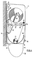
- Fig. 4 shows schematically a towel dispenser according to the invention with a conventional one Drive by manual pull on the towel.
- the one below loop 39 hanging out of the device runs in it Case in the opposite direction to previous devices, i.e. the use section 44 of the towel is on the User-facing side of the towel dispenser during that used towel near the back of the towel dispenser enters the housing again.
- the clean towel wrap 22 is designed without a winding core, so that the wrap lies freely in a tub 55. From there the towel runs between a ratchet wheel 56 and one Pinch roller 57 through and on the front of the device down to loop 39.
- the used towel section 41 runs in at the back of the device from below and passes a nip between two rollers 58, one of which is connected to an electric motor 59. This stands electrically connected to a control device 66 as well with an electric accumulator 29.
- the arrangement of the accumulator is in the towel dispenser according to FIG. 4 in a manner not according to the invention.
- the ratchet wheel 56 drives a winding roller 61 on which the Used towel wrap 23 rests with its circumference. This is wound on an inactive winding core 62, which can run diagonally upwards in a guide 63, so that by rotating the take-up roller 61 identically the same Amount of towel is wound up, as by pulling on the towel is deducted from the clean towel wrap 22.
- the signal generated thereby sets via the control device, powered by the accumulator 29, the motor 59 active in operation, in the feed direction, so that after passing through the contacts 64 freely fallen down Is completely drawn in at the end. Since the used winding 23 was not driven, but only the pair of rollers 58 this end stored in a pocket 67. When removing the Used windings are withdrawn from it and can by hand around the used reel.
- the controller also has a timer that keeps the motor 59 in operation until it is ensured is that the end is completely drawn.
- Dependent on This function can trigger other functions, whose trigger signal is the consumption of the clean wrap, for example, unblocking another Towel dispenser loaded with a clean towel and was locked as long as the other was still in use was the forwarding of the signal to a control center or the like ..
- the signal can be passed on by cable or wirelessly become.
Landscapes
- Health & Medical Sciences (AREA)
- Public Health (AREA)
- Body Washing Hand Wipes And Brushes (AREA)
- Sanitary Thin Papers (AREA)
Description
- Fig. 1
- eine schematische, teilgeschnittene Seitenansicht eines Handtuchspenders,
- Fig. 2
- einen schematischen Längsschnitt durch einen Wickelkern,
- Fig. 3
- einen Schnitt entsprechend Fig. 1 durch einen Handtuchspender mit einer Austausch-Einheit (Kassette für die Rollenhandtücher),
- Fig. 4
- eine Darstellung eines nicht erfindungsgemäßen Handtuchspenders mit mechanischem Antrieb und elektrischem Handtuchenden-Einzug.
Claims (16)
- Handtuchspender (11) für Rollenhandtücher (18), mit elektrischem Antrieb für wenigstens eine Handtuchspenderfunktion, mit einem in den Handtuchspender (11) eingesetzten aufladbaren elektrischen Akkumulator (29), dadurch gekennzeichnet, daß der Akkumulator (29) derart einem Handtuchwickel (21) zugeordnet ist, daß er beim Auswechseln des Handtuchwickels (21) stets zu seiner Wiederaufladung zusammen mit dem Handtuchwickel (21) entnehmbar und zusammen mit diesem wieder einsetzbar ist.
- Handtuchspender nach Anspruch 1, dadurch gekennzeichnet, daß der Akkumulator (29) innerhalb eines Wickelkerns (24) eines Handtuchwickels (21) angeordnet ist.
- Handtuchspender nach Anspruch 1 oder 2, dadurch gekennzeichnet, daß Kontaktierungsmittel (28) zum Anschluß des Akkumulators (29) an Antriebs- und/oder Steuermittel und/oder Auflademittel an dem Wickelkern (24) vorgesehen sind, die vorzugsweise mit einer Sauber-Handtuch-Aufnahme und/oder einer Gebraucht-Handtuch-Aufnahme (27) zusammenwirkend ausgebildet sind.
- Handtuchspender nach Anspruch 2 oder 3, dadurch gekennzeichnet, daß der Wickelkern (24) einen im Handtuchspender (11) drehfest anzubringenden Innenkern (25) und, darauf drehbar gelagert, eine Wickelhülse (34) für den Handtuchwickel (21) enthält.
- Handtuchspender nach einem der Ansprüche 2 bis 4, dadurch gekennzeichnet, daß im Wickelkern (24) ein Handtuchrollenantrieb mit einem Elektromotor (31) sowie ggf. ein Getriebe (32) vorgesehen sind, die vorzugsweise eine Wickelhülse (34) direkt antreiben.
- Handtuchspender nach einem der vorhergehenden Ansprüche, dadurch gekennzeichnet, daß das Handtuch (18) über einen nicht als Handtuch eingesetzten und nicht zu waschenden Vorspann mit wenigstens einem Wickelkern (24) verbindbar ist.
- Handtuchspender nach einem der vorhergehenden Ansprüche, dadurch gekennzeichnet, daß das Handtuch (18) Anschlußmittel (37) für seine Verbindung mit dem Wickelkern (24) und/oder mit einem anderen Handtuch (18) aufweist.
- Handtuchspender nach einem der vorhergehenden Ansprüche, dadurch gekennzeichnet, daß das Rollenhandtuch (18) in einer kassettenartigen, austauschbaren, in den Handtuchspender (11) einsetzbaren und/oder an diesen ansetzbaren Austauscheinheit (60) vorgesehen ist, die den Akkumulator (29) aufnimmt.
- Handtuchspender nach Anspruch 8, dadurch gekennzeichnet, daß die Austauscheinheit (60) je einen Kern für einen Sauber-Handtuch- und einen Gebraucht-Handtuch-Wickel (22, 23) enthält, die vorzugsweise von einem Kassettengehäuse umgeben sind, das wenigstens eine Ein/Auslaßöffnung für eine Handtuchschlaufe (39) aufweist.
- Handtuchspender nach einem der Ansprüche 8 oder 9, dadurch gekennzeichnet, daß die Austauscheinheit (60) Antriebs-, Führungs- und/oder Steuermittel für die Spenderfunktion enthält, vorzugsweise für alle Handtuchspenderfunktionen, und insbesondere an einer Halterung (12a) mit einem Schnellverschluß anbringbar ist.
- Handtuchspender nach einem der Ansprüche 8 oder 9, dadurch gekennzeichnet, daß in der Austauscheinheit (60) eine Auf- und Abwickelrolle für einen Sauber- und Gebraucht-Handtuch-Wickel (22, 23) vorgesehen sind, die mit derartigem Abstand voneinander angeordnet sind, daß sich die maximalen Wickeldurchmesser (50) des Handtuchs (18) auf ihnen gegenseitig überlappen.
- Handtuchspender nach einem der vorhergehenden Ansprüche, dadurch gekennzeichnet, daß der Handtuchtransport manuell betätigbar ist und mit einem elektrischen Endeneinzug nach Verbrauch des Sauber-Handtuch-Vorrates versehen ist, wobei ein Generator, der ggf. durch einen Antriebsmotor (31) des Endeneinzugs gebildet ist, zur Aufladung des Akkumulators (29) ausgebildet und angeschlossen ist.
- Handtuchspender nach einem der vorhergehenden Ansprüche, dadurch gekennzeichnet, daß der Akkumulator (29) als entsprechend dimensionierter Kondensator ausgebildet ist.
- Handtuchspender nach Anspruch 1, dadurch gekennzeichnet, daß die Antriebs-, Steuerungs- und Führungsmittel für das Handtuch (18) derart ausgebildet sind, daß das Handtuch (18) eine Handtuchschlaufe (39) bildet, die an der benutzerfernen Seite aus dem Handtuchspender mit Sauber-Handtuch versorgt wird und an der dem Benutzer zugewandten Seite durch Einzug von Gebraucht-Handtuch in den Handtuchspender (11) einläuft, wobei der Antrieb (31, 32) die Handtuchschlaufe (39) nach einer Benutzung so weit einzieht, daß der benutzte Handtuchabschnitt (41) unter einer Gehäuseabdeckung liegt.
- Handtuchspender nach Anspruch 14, dadurch gekennzeichnet, daß zusätzlich eine Schlaufeneinzugsvorrichtung vorgesehen ist, die die Schlaufe (39) nach der Benutzung an den Handtuchspender (11) heranzieht, und zwar durch Einziehen eines Schlaufenteils auf der Seite des sauberen Handtuchs (18).
- Verfahren zum Betrieb eines Handtuchspenders (11) nach einem der vorhergehenden Ansprüche, dadurch gekennzeichnet, daß ein einen Wickelkern (24) eines Handtuchwickels (21) enthaltender, mit einem anläßlich des Waschens des Handtuchs (18) aufgeladenen und ggf. geprüften Akkumulators (29) in eine Sauber-Handtuchaufnahme (27) des Handtuchspenders (11) eingesetzt wird, nachdem der Wickelkern (24) des vorherigen Sauber-Handtuch-Wickels aus der Sauber-Handtuchaufnahme entnommen und in eine Gebraucht-Handtuchaufnahme (27) eingesetzt wurde, aus der ein Gebraucht-Handtuch-Wickel (23) entnommen wurde, der zum Waschen und zum Aufladen des Akkumulators (29) zurückgegeben wird.
Applications Claiming Priority (2)
| Application Number | Priority Date | Filing Date | Title |
|---|---|---|---|
| DE4310716 | 1993-04-01 | ||
| DE4310716A DE4310716A1 (de) | 1993-04-01 | 1993-04-01 | Handtuchspender für Rollenhandtücher |
Publications (3)
| Publication Number | Publication Date |
|---|---|
| EP0619092A2 EP0619092A2 (de) | 1994-10-12 |
| EP0619092A3 EP0619092A3 (de) | 1995-01-04 |
| EP0619092B1 true EP0619092B1 (de) | 1999-08-04 |
Family
ID=6484485
Family Applications (1)
| Application Number | Title | Priority Date | Filing Date |
|---|---|---|---|
| EP94103641A Expired - Lifetime EP0619092B1 (de) | 1993-04-01 | 1994-03-10 | Handtuchspender für Rollenhandtücher und Verfahren zu seinem Betrieb |
Country Status (3)
| Country | Link |
|---|---|
| EP (1) | EP0619092B1 (de) |
| AT (1) | ATE182763T1 (de) |
| DE (2) | DE4310716A1 (de) |
Cited By (1)
| Publication number | Priority date | Publication date | Assignee | Title |
|---|---|---|---|---|
| CN107769314A (zh) * | 2012-12-11 | 2018-03-06 | 斯马特浪潮科技公司 | 用于分发器的功率管理系统 |
Families Citing this family (5)
| Publication number | Priority date | Publication date | Assignee | Title |
|---|---|---|---|---|
| NL1034148C2 (nl) * | 2007-07-17 | 2009-01-20 | Vendor Bv | Handdoekmateriaal met hechtelementen. |
| CH709343A1 (de) * | 2014-03-07 | 2015-09-15 | Urs Zahnd | Hygienischer Griff. |
| DE102020116995B4 (de) | 2020-06-29 | 2024-07-25 | Ille Papier-Service Gmbh | Handtuchspender |
| CN116421087A (zh) * | 2023-04-21 | 2023-07-14 | 燕山大学 | 一种公共卫生间取布器 |
| US11937740B1 (en) | 2023-05-02 | 2024-03-26 | Wei Huang | Fabric towel dispenser with towel replacement arrangement |
Family Cites Families (7)
| Publication number | Priority date | Publication date | Assignee | Title |
|---|---|---|---|---|
| CH528256A (de) * | 1972-01-28 | 1972-09-30 | Cws Int Ag | Handtuchbahnausgeber |
| US3826548A (en) * | 1972-02-04 | 1974-07-30 | Nemco Apparatebau Ag | Dispenser for hand towelling |
| GB8300477D0 (en) * | 1983-01-08 | 1983-02-09 | Glynwed Screws & Fastenings Lt | Dispensing apparatus |
| GB2141401B (en) * | 1983-06-15 | 1986-10-15 | Bowater Scott Corp | Sheet material dispenser |
| DE3432694A1 (de) * | 1984-09-06 | 1986-03-13 | Erich Schumm Gmbh, 7157 Murrhardt | Handtuch-spender |
| GB8709510D0 (en) * | 1987-04-22 | 1987-05-28 | Kennedy Engineers Holdings Ltd | Continuous towel cabinets |
| DE3843851A1 (de) * | 1988-12-24 | 1990-06-28 | Schumm Erich Kg | Handtuchspender |
-
1993
- 1993-04-01 DE DE4310716A patent/DE4310716A1/de not_active Withdrawn
-
1994
- 1994-03-10 DE DE59408559T patent/DE59408559D1/de not_active Expired - Fee Related
- 1994-03-10 AT AT94103641T patent/ATE182763T1/de not_active IP Right Cessation
- 1994-03-10 EP EP94103641A patent/EP0619092B1/de not_active Expired - Lifetime
Cited By (2)
| Publication number | Priority date | Publication date | Assignee | Title |
|---|---|---|---|---|
| CN107769314A (zh) * | 2012-12-11 | 2018-03-06 | 斯马特浪潮科技公司 | 用于分发器的功率管理系统 |
| CN107769314B (zh) * | 2012-12-11 | 2020-12-01 | 斯马特浪潮科技股份有限公司 | 用于分发器的功率管理系统 |
Also Published As
| Publication number | Publication date |
|---|---|
| ATE182763T1 (de) | 1999-08-15 |
| DE4310716A1 (de) | 1994-10-06 |
| EP0619092A2 (de) | 1994-10-12 |
| EP0619092A3 (de) | 1995-01-04 |
| DE59408559D1 (de) | 1999-09-09 |
Similar Documents
| Publication | Publication Date | Title |
|---|---|---|
| EP0821561B1 (de) | Einfädelung von flächigem bandmaterial in einem handtuchspender | |
| DE60207444T2 (de) | Elektrischer spender für aufgerolltes produkt | |
| DE69203341T2 (de) | Stoffhandtuchspender. | |
| DE60028043T2 (de) | Elektronisch gesteuerter spender für aufgerollte handtücher | |
| DE2121426A1 (de) | Verfahren und Vorrichtung zum Abnehmen aufgespulter Wickel und Aufsetzen leerer Wickelkerne | |
| DE3743083C2 (de) | Handstaubsauger | |
| CH672409A5 (de) | ||
| WO2002015763A1 (de) | Spender für reinigungstüchlein | |
| DE4310716A1 (de) | Handtuchspender für Rollenhandtücher | |
| DE60109091T2 (de) | Aufladevorrichtung für Wischmaterialspender | |
| DE19840831A1 (de) | Tragbare Aufrollanordnung mit Eigenantrieb, insbesondere für Kabel und Schläuche | |
| DE3233543A1 (de) | Vorrichtung zum gefalteten aufwickeln eines feuerwehrschlauches | |
| DE2606458A1 (de) | Kopiergeraet | |
| DE20300805U1 (de) | Vorrichtung zur Halterung von Leitungen | |
| EP0376152B1 (de) | Handtuchspender | |
| EP1191872B1 (de) | Handtuchspender | |
| DE69209064T2 (de) | Automatischer Spender für von einer kontinuierlichen Rolle abtrennbare Papierhandtücher | |
| DE20309309U1 (de) | Handtuchspender für Rollen-Handtücher | |
| EP0173978B1 (de) | Handtuch-Spender | |
| EP0334315A1 (de) | Toilettensitz | |
| EP0150783A2 (de) | Verfahren, Vorrichtung und Spulenkörpern zum Aufwickeln von Formbändern | |
| DE69606540T2 (de) | Handtuchspender | |
| WO1993005695A1 (de) | Toilettensitz | |
| CH531340A (de) | Handtuchbahnausgeber | |
| DE3743082A1 (de) | Handstaubsauger, insbesondere kleinstaubsauger |
Legal Events
| Date | Code | Title | Description |
|---|---|---|---|
| PUAI | Public reference made under article 153(3) epc to a published international application that has entered the european phase |
Free format text: ORIGINAL CODE: 0009012 |
|
| AK | Designated contracting states |
Kind code of ref document: A2 Designated state(s): AT BE CH DE DK ES FR GB GR IE IT LI LU MC NL PT SE |
|
| PUAL | Search report despatched |
Free format text: ORIGINAL CODE: 0009013 |
|
| AK | Designated contracting states |
Kind code of ref document: A3 Designated state(s): AT BE CH DE DK ES FR GB GR IE IT LI LU MC NL PT SE |
|
| 17P | Request for examination filed |
Effective date: 19950413 |
|
| 17Q | First examination report despatched |
Effective date: 19970325 |
|
| GRAG | Despatch of communication of intention to grant |
Free format text: ORIGINAL CODE: EPIDOS AGRA |
|
| RAP1 | Party data changed (applicant data changed or rights of an application transferred) |
Owner name: ERICH SCHUMM GMBH |
|
| GRAG | Despatch of communication of intention to grant |
Free format text: ORIGINAL CODE: EPIDOS AGRA |
|
| GRAH | Despatch of communication of intention to grant a patent |
Free format text: ORIGINAL CODE: EPIDOS IGRA |
|
| GRAH | Despatch of communication of intention to grant a patent |
Free format text: ORIGINAL CODE: EPIDOS IGRA |
|
| GRAA | (expected) grant |
Free format text: ORIGINAL CODE: 0009210 |
|
| AK | Designated contracting states |
Kind code of ref document: B1 Designated state(s): AT BE CH DE DK ES FR GB GR IE IT LI LU MC NL PT SE |
|
| PG25 | Lapsed in a contracting state [announced via postgrant information from national office to epo] |
Ref country code: SE Free format text: THE PATENT HAS BEEN ANNULLED BY A DECISION OF A NATIONAL AUTHORITY Effective date: 19990804 Ref country code: NL Free format text: LAPSE BECAUSE OF FAILURE TO SUBMIT A TRANSLATION OF THE DESCRIPTION OR TO PAY THE FEE WITHIN THE PRESCRIBED TIME-LIMIT Effective date: 19990804 Ref country code: GR Free format text: LAPSE BECAUSE OF NON-PAYMENT OF DUE FEES Effective date: 19990804 Ref country code: ES Free format text: THE PATENT HAS BEEN ANNULLED BY A DECISION OF A NATIONAL AUTHORITY Effective date: 19990804 |
|
| REF | Corresponds to: |
Ref document number: 182763 Country of ref document: AT Date of ref document: 19990815 Kind code of ref document: T |
|
| REG | Reference to a national code |
Ref country code: CH Ref legal event code: EP |
|
| REF | Corresponds to: |
Ref document number: 59408559 Country of ref document: DE Date of ref document: 19990909 |
|
| REG | Reference to a national code |
Ref country code: IE Ref legal event code: FG4D Free format text: GERMAN |
|
| ET | Fr: translation filed | ||
| ITF | It: translation for a ep patent filed | ||
| PG25 | Lapsed in a contracting state [announced via postgrant information from national office to epo] |
Ref country code: PT Free format text: LAPSE BECAUSE OF FAILURE TO SUBMIT A TRANSLATION OF THE DESCRIPTION OR TO PAY THE FEE WITHIN THE PRESCRIBED TIME-LIMIT Effective date: 19991104 Ref country code: DK Free format text: LAPSE BECAUSE OF FAILURE TO SUBMIT A TRANSLATION OF THE DESCRIPTION OR TO PAY THE FEE WITHIN THE PRESCRIBED TIME-LIMIT Effective date: 19991104 |
|
| GBT | Gb: translation of ep patent filed (gb section 77(6)(a)/1977) |
Effective date: 19991018 |
|
| NLV1 | Nl: lapsed or annulled due to failure to fulfill the requirements of art. 29p and 29m of the patents act | ||
| PGFP | Annual fee paid to national office [announced via postgrant information from national office to epo] |
Ref country code: GB Payment date: 20000224 Year of fee payment: 7 |
|
| PG25 | Lapsed in a contracting state [announced via postgrant information from national office to epo] |
Ref country code: LU Free format text: LAPSE BECAUSE OF NON-PAYMENT OF DUE FEES Effective date: 20000310 Ref country code: AT Free format text: LAPSE BECAUSE OF NON-PAYMENT OF DUE FEES Effective date: 20000310 |
|
| PGFP | Annual fee paid to national office [announced via postgrant information from national office to epo] |
Ref country code: FR Payment date: 20000320 Year of fee payment: 7 |
|
| PG25 | Lapsed in a contracting state [announced via postgrant information from national office to epo] |
Ref country code: LI Free format text: LAPSE BECAUSE OF NON-PAYMENT OF DUE FEES Effective date: 20000331 Ref country code: CH Free format text: LAPSE BECAUSE OF NON-PAYMENT OF DUE FEES Effective date: 20000331 Ref country code: BE Free format text: LAPSE BECAUSE OF NON-PAYMENT OF DUE FEES Effective date: 20000331 |
|
| PLBE | No opposition filed within time limit |
Free format text: ORIGINAL CODE: 0009261 |
|
| STAA | Information on the status of an ep patent application or granted ep patent |
Free format text: STATUS: NO OPPOSITION FILED WITHIN TIME LIMIT |
|
| 26N | No opposition filed | ||
| PG25 | Lapsed in a contracting state [announced via postgrant information from national office to epo] |
Ref country code: IE Free format text: LAPSE BECAUSE OF NON-PAYMENT OF DUE FEES Effective date: 20000719 |
|
| REG | Reference to a national code |
Ref country code: IE Ref legal event code: FD4D |
|
| BERE | Be: lapsed |
Owner name: ERICH SCHUMM G.M.B.H. Effective date: 20000331 |
|
| PG25 | Lapsed in a contracting state [announced via postgrant information from national office to epo] |
Ref country code: MC Free format text: LAPSE BECAUSE OF NON-PAYMENT OF DUE FEES Effective date: 20000930 |
|
| REG | Reference to a national code |
Ref country code: CH Ref legal event code: PL |
|
| PG25 | Lapsed in a contracting state [announced via postgrant information from national office to epo] |
Ref country code: GB Free format text: LAPSE BECAUSE OF NON-PAYMENT OF DUE FEES Effective date: 20010310 |
|
| GBPC | Gb: european patent ceased through non-payment of renewal fee |
Effective date: 20010310 |
|
| PG25 | Lapsed in a contracting state [announced via postgrant information from national office to epo] |
Ref country code: FR Free format text: LAPSE BECAUSE OF NON-PAYMENT OF DUE FEES Effective date: 20011130 |
|
| REG | Reference to a national code |
Ref country code: FR Ref legal event code: ST |
|
| PGFP | Annual fee paid to national office [announced via postgrant information from national office to epo] |
Ref country code: DE Payment date: 20040417 Year of fee payment: 11 |
|
| PG25 | Lapsed in a contracting state [announced via postgrant information from national office to epo] |
Ref country code: IT Free format text: LAPSE BECAUSE OF NON-PAYMENT OF DUE FEES;WARNING: LAPSES OF ITALIAN PATENTS WITH EFFECTIVE DATE BEFORE 2007 MAY HAVE OCCURRED AT ANY TIME BEFORE 2007. THE CORRECT EFFECTIVE DATE MAY BE DIFFERENT FROM THE ONE RECORDED. Effective date: 20050310 |
|
| PG25 | Lapsed in a contracting state [announced via postgrant information from national office to epo] |
Ref country code: DE Free format text: LAPSE BECAUSE OF NON-PAYMENT OF DUE FEES Effective date: 20051001 |