EP0619123A2 - Stimulateur électrique de régénération des nerfs - Google Patents
Stimulateur électrique de régénération des nerfs Download PDFInfo
- Publication number
- EP0619123A2 EP0619123A2 EP94400761A EP94400761A EP0619123A2 EP 0619123 A2 EP0619123 A2 EP 0619123A2 EP 94400761 A EP94400761 A EP 94400761A EP 94400761 A EP94400761 A EP 94400761A EP 0619123 A2 EP0619123 A2 EP 0619123A2
- Authority
- EP
- European Patent Office
- Prior art keywords
- antenna coil
- control processor
- stimulator
- external controller
- signal
- Prior art date
- Legal status (The legal status is an assumption and is not a legal conclusion. Google has not performed a legal analysis and makes no representation as to the accuracy of the status listed.)
- Withdrawn
Links
- 230000001172 regenerating effect Effects 0.000 title abstract description 5
- 230000000638 stimulation Effects 0.000 claims abstract description 13
- 210000000944 nerve tissue Anatomy 0.000 claims abstract description 7
- 230000008929 regeneration Effects 0.000 claims abstract description 4
- 238000011069 regeneration method Methods 0.000 claims abstract description 4
- 230000005670 electromagnetic radiation Effects 0.000 claims description 15
- 239000003990 capacitor Substances 0.000 claims description 8
- 239000004065 semiconductor Substances 0.000 claims description 6
- 238000012544 monitoring process Methods 0.000 claims description 4
- 230000005540 biological transmission Effects 0.000 claims description 3
- 230000005669 field effect Effects 0.000 claims description 3
- 210000005036 nerve Anatomy 0.000 claims 2
- 230000003213 activating effect Effects 0.000 claims 1
- 230000001808 coupling effect Effects 0.000 claims 1
- 230000000694 effects Effects 0.000 claims 1
- 230000008859 change Effects 0.000 abstract description 2
- 230000035876 healing Effects 0.000 abstract description 2
- 238000010586 diagram Methods 0.000 description 18
- 239000004020 conductor Substances 0.000 description 17
- 230000001537 neural effect Effects 0.000 description 8
- 230000006870 function Effects 0.000 description 5
- 230000015654 memory Effects 0.000 description 5
- 210000001519 tissue Anatomy 0.000 description 5
- 238000013461 design Methods 0.000 description 4
- 230000003068 static effect Effects 0.000 description 4
- 238000012546 transfer Methods 0.000 description 3
- RYGMFSIKBFXOCR-UHFFFAOYSA-N Copper Chemical compound [Cu] RYGMFSIKBFXOCR-UHFFFAOYSA-N 0.000 description 2
- 238000000034 method Methods 0.000 description 2
- 238000012545 processing Methods 0.000 description 2
- 238000000926 separation method Methods 0.000 description 2
- 230000008591 skin barrier function Effects 0.000 description 2
- 230000001360 synchronised effect Effects 0.000 description 2
- 239000004677 Nylon Substances 0.000 description 1
- 241000233805 Phoenix Species 0.000 description 1
- 239000002390 adhesive tape Substances 0.000 description 1
- 238000004458 analytical method Methods 0.000 description 1
- OJIJEKBXJYRIBZ-UHFFFAOYSA-N cadmium nickel Chemical compound [Ni].[Cd] OJIJEKBXJYRIBZ-UHFFFAOYSA-N 0.000 description 1
- 230000001143 conditioned effect Effects 0.000 description 1
- 229910052802 copper Inorganic materials 0.000 description 1
- 239000010949 copper Substances 0.000 description 1
- 230000008878 coupling Effects 0.000 description 1
- 238000010168 coupling process Methods 0.000 description 1
- 238000005859 coupling reaction Methods 0.000 description 1
- 239000013078 crystal Substances 0.000 description 1
- 230000006378 damage Effects 0.000 description 1
- 239000003814 drug Substances 0.000 description 1
- 230000009977 dual effect Effects 0.000 description 1
- 238000005265 energy consumption Methods 0.000 description 1
- 238000005516 engineering process Methods 0.000 description 1
- 238000001914 filtration Methods 0.000 description 1
- 208000015181 infectious disease Diseases 0.000 description 1
- 238000004519 manufacturing process Methods 0.000 description 1
- 229910052987 metal hydride Inorganic materials 0.000 description 1
- 238000005065 mining Methods 0.000 description 1
- 229910052759 nickel Inorganic materials 0.000 description 1
- PXHVJJICTQNCMI-UHFFFAOYSA-N nickel Substances [Ni] PXHVJJICTQNCMI-UHFFFAOYSA-N 0.000 description 1
- -1 nickel metal hydride Chemical class 0.000 description 1
- 229920001778 nylon Polymers 0.000 description 1
- 229920000728 polyester Polymers 0.000 description 1
- 230000008569 process Effects 0.000 description 1
- 230000008054 signal transmission Effects 0.000 description 1
- 229920002379 silicone rubber Polymers 0.000 description 1
- 239000007787 solid Substances 0.000 description 1
- 229940124597 therapeutic agent Drugs 0.000 description 1
Images







Classifications
-
- A—HUMAN NECESSITIES
- A61—MEDICAL OR VETERINARY SCIENCE; HYGIENE
- A61N—ELECTROTHERAPY; MAGNETOTHERAPY; RADIATION THERAPY; ULTRASOUND THERAPY
- A61N1/00—Electrotherapy; Circuits therefor
- A61N1/18—Applying electric currents by contact electrodes
- A61N1/32—Applying electric currents by contact electrodes alternating or intermittent currents
- A61N1/36—Applying electric currents by contact electrodes alternating or intermittent currents for stimulation
- A61N1/372—Arrangements in connection with the implantation of stimulators
-
- Y—GENERAL TAGGING OF NEW TECHNOLOGICAL DEVELOPMENTS; GENERAL TAGGING OF CROSS-SECTIONAL TECHNOLOGIES SPANNING OVER SEVERAL SECTIONS OF THE IPC; TECHNICAL SUBJECTS COVERED BY FORMER USPC CROSS-REFERENCE ART COLLECTIONS [XRACs] AND DIGESTS
- Y10—TECHNICAL SUBJECTS COVERED BY FORMER USPC
- Y10S—TECHNICAL SUBJECTS COVERED BY FORMER USPC CROSS-REFERENCE ART COLLECTIONS [XRACs] AND DIGESTS
- Y10S128/00—Surgery
- Y10S128/903—Radio telemetry
Definitions
- Electrical stimulation of damaged neural tissue as a therapeutic agent has been demonstrated to be effective to restore or improve neural function in some cases.
- the electrical stimulation of a patient's neural tissue is accomplished by placing electrodes in contact with or in proximity to the neural tissue and applying an electrical potential to the electrodes. This necessitates the intrusion into the patient of, at a minimum, electrodes for the stimulation.
- Different parameters of neural stimulation may be appropriate for different patients for different types of neural injuries, and for different stages of treatment. Additionally, the appropriate length of time over which the stimuli is to be applied may vary greatly.
- an implantable stimulation device is desirable.
- the device should have a non-invasive battery replenishment means, should be able to alter the stimulation characteristics while implanted, and should be able to transmit pertinent data out of the body with minimal energy consumption.
- a regenerative electrical stimulation device comprising a stimulator portion to be surgically implanted in patients and an external controller portion.
- the implanted stimulator portion provides electrical stimuli of selected parameters to damaged nerve tissue to stimulate regeneration and/or healing of the damaged nerve tissue.
- the external controller portion communicates with the implanted stimulator portion to turn the stimulator portion on and off, to change the parameters of the electrical stimuli, to recharge the batteries, and to monitor the status of the batteries.
- the implanted portion has an antenna coil, a receiver, a programmable control processor, rechargeable batteries, and a passive transmitter.
- the external controller portion has an antenna coil, a control processor, a transmitter, a receiver for receiving the data passively transmitted by the implantable portion, and a display means.
- the external controller portion generates and emits electromagnetic energy from its antenna coil in the form of a 2 megahertz carrier wave.
- the external controller modulates the carrier wave for transmitting commands to the stimulator portion.
- the antenna coil of the stimulator portion couples with the antenna coil of the external controller to receive the electromagnetic energy.
- the stimulator portion rectifies the carrier wave to provide the power to recharge the rechargeable batteries and to demodulate the modulated carrier wave for receiving the commands from the controller portion.
- the implanted portion passively transmits information to the external controller portion by short circuiting a tuned circuit comprised of the antenna coil and a capacitor. This operates to reflect radio frequency energy back to the external control portion.
- the short circuit is accomplished by metal-oxide-semiconductor (MOS) field-effect transistors which switch on/off in accordance with the digital data transmitted to the external controller.
- MOS metal-oxide-semiconductor
- the receiver has a demodulator to convert the reflected radio frequency energy into the digital data which is processed by the control processor of the external control portion and displayed if desired.
- a feature of the invention is that the stimulator portion is surgically implantable providing stimulation of neural tissue with no percutaneous passage of wires, tubes or other connecting devices.
- the device offers a wide range of flexibility with regard to parameters of the electrical stimuli presented to the electrodes.
- the parameters can be controlled and changed by the external controller with the stimulator portion remaining implanted.
- Another feature of the invention is that the batteries of the implanted stimulator portion are rechargeable and the recharging is accomplished transcutaneously.
- implanted stimulator portion passively and transcutaneously transmits selected data to the external controller portion minimizing power consumption and extending the time between battery charges.
- implanted portion transcutaneously receives commands or transmits requested data to the external control portion while it recharges its batteries.
- the stimulator portion utilizes the same antenna coil for the power transfer function to recharge the batteries, for receiving commands, and for passively transmitting data.
- the external controller portion utilizes a single antenna coil for its telemetry functions and for providing the power for recharging the stimulator portion's batteries.
- FIG. 1 is a simplified block diagram of the regenerative electrical stimulator.
- FIG. 2 is a block diagram of the external controller portion.
- FIG. 3 is a schematic diagram of the radio frequency synthesizer of the external controller portion.
- FIG. 4 is a schematic diagram of the modulator, the driver, the class D power amplifier, and the receiver portion of the external control portion.
- FIG. 5 is a schematic diagram of the power supply circuity for the external controller portion.
- FIGS. 6a and 6b are schematic diagrams of the control processor integrated circuitry for the external controller portion.
- FIG. 7 is a schematic diagram of the integrated circuits comprising the program memory circuitry of the external controller portion.
- FIG. 8 is a schematic diagram of the static random access memory and the real time clock circuitry of the external controller portion.
- FIG. 9 is a schematic of the circuitry for the display interface of the external controller portion.
- FIGS. 10a and 10b are schematic diagrams of the debugging port circuitry and keyboard connecting circuitry of the external controller portion.
- FIGS. 11a and 11b are schematic diagrams of the personal computer interface circuitry of the external controller portion.
- FIG. 12 is a block diagram of the stimulator portion.
- FIG. 13a is a schematic diagram of the passive transmitter, envelope demodulator and threshold detector for the stimulator portion.
- FIG. 13b is a schematic of the power circuitry for the stimulator portion.
- FIG. 14 is a schematic of the control processor for the stimulator portion with related circuitry.
- FIGS. 15a and 15b are schematic diagrams of an analog-to-digital convertor, switching circuitry and connector circuitry.
- FIG. 16 is a schematic of the system interrupt timer and watchdog timer for the stimulator portion.
- FIGS. 1-16 A preferred embodiment of the invention is illustrated in FIGS. 1-16.
- FIG. 1 shows a simplified block diagram of the regenerative electrical stimulator device 20.
- the external controller portion 22 has a first antenna coil 30 located exterior the body.
- the stimulator portion 24 with a second antenna coil 32 is intended to be surgically implanted in the patient close to skin barrier 25.
- the stimulator portion 24 connects by way of the cable 26.1 to electrodes 26 which are placed in proximity to damaged nerve tissue.
- the rechargeable battery 28 provides the operating power for the stimulator portion 24 and provides the power for the electrical stimuli presented to the electrodes 26.
- the first antenna coil 30 emits electromagnetic radiation, represented as arrow 23, and is utilized for the in-link and out-link telemetry for the external controller portion 22 and provides the power for recharging the rechargeable batteries 28.
- “In-link” telemetry being defined as the transmission of signals by the external controller portion 22 into the implanted stimulation portion 24.
- “Out-link” telemetry being the transmission of data out from the stimulator portion 24 to the external controller portion 22.
- the electromagnetic radiation is comprised of a modulated carrier wave operating in the range of 2 megahertz (MHz) that crosses the skin barrier 25 where it is received by the second antenna coil 32.
- the second antenna coil 32 is utilized for in-link and out-link telemetry for the stimulator portion 24 and also receives the power for recharging the batteries 28.
- the out-link telemetry is accomplished by modulating electromagnetic radiation which is reflected back to the first antenna coil.
- the reflected electromagnetic radiation is indicated by arrow 27.
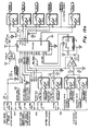
- FIG. 2 is a detailed block diagram of the external controller portion.
- the principal circuits comprising the invention are the receiver circuits 34, the transmitter circuits 40, the first process controller 50, electrically erasable programmable read only memories (EEPROMS) 52, 54, a keyboard interface 56, a real time clock 58, the LCD display circuitry 64, and a personal computer interface 60.
- the first antenna coil 32 connects to the transmitter portion 40 which includes a modulator 42, a radio frequency (RF) synthesizer 44, a driver 45, and a class D power amplifier 46.
- RF radio frequency
- FIG. 3 shows a schematic diagram of the RF synthesizer of the transmitter portion 40 of the external controller portion 22.
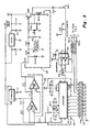
- the RF synthesizer 44 has several subcircuits comprised of the voltage controlled oscillator (VCO) 64, the phase locked loop 66, and the low pass filter 68.
- the phase locked loop integrated circuit 67 utilized in the preferred embodiment is a Motorola MC 145106.
- the integrated circuit 67 utilizes an external crystal with a frequency of 10.240 MHz.
- the integrated circuit 67 divides the 10.240 MHz frequency into an internal reference frequency which is compared to the frequency of the voltage controlled oscillator 64. The output of this comparison is the loop error voltage which goes from the integrated circuit 67 to the low pass filter 68 where the reference signal frequency component is removed.
- the error voltage is then applied to the voltage controlled oscillator 64 to adjust the frequency of the voltage controlled oscillator 64.
- the frequency of the RF synthesizer 44 is set at two MHz, however it is programmable by sending a frequency programming command from the control processor 50 to the phase locked loop integrated circuit 67.
- the programming connections of the integrated circuit 67 connect to the terminals on the CON1 connector 70.
- the corresponding terminals of CON1 connector 70 are on FIG. 11.
- the output of the voltage controlled oscillator 64 goes via conductor 64.1 to the CMOS buffer amp 69, a Maxim MAX626SMD integrated circuit, which has dual outputs, one output looping back to the integrated circuit 67 by way of conductor 69.1 and the other output providing a symmetrical RF signal through conductor 69.2 for the driver amplifier 72 and the power amplifier 46.
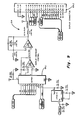
- the driver 72 and class D power amplifier 46 are shown.
- the driver amplifier 72 consists of a pair of bipolar transistors 72.1 and 72.2 and receives the RF signal from conductor 69.2 after it has passed through the buffer amplifier 71.
- the power amplifier is comprised of a pair of IRF510 power MOSFETS 46.1, 46.2 configured as a class D power amplifier 46.
- the output of the class D power amplifier 46 is connected through conductor 46.3 to a series resonant tank circuit comprised of the capacitors 75 and the first antenna coil 30.
- the first antenna coil 30 radiates the RF energy and couples with the second antenna coil 32 of the stimulator portion 24 when they are in proximity to each other.
- the tank circuit thus constitutes a tuned primary circuit 31.
- the two MHz radio frequency (RF) signal provides the power transfer for recharging the batteries of the implanted stimulator portion 24.
- the in-link telemetry modulation is provided by the modulator 42 which acts to switch the output of the voltage controlled oscillator 64 to ground, thus grounding the RF signal and eliminating the RF input to the drive amplifier 72 and the power amplifier 46.
- the modulator 42 in the embodiment shown consists of two Siliconix Si9955 metal-oxide-semiconductor field-effect transistors (MOSFETS) 42.1, 42.2 connected between the ground and the conductor 69.2, shown in FIG. 3.
- the operating signal for the modulator 42 designated "ETX" on FIGS. 3 and 4, is received by way of conductor 69.3, and is the serial data output from the control processor 50 containing the commands to be sent to the stimulator portion 24.
- the serial data operates to amplitude shift key the radio frequency output of the power amplifier 46.
- Conductor 69.3 connects to the CON1 connector 70 with the corresponding connecting terminal shown on FIG. 11.
- the serial data output constituting the in-link telemetry signal is designated "TX" on FIGS. 6b, 10 and 11.
- the receiver or out-link telemetry circuitry for the external controller portion 22 is also shown on FIG. 4.
- the transformer 78 has a single turn primary which picks up the current in conductor 46.3 and induces a voltage in the secondary of transformer 78.
- the voltage induced in the secondary of 78 fluctuates in accordance to the out-link telemetry signal from the stimulator portion 24 which is comprised of reflected RF energy.
- the method of reflecting and modulating the RF energy in the stimulator portion 24 is discussed below with reference to FIG. 13a.
- the envelope demodulator circuitry 36 detects the encoded signal, filters the rf, and provides the signal to the tracking and threshold detector 38.
- the tracking and threshold detector 38 compensates for variations in positional alignments between the first antenna coil 30 and the second antenna coil 32 and also compensates for motion between the coils 30, 32 during operation.
- the tracking and threshold detector 38 utilize three operational amplifiers 38.1, 38.2, 38.3 configured as an automatic gain control with a threshold crossing detector.
- the three operational amplifiers are available from Motorola Inc. and are identified as MC33172D, MC33172D, and LM311 respectively.
- the third operational amplifier 38.3 operates as a comparator, comparing an averaged value of the pulsed wave form to the actual serial pulse wave form, the output providing stable, uniform serial data pulses. The serial data pulses are then forwarded to the micro-controller 50 for processing.
- FIG. 5 shows a schematic of a programmable power supply for the external controller portion 22.
- the power supply supplies the necessary power for all of the circuits of the external controller portion 22.
- the output of the power supply is programmable to provide incrementally adjustable voltage to the class D power amplifier 46 by way of commands from the control processor 50 to integrated circuit 49 thereby adjusting the RF output level.
- Integrated circuit 49 is a CMOS analog switch available through Maxim Integrated Products, 120 San Gabriel Drive, Sunnyvale, CA 94086.
- the power supply requires 12 volt input at terminal 22.7.
- the control lines for the integrated circuit 49 connect to the CON2 connector 49.
- the CON2 connector 49 with the connecting terminals is on FIG. 11.
- FIGS. 6a, 6b, 7, 8, 9, 10, and 11 show schematic drawings of the control processor circuitry and the related operating and memory circuitry for the external controller portion 22.
- the various signal lines on the figures showing the digital circuitry, FIGS. 6a, 6b, 7, 8, 9, 10, 11, 14, 15, and 16, are labeled with conventional terminology.
- the labels enclosed in ovals indicate that that specific line connects to all other like-labeled lines.
- the control processor 50 utilized in the preferred embodiment is a Motorola, Inc. MC 68332 integrated circuit.
- the MC 68332 is a 32 bit micro-controller with 2K bytes of fast static RAM, an asynchronous serial interface, a synchronous serial interface, a time processor unit, seven interrupt lines, chip select outputs, and bus control circuitry.
- the address bus 53 and data bus 51 connect the first control processor 50 to the system static RAM 55 comprised of four HM628128 integrated circuits.
- FIG. 8 also shows the real time clock 58 with battery back up allowing data recorded to be time stamped.
- the address bus 53 and data bus 51 also connect the first control processor 50 to the program ROM circuitry 57 comprised of four 28F020 FLASH EEPROM (electrically erasable programmable read only memory) integrated circuits.
- the FLASH memory allows the programming to be stored indefinitely.
- the Programs may be modified by way of a personal computer serially connected to the first control processor 50 by way of the personal computer interface 60 shown in FIG. 11.
- FIG. 9 shows the LCD display circuitry 64.
- the LCD is not shown but is of conventional design and is connected by way of the J4 connector 64.2. Contrast is controlled by way of a digital/analog converter 64.1 manufactured by Analog Services, Inc., One Technology Way, Norwood, Massachusetts 02062.
- FIG. 10a shows the circuitry for the downloading and debugging port for connection with an external personal computer through the J1 connector 60.5.
- the serial data signals containing the in-link and out-link telemetry data designated "TX" and "RX” go through the 232 converter 60.5, manufactured by Maxim Integrated Products, Inc., for compatibility with the personal computer.
- the other signal lines to and from the first control processor 50 are appropriately conditioned.
- FIG. 10b shows the circuit location for the keyboard switches (not shown) for operating the external control portion 24 at the J2 connector 56.
- the signal lines 56.5 connect to the first control processor 50 shown on FIG. 6b.
- FIG. 10b also shows the J3 connector 60.3 for connecting a power On/Off switch (not shown) and an "enter" switch (not shown).
- FIG. 11a shows the circuitry for interfacing the device with a personal computer.
- the 25 pin J1 connector 60.7 provides the direct linkage with the personal computer.
- the CON1 connector 70 and the CON2 connector 49 which connect the RF telemetry and power supply circuits to the digital circuits and two latches 64.7, 64.8.
- FIG 11b shows an additional 232 converter 60.9 and terminals for the J2 connector 56 also shown in FIG. 10a.
- the 232 converter 60.9 is also manufactured by Maxim Integrated Products, Inc.
- the first antenna coil 30 couples with the second antenna 32 coil to transcutaneously provide power for recharging the batteries of the stimulator portion 24 and to provide in-link and out-link telemetry.
- the antenna coils are configured in series tuned circuits which provide a low impedance primary tuned circuit 31 which is desirable for operation with the class D power amplifier 46 and a low impedance secondary tuned circuit 33 which is compatible to the secondary tuned circuit load.
- first and second antenna coils 30, 32 were dependant on the load presented to the second antenna coil, the circuit configurations, the coupling coefficient, the inductances and the desired physical dimensions.
- An appropriate size for the second antenna coil 32 for the implantable stimulator portion 24 was determined to be one inch. Extensive analysis and experimentation yielded the values for the preferred embodiment which are presented in Table 1 below.
- TABLE 1 First Antenna Coil 30 Second Antenna Coil 32 Coil diameter 1.25 in. 1.00 in. Axial thickness 0.125 in. 0.125 in. Radial thickness 0.025 in. 0.025 in. No. of turns 10 turns 13 turns Wire Litz Wire AWG No. 30 copper Inductance 5.8 ⁇ H 8.0 ⁇ H
- the Litz wire for the first antenna coil is comprised of single nylon polyester covered copper wire, 175 strands of AWG 48, available from Kerrigan-Lewis, Inc.
- the above design provides adequate tolerance room for variation in coil separation and misalignment.
- the design separation between the coils is 1/4 inch, however, the device will operate satisfactorily with significant variation from this dimension.
- the first antenna coil in the preferred embodiment is encapsulated in silicon rubber and is connected by way of cable to the external controller portion 22. Attachment to the skin of the patient for recharging and/or telemetry may be accomplished by way of adhesive tape or other products such as TegadermTM available from Minnesota Mining and Manufacturing Company, St. Paul, Minnesota.
- the second antenna coil is included in the stimulator encapsulated portion 24.
- FIG. 12 shows a detailed block diagram for the implantable stimulator portion 4.
- the second antenna coil 32 is connected to the battery charging circuits 80 for providing the power to recharge the batteries 28; the antenna coil 32 is connected to the envelope demodulator 82 and threshold detector 84 to provide the in-link telemetry; and the antenna coil 32 is also connected to the passive telemetry transmitter 86 to provide the out-link telemetry.
- the envelope demodulator 82 and threshold detector 84 input to the serial interface portion of the second control processor 90 for processing the in-link telemetry.
- the serial interface of the second control processor provides the out-link telemetry data to the passive telemetry transmitter 86.
- the second control processor 90 further receives data from the charging sense circuits 92, electrode current and voltage data from the electrode current and voltage sense circuits 94. The data is input into the analog-to-digital converter portion of the second control processor 90.
- the second control processor 90 controls the output of the electrodes 26 by way of the digital/analog circuits 98, the current mirror 97, and the analog switches 95.
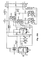
- FIG. 13a shows a schematic diagram of the circuitry for a preferred embodiment for the passive telemetry transmitter 86, the envelope demodulator 82, threshold detector 84, the battery charging circuits 80, and the rechargeable battery pack 29.
- the second antenna coil 32 is shown in series with capacitor 96 forming the secondary tuned circuit 33.
- the secondary tuned circuit 33 is connected to a full wave bridge rectifier circuit 93 and filtering capacitors 93.1 which comprise the battery charging circuits 80.
- the full wave bridge rectifier is connected to the battery pack 29 by way of conductors 93.4 and 93.5.
- the batteries 81 are nickel metal hydride (NiMH) rechargeable battery cells, size AA, and with a voltage output of 1.2 volts.
- NiMH nickel metal hydride
- the battery pack 29 also includes circuit breakers 29.1 to protect against excessive current.
- the devices in the preferred embodiment are identified as T4040 PTC, manufactured by the Thermacon Company, and are solid state and automatically reset.
- a temperature sensor 92.1 for monitoring battery temperatures while recharging.
- the temperature sensor along with conductors 92.2, 92.3, 92.4, and 92.5 comprise the charging sense circuits. Conductors 92.4 and 92.5 are connected to the temperature sensor 92.1. Conductors 92.2 and 92.3 are connected to the battery cells 81.
- the passive telemetry transmitter 86 is comprised of a pair of MOSFET transistors 86.1, 86.2 which are connected across the tuned secondary circuit 33 so that when they are switched "on" the tuned secondary circuit 33 is short circuited.
- the first antenna coil 30 and second antenna coil 32 couple when they are in proximity to each other.
- the short circuiting of the tuned secondary circuit 97 operates to reflect electromagnetic radiation back to the tuned primary circuit 31 which is otherwise absorbed by the tuned secondary circuit 32 and connected circuitry.
- the MOSFETS 86.1, 86.2 are switched in accordance with a signal conveyed on conductor 86.5 from the second control processor 90 to generate the encoded out-link telemetry signal labeled "TX" on FIG. 13a.
- Conductor 86.5 connects to J11 connector 99 which has corresponding terminals shown on FIG. 15.
- the MOSFETS 86.1, 86.2 shown in the preferred embodiment of the passive transmitter are Siliconix Si9955 transistors. In that these MOSFET switches have extremely low power drain and the actual medium which is utilized to transmit the out-link telemetry is RF power reflected from the external controller portion 22, the transmitter is passive and the battery consumption of the out-link telemetry is negligible.
- the MOSFETS are operated by the second control processor 90 at a rate of 4800 baud.
- the envelope demodulator and threshold detector 82 is also shown on FIG. 16a.
- Transformer 85 has a single wire primary 85.6 and a secondary that is in parallel with capacitor 85.1 forming a tuned circuit.
- the tuned circuit is connected to a pair of diodes 85.2 and additional RC circuitry whereby the in-link telemetry signal is detected and shaped.
- the signal then goes to the threshold detector 84 comprised of a MOSFET.
- the threshold detector 84 presents the received in-link telemetry signal labeled "RX" to the second control processor 90.
- the conductors for the envelope demodulator and threshold detector 82, and the charging sense circuits 92, connect to the connector 99 which has the corresponding terminals shown in FIG. 15.
- FIG. 13b shows the circuitry for system voltage and boost converters 91 for the implantable stimulator portion 24.
- Battery voltage of 2.2 volts is provided from conductor 91.1.
- the 2.2 volts is boosted to provide system power and the power for the electrodes 26.
- Power output for the electrodes 26 is switched by way of the MOSFETS 91.5, 91.6 and is controlled by the second control processor 90.
- the terminal connections for the system voltage boost converters circuitry 91 is also at the connector 99 with the corresponding terminal connections shown in FIG. 15.
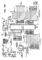
- FIG. 14 shows the second control processor 90 and related circuitry.
- the second control processor 90 used in the preferred embodiment is a Motorola Semiconductor Inc. microcontroller No. 68HC805C4.
- the microcontroller has a system RAM, bootstrap ROM, EEPROM bank A, EEPROM bank B, a synchronous serial port, 24 general input/output pins and an interrupt controller.
- a Motorola Semiconductor Technical Data document No. AD1991R2, by Motorola, Inc., 1985, distributed by Motorola Literature Distribution.
- FIG. 14 also shows the digital analog circuitry 98 comprised of the DAC8143 D/A converter 98.1, current reference integrated circuit 98.2, the current mirror 97, and the analog switches 95.
- the second control processor 90 is connected to the analog switches by way of electrode drive bus 90.5.
- the drive bus 90.5 connects to the operating terminals 95.1 of the analog switches 95.
- the output of the analog switches goes to the electrode cable 26.1 and the electrodes 26.
- the current reference integrated circuit 98.2 supplies a maximum reference current to the converter. In the preferred embodiment 400 ⁇ A was used.
- the digital/analog converter 98.1 provides 100 output current levels at output 98.5. This output is presented to the current mirror 97 which provides a constant current source independent of the load with a gain of four.
- the control processor 90 directly controls the digital/analog converter 98.1
- FIG. 15a shows an analog-to-digital converter integrated circuit 80, with inputs for battery voltage 80.1, 80.2, battery temperature 80.3, electrode drive voltage 80.4, receiver RF signal strength 80.5, and circuit board temperature 80.6.
- the output 80.7 of the converter 80 goes to the second control processor 90.
- the control processor 90 selects the specific parameter to input by way of "DIN" line 80.8.
- power to the converter 80 and the various inputs and outputs is switched under the control of the control processor 90.
- FIG. 15 shows the connections to the J11 connector 99.
- the electrical stimulus to the neural tissue is provided by the electrodes 26 attached to the stimulator portion 24.
- the potential to the electrodes 26 is provided through the analog switches 95.
- the second control processor 90 is appropriately programmed to control the analog switches to generate the stimuli with the specified parameters, i.e., monophasic, bi-phasic, direct current pulses, and with the specified amplitude and duration.
- the parameters of the stimuli are changed by way of digitally encoded commands from the external controller portion 22 through the in-link telemetry system.
- the in-link telemetry is accomplished by the first control processor 50 being programmed to encode commands and operate the modulator 42 to amplitude shift key the RF signal generated by RF synthesizers 45.
- the modulated RF signal goes to the first primary tuned circuit 31 which includes the first antenna coil 30.
- the first antenna coil 30 and second antenna coil 32 couple when in proximity to each other transferring the RF energy to tuned secondary circuit 33 of the stimulator portion 24.
- the envelope demodulator 82 and threshold detector 84 detect and shape the encoded signal by way of the rectifier, RC circuitry, and transfers the signal to the second control processor 90.
- the second control processor 90 in the stimulator portion 24 is programmed to receive and decode the commands and controls the analog-to-digital converter 98.1 and the analog switches 95 to alter the stimuli parameters as commanded.
- the first control processor 50 in the external controller portion 22 also is programmed to send commands requesting data on the battery voltage, battery temperature, circuit board temperature, electrode voltage, and the stimuli parameters.
- the second control processor 90 is programmed to enable the analog-to-digital converter 80 and the appropriate sensors to receive data on the requested conditions.
- the second control processor then encodes the data and operates the out-link telemetry to transmit the data to the external controller portion.
- Out-link telemetry transmission is accomplished by the second control processor 90 switching the MOSFETS 86.1 and 86.2 ON and OFF in accordance with encoded data when the first and second antenna coils are coupled.
- the switch short circuits the tuned secondary circuit 33 and reflects back RF energy to the first antenna coil 30.
- the external controller portion 22 receives the encoded out-link telemetry signal, and detects and demodulates the signal by way of the receiver circuitry 34.
- the first control processor 50 then decodes the data and stores the data in the system static RAM 55 and/or enables the LCD display circuitry 64 to display the data.
Landscapes
- Health & Medical Sciences (AREA)
- Engineering & Computer Science (AREA)
- Biomedical Technology (AREA)
- Nuclear Medicine, Radiotherapy & Molecular Imaging (AREA)
- Radiology & Medical Imaging (AREA)
- Life Sciences & Earth Sciences (AREA)
- Animal Behavior & Ethology (AREA)
- General Health & Medical Sciences (AREA)
- Public Health (AREA)
- Veterinary Medicine (AREA)
- Electrotherapy Devices (AREA)
Applications Claiming Priority (2)
| Application Number | Priority Date | Filing Date | Title |
|---|---|---|---|
| US44634 | 1987-05-01 | ||
| US08/044,634 US5314457A (en) | 1993-04-08 | 1993-04-08 | Regenerative electrical |
Publications (2)
| Publication Number | Publication Date |
|---|---|
| EP0619123A2 true EP0619123A2 (fr) | 1994-10-12 |
| EP0619123A3 EP0619123A3 (en) | 1997-08-06 |
Family
ID=21933450
Family Applications (1)
| Application Number | Title | Priority Date | Filing Date |
|---|---|---|---|
| EP94400761A Withdrawn EP0619123A3 (en) | 1993-04-08 | 1994-04-07 | Regenerative electrical stimulator. |
Country Status (3)
| Country | Link |
|---|---|
| US (1) | US5314457A (fr) |
| EP (1) | EP0619123A3 (fr) |
| CA (1) | CA2120818C (fr) |
Cited By (6)
| Publication number | Priority date | Publication date | Assignee | Title |
|---|---|---|---|---|
| EP1598092A3 (fr) * | 2000-04-28 | 2005-12-21 | Medtronic, Inc. | Management du chargement d'une batterie pour un dispositif implantable |
| US7225032B2 (en) | 2003-10-02 | 2007-05-29 | Medtronic Inc. | External power source, charger and system for an implantable medical device having thermal characteristics and method therefore |
| EP2020923A2 (fr) | 2006-05-04 | 2009-02-11 | Cambridge Temperature Concepts Limited | Mesure in situ de paramètres physiques |
| US7505816B2 (en) | 2005-04-29 | 2009-03-17 | Medtronic, Inc. | Actively cooled external energy source, external charger, system of transcutaneous energy transfer, system of transcutaneous charging and method therefore |
| US8005547B2 (en) | 2003-10-02 | 2011-08-23 | Medtronic, Inc. | Inductively rechargeable external energy source, charger, system and method for a transcutaneous inductive charger for an implantable medical device |
| US8496597B2 (en) | 2006-09-05 | 2013-07-30 | Fertility Focus Limited | Method of detecting and predicting ovulation and the period of fertility |
Families Citing this family (191)
| Publication number | Priority date | Publication date | Assignee | Title |
|---|---|---|---|---|
| US5579775A (en) * | 1994-10-20 | 1996-12-03 | Hewlett-Packard Company | Dynamic control of a patient monitoring system |
| US5630836A (en) * | 1995-01-19 | 1997-05-20 | Vascor, Inc. | Transcutaneous energy and information transmission apparatus |
| US5584870A (en) * | 1995-03-09 | 1996-12-17 | Cochlear Ltd. | Implant ESD protection network |
| WO1997009012A1 (fr) * | 1995-09-05 | 1997-03-13 | Cochlear Pty. Limited | Multiplexeur percutane pour dispositifs therapeutiques |
| US5710863A (en) * | 1995-09-19 | 1998-01-20 | Chen; Juin-Hwey | Speech signal quantization using human auditory models in predictive coding systems |
| EP0764939B1 (fr) * | 1995-09-19 | 2002-05-02 | AT&T Corp. | Synthèse de signaux de parole en l'absence de paramètres codés |
| US5935078A (en) * | 1996-01-30 | 1999-08-10 | Telecom Medical, Inc. | Transdermal communication system and method |
| US5861018A (en) * | 1996-05-28 | 1999-01-19 | Telecom Medical Inc. | Ultrasound transdermal communication system and method |
| US5733313A (en) * | 1996-08-01 | 1998-03-31 | Exonix Corporation | RF coupled, implantable medical device with rechargeable back-up power source |
| US5735887A (en) * | 1996-12-10 | 1998-04-07 | Exonix Corporation | Closed-loop, RF-coupled implanted medical device |
| US5814089A (en) * | 1996-12-18 | 1998-09-29 | Medtronic, Inc. | Leadless multisite implantable stimulus and diagnostic system |
| US6164284A (en) * | 1997-02-26 | 2000-12-26 | Schulman; Joseph H. | System of implantable devices for monitoring and/or affecting body parameters |
| EP1424098B1 (fr) * | 1997-08-01 | 2008-12-03 | Alfred E. Mann Foundation For Scientific Research | Dispositif implantable à configuration améliorée d'alimentation et de recharge de batterie |
| EP0999874B1 (fr) * | 1997-08-01 | 2004-09-29 | Alfred E. Mann Foundation For Scientific Research | Dispositif implantable a configuration amelioree d'alimentation et de recharge de batterie |
| US6585763B1 (en) * | 1997-10-14 | 2003-07-01 | Vascusense, Inc. | Implantable therapeutic device and method |
| US6140740A (en) | 1997-12-30 | 2000-10-31 | Remon Medical Technologies, Ltd. | Piezoelectric transducer |
| US6431175B1 (en) | 1997-12-30 | 2002-08-13 | Remon Medical Technologies Ltd. | System and method for directing and monitoring radiation |
| US6475170B1 (en) | 1997-12-30 | 2002-11-05 | Remon Medical Technologies Ltd | Acoustic biosensor for monitoring physiological conditions in a body implantation site |
| US6486588B2 (en) * | 1997-12-30 | 2002-11-26 | Remon Medical Technologies Ltd | Acoustic biosensor for monitoring physiological conditions in a body implantation site |
| US20030036746A1 (en) | 2001-08-16 | 2003-02-20 | Avi Penner | Devices for intrabody delivery of molecules and systems and methods utilizing same |
| US5945762A (en) * | 1998-02-10 | 1999-08-31 | Light Sciences Limited Partnership | Movable magnet transmitter for inducing electrical current in an implanted coil |
| US6281611B1 (en) | 1998-02-10 | 2001-08-28 | Light Sciences Corporation | Use of moving element to produce heat |
| US6331744B1 (en) | 1998-02-10 | 2001-12-18 | Light Sciences Corporation | Contactless energy transfer apparatus |
| DE69830203T2 (de) | 1998-02-23 | 2006-01-12 | Medtronic, Inc., Minneapolis | Implantierbare medizinische vorrichtung mit hochfrequenz-einkopplung zum aufladen der energiequelle |
| US6308101B1 (en) | 1998-07-31 | 2001-10-23 | Advanced Bionics Corporation | Fully implantable cochlear implant system |
| EP2325622B1 (fr) * | 1998-08-26 | 2014-03-12 | Sensors for Medicine and Science, Inc. | Dispositif de détection à base d'optique |
| US6304766B1 (en) | 1998-08-26 | 2001-10-16 | Sensors For Medicine And Science | Optical-based sensing devices, especially for in-situ sensing in humans |
| US7076307B2 (en) * | 2002-05-09 | 2006-07-11 | Boveja Birinder R | Method and system for modulating the vagus nerve (10th cranial nerve) with electrical pulses using implanted and external components, to provide therapy neurological and neuropsychiatric disorders |
| US6516227B1 (en) * | 1999-07-27 | 2003-02-04 | Advanced Bionics Corporation | Rechargeable spinal cord stimulator system |
| US7177690B2 (en) | 1999-07-27 | 2007-02-13 | Advanced Bionics Corporation | Implantable system having rechargeable battery indicator |
| US6277078B1 (en) | 1999-11-19 | 2001-08-21 | Remon Medical Technologies, Ltd. | System and method for monitoring a parameter associated with the performance of a heart |
| US6477425B1 (en) * | 1999-12-23 | 2002-11-05 | Mmc/Gatx Partnership No. 1 | External transmitter for implanted medical device |
| US6733446B2 (en) * | 2000-01-21 | 2004-05-11 | Medtronic Minimed, Inc. | Ambulatory medical apparatus and method using a telemetry system with predefined reception listening periods |
| US7742811B2 (en) * | 2000-03-13 | 2010-06-22 | Onco Stim | Implantable device and method for the electrical treatment of cancer |
| US8024048B2 (en) * | 2000-03-13 | 2011-09-20 | Ionix Medical Inc. | Method and device for treating cancer with electrical therapy in conjunction with chemotherapeutic agents and radiation therapy |
| US6772026B2 (en) | 2000-04-05 | 2004-08-03 | Therics, Inc. | System and method for rapidly customizing design, manufacture and/or selection of biomedical devices |
| US6478820B1 (en) | 2000-04-25 | 2002-11-12 | The Penn State Research Foundation | Artificial heart with synchronous rectification |
| US6458164B1 (en) | 2000-04-25 | 2002-10-01 | The Penn State Research Foundation | Artificial heart with energy recovery |
| US6451055B1 (en) | 2000-04-25 | 2002-09-17 | The Penn State Research Foundation | Artificial heart data communication system |
| US6579315B1 (en) | 2000-04-25 | 2003-06-17 | The Penn State Research Foundation | Artificial heart power supply system |
| US6395027B1 (en) | 2000-04-25 | 2002-05-28 | The Penn State Research Foundation | Artificial heart with arrhythmia signalling |
| US6850803B1 (en) | 2000-06-16 | 2005-02-01 | Medtronic, Inc. | Implantable medical device with a recharging coil magnetic shield |
| US6505077B1 (en) | 2000-06-19 | 2003-01-07 | Medtronic, Inc. | Implantable medical device with external recharging coil electrical connection |
| EP1166820B1 (fr) * | 2000-06-19 | 2009-09-30 | Medtronic, Inc. | Dispositif médical implantable comportant une bobine de recharge externe |
| US7553280B2 (en) * | 2000-06-29 | 2009-06-30 | Sensors For Medicine And Science, Inc. | Implanted sensor processing system and method |
| US6400974B1 (en) | 2000-06-29 | 2002-06-04 | Sensors For Medicine And Science, Inc. | Implanted sensor processing system and method for processing implanted sensor output |
| US7024248B2 (en) | 2000-10-16 | 2006-04-04 | Remon Medical Technologies Ltd | Systems and methods for communicating with implantable devices |
| US6889086B2 (en) * | 2001-04-06 | 2005-05-03 | Cardiac Pacemakers, Inc. | Passive telemetry system for implantable medical device |
| AU2002256413B2 (en) | 2001-05-04 | 2007-06-07 | Sensors For Medicine And Science, Inc. | Electro-optical sensing device with reference channel |
| US8065014B2 (en) * | 2001-06-21 | 2011-11-22 | Vanderbilt University | Method for promoting selective reinnervation of denervated tissue |
| AU2003299471A1 (en) * | 2002-05-07 | 2004-05-13 | Kai Kroll | Method and device for treating concer with electrical therapy in conjunction with chemotherapeutic agents and radiation therapy |
| US7076304B2 (en) * | 2003-04-07 | 2006-07-11 | Kidney Replacement Services P.C. | Transcutaneous power supply |
| AU2003904303A0 (en) * | 2003-08-12 | 2003-08-28 | National Ageing Research Institute Incorporated | Nerve function and tissue healing |
| US7272445B2 (en) * | 2003-10-02 | 2007-09-18 | Medtronic, Inc. | Medical device programmer with faceplate |
| US7203549B2 (en) * | 2003-10-02 | 2007-04-10 | Medtronic, Inc. | Medical device programmer with internal antenna and display |
| US8265770B2 (en) * | 2003-10-02 | 2012-09-11 | Medtronic, Inc. | Driver circuitry switchable between energy transfer and telemetry for an implantable medical device |
| US7308316B2 (en) * | 2003-10-02 | 2007-12-11 | Medtronic, Inc. | Storable implantable medical device assembly allowing in package charging |
| US7286880B2 (en) * | 2003-10-02 | 2007-10-23 | Medtronic, Inc. | System and method for transcutaneous energy transfer achieving high efficiency |
| US7991479B2 (en) * | 2003-10-02 | 2011-08-02 | Medtronic, Inc. | Neurostimulator programmer with clothing attachable antenna |
| US7286881B2 (en) * | 2003-10-02 | 2007-10-23 | Medtronic, Inc. | External power source having an adjustable magnetic core and method of use |
| US7515967B2 (en) * | 2003-10-02 | 2009-04-07 | Medtronic, Inc. | Ambulatory energy transfer system for an implantable medical device and method therefore |
| US7729766B2 (en) | 2003-10-02 | 2010-06-01 | Medtronic, Inc. | Circuit board construction for handheld programmer |
| US7561921B2 (en) * | 2003-10-02 | 2009-07-14 | Medtronic, Inc. | Neurostimulator programmer with internal antenna |
| US7263406B2 (en) * | 2003-10-02 | 2007-08-28 | Medtronic, Inc. | Medical device programmer with selective disablement of display during telemetry |
| US8140168B2 (en) | 2003-10-02 | 2012-03-20 | Medtronic, Inc. | External power source for an implantable medical device having an adjustable carrier frequency and system and method related therefore |
| US20050075685A1 (en) * | 2003-10-02 | 2005-04-07 | Forsberg John W. | Medical device programmer with infrared communication |
| US20050222646A1 (en) * | 2004-04-06 | 2005-10-06 | Kai Kroll | Method and device for treating cancer with modified output electrical therapy |
| US7720549B2 (en) * | 2004-04-06 | 2010-05-18 | Oncostim, Inc. | Partially implantable system for the electrical treatment of abnormal tissue growth |
| US8041427B2 (en) * | 2004-04-30 | 2011-10-18 | Medtronic, Inc. | Battery isolator for implantable medical device |
| US20050245982A1 (en) * | 2004-04-30 | 2005-11-03 | Medtronic, Inc. | Connector block for an implantable medical device |
| US7236869B2 (en) * | 2004-04-30 | 2007-06-26 | General Motors Corporation | Blended torque estimation for automatic transmission systems |
| US7512443B2 (en) * | 2004-04-30 | 2009-03-31 | Medtronic, Inc. | Spacers for use with transcutaneous energy transfer system |
| US7123966B2 (en) * | 2004-04-30 | 2006-10-17 | Medtronic, Inc. | Drop and slide engagement for implantable medical device |
| US7442337B2 (en) * | 2004-04-30 | 2008-10-28 | Medtronic, Inc. | Method of laminating articles |
| US7035688B2 (en) * | 2004-04-30 | 2006-04-25 | Medtronic, Inc. | Laminate of magnetic material and method of making |
| US7955543B2 (en) * | 2004-04-30 | 2011-06-07 | Medtronic, Inc. | Method of overmolding a substrate |
| US7794499B2 (en) * | 2004-06-08 | 2010-09-14 | Theken Disc, L.L.C. | Prosthetic intervertebral spinal disc with integral microprocessor |
| WO2006014687A1 (fr) * | 2004-07-20 | 2006-02-09 | Medtronic, Inc. | Telemetrie faisant appel a la puissance commutee dans un dispositif medical implantable |
| US20060020302A1 (en) * | 2004-07-20 | 2006-01-26 | Medtronic, Inc. | Medical device telemetry arbitration system based upon user selection |
| US20060020303A1 (en) * | 2004-07-20 | 2006-01-26 | Medtronic, Inc. | Medical device telemetry arbitration system using signal strength |
| US20060020304A1 (en) * | 2004-07-20 | 2006-01-26 | Medtronic, Inc. | Medical device telemetry arbitration system using time of response |
| US20060064142A1 (en) | 2004-09-17 | 2006-03-23 | Cardiac Pacemakers, Inc. | Systems and methods for deriving relative physiologic measurements using an implanted sensor device |
| US7720546B2 (en) * | 2004-09-30 | 2010-05-18 | Codman Neuro Sciences Sárl | Dual power supply switching circuitry for use in a closed system |
| US7544171B2 (en) * | 2004-10-22 | 2009-06-09 | General Patent Llc | Methods for promoting nerve regeneration and neuronal growth and elongation |
| US7497835B2 (en) * | 2004-10-22 | 2009-03-03 | General Patent Llc | Method of treatment for and prevention of periodontal disease |
| US7813808B1 (en) | 2004-11-24 | 2010-10-12 | Remon Medical Technologies Ltd | Implanted sensor system with optimized operational and sensing parameters |
| EP1838210B1 (fr) * | 2004-11-24 | 2010-10-13 | Remon Medical Technologies Ltd. | Dispositif medical implantable presentant un transducteur acoustique integre |
| US7522962B1 (en) | 2004-12-03 | 2009-04-21 | Remon Medical Technologies, Ltd | Implantable medical device with integrated acoustic transducer |
| US7775966B2 (en) | 2005-02-24 | 2010-08-17 | Ethicon Endo-Surgery, Inc. | Non-invasive pressure measurement in a fluid adjustable restrictive device |
| US7927270B2 (en) | 2005-02-24 | 2011-04-19 | Ethicon Endo-Surgery, Inc. | External mechanical pressure sensor for gastric band pressure measurements |
| US8066629B2 (en) | 2005-02-24 | 2011-11-29 | Ethicon Endo-Surgery, Inc. | Apparatus for adjustment and sensing of gastric band pressure |
| US7699770B2 (en) | 2005-02-24 | 2010-04-20 | Ethicon Endo-Surgery, Inc. | Device for non-invasive measurement of fluid pressure in an adjustable restriction device |
| US8016744B2 (en) | 2005-02-24 | 2011-09-13 | Ethicon Endo-Surgery, Inc. | External pressure-based gastric band adjustment system and method |
| US7775215B2 (en) | 2005-02-24 | 2010-08-17 | Ethicon Endo-Surgery, Inc. | System and method for determining implanted device positioning and obtaining pressure data |
| US7658196B2 (en) | 2005-02-24 | 2010-02-09 | Ethicon Endo-Surgery, Inc. | System and method for determining implanted device orientation |
| US7909754B2 (en) * | 2005-02-24 | 2011-03-22 | Ethicon Endo-Surgery, Inc. | Non-invasive measurement of fluid pressure in an adjustable gastric band |
| US20060194724A1 (en) * | 2005-02-25 | 2006-08-31 | Whitehurst Todd K | Methods and systems for nerve regeneration |
| US7988648B2 (en) * | 2005-03-04 | 2011-08-02 | General Patent, Llc | Pancreas regeneration treatment for diabetics using extracorporeal acoustic shock waves |
| US7308292B2 (en) | 2005-04-15 | 2007-12-11 | Sensors For Medicine And Science, Inc. | Optical-based sensing devices |
| US7774069B2 (en) * | 2005-04-29 | 2010-08-10 | Medtronic, Inc. | Alignment indication for transcutaneous energy transfer |
| US8571666B2 (en) * | 2005-08-02 | 2013-10-29 | William F. Urmey | Nerve stimulation system with programmed pulse charge attenuation |
| US7615012B2 (en) * | 2005-08-26 | 2009-11-10 | Cardiac Pacemakers, Inc. | Broadband acoustic sensor for an implantable medical device |
| US7570998B2 (en) * | 2005-08-26 | 2009-08-04 | Cardiac Pacemakers, Inc. | Acoustic communication transducer in implantable medical device header |
| WO2007028226A1 (fr) * | 2005-09-09 | 2007-03-15 | Ibm Canada Limited - Ibm Canada Limitee | Procede et systeme pour la traduction de machine d'etats |
| US7742815B2 (en) | 2005-09-09 | 2010-06-22 | Cardiac Pacemakers, Inc. | Using implanted sensors for feedback control of implanted medical devices |
| PT103374A (pt) * | 2005-10-28 | 2007-04-30 | Abreu Antonio Manuel Sequeira | Carregador de bateria para implantes cardíacos |
| US7596414B2 (en) * | 2005-12-05 | 2009-09-29 | Boston Scientific Neuromodulation Corporation | Cuff electrode arrangement for nerve stimulation and methods of treating disorders |
| US7610103B2 (en) * | 2005-12-19 | 2009-10-27 | Boston Scientific Neuromodulation Corporation | Electrode arrangement for nerve stimulation and methods of treating disorders |
| CN100444783C (zh) * | 2005-12-30 | 2008-12-24 | 东南大学 | 微电子系统辅助神经信道功能恢复方法及其装置 |
| US7953498B1 (en) * | 2006-03-15 | 2011-05-31 | Boston Scientific Neuromodulation Corporation | Resorbable anchor arrangements for implantable devices and methods of making and using |
| US7974706B2 (en) * | 2006-03-30 | 2011-07-05 | Boston Scientific Neuromodulation Corporation | Electrode contact configurations for cuff leads |
| US8870742B2 (en) | 2006-04-06 | 2014-10-28 | Ethicon Endo-Surgery, Inc. | GUI for an implantable restriction device and a data logger |
| US8152710B2 (en) | 2006-04-06 | 2012-04-10 | Ethicon Endo-Surgery, Inc. | Physiological parameter analysis for an implantable restriction device and a data logger |
| US7738965B2 (en) * | 2006-04-28 | 2010-06-15 | Medtronic, Inc. | Holster for charging pectorally implanted medical devices |
| US20100152811A1 (en) * | 2006-06-30 | 2010-06-17 | Flaherty Christopher J | Nerve regeneration system and lead devices associated therewith |
| DE102006033623B4 (de) * | 2006-07-18 | 2010-04-08 | Cerbomed Gmbh | System zur transkutanen Stimulation eines Nervs des menschlichen Körpers |
| US7955268B2 (en) | 2006-07-21 | 2011-06-07 | Cardiac Pacemakers, Inc. | Multiple sensor deployment |
| US7912548B2 (en) * | 2006-07-21 | 2011-03-22 | Cardiac Pacemakers, Inc. | Resonant structures for implantable devices |
| WO2008011577A2 (fr) | 2006-07-21 | 2008-01-24 | Cardiac Pacemakers, Inc. | Transducteur à ultrasons pour un dispositif médical implanté à cavité métallique |
| US8244377B1 (en) | 2006-09-27 | 2012-08-14 | Boston Scientific Neuromodulation Corporation | Fixation arrangements for implantable leads and methods of making and using |
| US20080103557A1 (en) * | 2006-10-31 | 2008-05-01 | Medtronic, Inc. | Extended shelf life storable implantable medical device assembly, shipping container and method |
| US8290599B2 (en) | 2006-12-12 | 2012-10-16 | Boston Scientific Neuromodulation Corporation | Electrode arrangements for tissue stimulation and methods of use and manufacture |
| US9339643B1 (en) | 2007-03-30 | 2016-05-17 | Boston Scientific Neuromodulation Corporation | Acutely stiff implantable electrodes |
| US8825161B1 (en) | 2007-05-17 | 2014-09-02 | Cardiac Pacemakers, Inc. | Acoustic transducer for an implantable medical device |
| EP2162185B1 (fr) | 2007-06-14 | 2015-07-01 | Cardiac Pacemakers, Inc. | Système de recharge acoustique à plusieurs éléments |
| WO2009027755A1 (fr) * | 2007-08-28 | 2009-03-05 | Institut National De La Recherche Agronomique (Inra) | Dispositif et procédé de réduction de poids |
| US8498716B2 (en) | 2007-11-05 | 2013-07-30 | Boston Scientific Neuromodulation Corporation | External controller for an implantable medical device system with coupleable external charging coil assembly |
| US8187163B2 (en) | 2007-12-10 | 2012-05-29 | Ethicon Endo-Surgery, Inc. | Methods for implanting a gastric restriction device |
| US8100870B2 (en) | 2007-12-14 | 2012-01-24 | Ethicon Endo-Surgery, Inc. | Adjustable height gastric restriction devices and methods |
| US8377079B2 (en) | 2007-12-27 | 2013-02-19 | Ethicon Endo-Surgery, Inc. | Constant force mechanisms for regulating restriction devices |
| US8142452B2 (en) | 2007-12-27 | 2012-03-27 | Ethicon Endo-Surgery, Inc. | Controlling pressure in adjustable restriction devices |
| US8591395B2 (en) | 2008-01-28 | 2013-11-26 | Ethicon Endo-Surgery, Inc. | Gastric restriction device data handling devices and methods |
| US8337389B2 (en) | 2008-01-28 | 2012-12-25 | Ethicon Endo-Surgery, Inc. | Methods and devices for diagnosing performance of a gastric restriction system |
| US8192350B2 (en) | 2008-01-28 | 2012-06-05 | Ethicon Endo-Surgery, Inc. | Methods and devices for measuring impedance in a gastric restriction system |
| US8221439B2 (en) | 2008-02-07 | 2012-07-17 | Ethicon Endo-Surgery, Inc. | Powering implantable restriction systems using kinetic motion |
| US7844342B2 (en) | 2008-02-07 | 2010-11-30 | Ethicon Endo-Surgery, Inc. | Powering implantable restriction systems using light |
| US8114345B2 (en) | 2008-02-08 | 2012-02-14 | Ethicon Endo-Surgery, Inc. | System and method of sterilizing an implantable medical device |
| JP5211177B2 (ja) | 2008-02-11 | 2013-06-12 | カーディアック ペースメイカーズ, インコーポレイテッド | 心臓内の調律識別のための血行動態の監視方法 |
| US8591532B2 (en) | 2008-02-12 | 2013-11-26 | Ethicon Endo-Sugery, Inc. | Automatically adjusting band system |
| WO2009102640A1 (fr) | 2008-02-12 | 2009-08-20 | Cardiac Pacemakers, Inc. | Systèmes et procédés de commande de transferts de signaux sans fil entre des dispositifs médicaux fonctionnant par ultrasons |
| US8057492B2 (en) | 2008-02-12 | 2011-11-15 | Ethicon Endo-Surgery, Inc. | Automatically adjusting band system with MEMS pump |
| US8034065B2 (en) | 2008-02-26 | 2011-10-11 | Ethicon Endo-Surgery, Inc. | Controlling pressure in adjustable restriction devices |
| US8233995B2 (en) | 2008-03-06 | 2012-07-31 | Ethicon Endo-Surgery, Inc. | System and method of aligning an implantable antenna |
| US8187162B2 (en) | 2008-03-06 | 2012-05-29 | Ethicon Endo-Surgery, Inc. | Reorientation port |
| US7917226B2 (en) * | 2008-04-23 | 2011-03-29 | Enteromedics Inc. | Antenna arrangements for implantable therapy device |
| US10736689B2 (en) | 2008-08-20 | 2020-08-11 | Prostacare Pty Ltd | Low-corrosion electrode for treating tissue |
| EP2334230A1 (fr) | 2008-10-10 | 2011-06-22 | Cardiac Pacemakers, Inc. | Systèmes et procédés de détermination de sortie cardiaque à l'aide de mesures de pression artérielle pulmonaire |
| WO2010059291A1 (fr) | 2008-11-19 | 2010-05-27 | Cardiac Pacemakers, Inc. | Évaluation d'une résistance vasculaire pulmonaire par l'intermédiaire d'une pression artérielle pulmonaire |
| US8335569B2 (en) | 2009-02-10 | 2012-12-18 | Boston Scientific Neuromodulation Corporation | External device for communicating with an implantable medical device having data telemetry and charging integrated in a single housing |
| US9517352B2 (en) * | 2009-03-20 | 2016-12-13 | Medtronic, Inc. | Accessory apparatus for improved recharging of implantable medical device |
| WO2011097289A1 (fr) | 2010-02-03 | 2011-08-11 | Medtronic, Inc. | Dispositifs médicaux implantables et systèmes bi-fréquence de télémétrie inductive et de recharge |
| US9042995B2 (en) * | 2010-02-03 | 2015-05-26 | Medtronic, Inc. | Implantable medical devices and systems having power management for recharge sessions |
| US9136728B2 (en) | 2011-04-28 | 2015-09-15 | Medtronic, Inc. | Implantable medical devices and systems having inductive telemetry and recharge on a single coil |
| WO2013009881A2 (fr) | 2011-07-11 | 2013-01-17 | Vascor, Inc. | Transmission et communication de puissance par voie transcutanée pour un dispositif d'assistance cardiaque implanté et autres dispositifs |
| US8682444B2 (en) | 2011-12-21 | 2014-03-25 | Boston Scientific Neuromodulation Corporation | System for an implantable medical device having an external charger coupleable to accessory charging coils |
| US8886333B2 (en) | 2012-07-19 | 2014-11-11 | Boston Scientific Neuromodulation Corporation | Self-affixing external charging system for an implantable medical device |
| US8948871B2 (en) | 2012-07-26 | 2015-02-03 | Nyxoah SA | Electrical contacts on a medical device patch |
| US9209634B2 (en) | 2012-09-07 | 2015-12-08 | Greatbatch Ltd. | Method of improving battery recharge efficiency by statistical analysis |
| US9142989B2 (en) | 2012-09-07 | 2015-09-22 | Greatbatch Ltd. | Method of minimizing interruptions to implantable medical device recharging |
| US9225190B2 (en) | 2012-09-07 | 2015-12-29 | Manufacturers And Traders Trust Company | Implant current controlled battery charging based on temperature |
| US9887574B2 (en) | 2013-03-15 | 2018-02-06 | Globus Medical, Inc. | Spinal cord stimulator system |
| US9872997B2 (en) | 2013-03-15 | 2018-01-23 | Globus Medical, Inc. | Spinal cord stimulator system |
| US9440076B2 (en) | 2013-03-15 | 2016-09-13 | Globus Medical, Inc. | Spinal cord stimulator system |
| US9878170B2 (en) | 2013-03-15 | 2018-01-30 | Globus Medical, Inc. | Spinal cord stimulator system |
| US10149933B2 (en) | 2014-07-25 | 2018-12-11 | Minnetronix, Inc. | Coil parameters and control |
| US9855376B2 (en) | 2014-07-25 | 2018-01-02 | Minnetronix, Inc. | Power scaling |
| US9929584B2 (en) | 2014-10-30 | 2018-03-27 | Boston Scientific Neuromodulation Corporation | External charging coil assembly for charging a medical device |
| US10342908B2 (en) | 2015-01-14 | 2019-07-09 | Minnetronix, Inc. | Distributed transformer |
| US10406267B2 (en) * | 2015-01-16 | 2019-09-10 | Minnetronix, Inc. | Data communication in a transcutaneous energy transfer system |
| US10105545B2 (en) | 2015-03-12 | 2018-10-23 | Boston Scientific Neuromodulation Corporation | Assembly with a coaxial audio connector for charging an implantable medical device |
| DE102016106657A1 (de) | 2015-04-14 | 2016-10-20 | Minnetronix, Inc. | Repeater-resonanzkreis |
| US10814127B2 (en) | 2016-02-05 | 2020-10-27 | Boston Scientific Neuromodulation Corporation | Slotted sleeve neurostimulation device |
| AU2017220115B2 (en) | 2016-02-19 | 2019-11-21 | Boston Scientific Neuromodulation Corporation | Electrical stimulation cuff devices and systems |
| US10420939B2 (en) | 2016-03-31 | 2019-09-24 | The Cleveland Clinic Foundation | Nerve stimulation to promote neuroregeneration |
| CN108883286B (zh) * | 2016-03-31 | 2021-12-07 | 心脏起搏器股份公司 | 具有可充电电池的可植入医疗设备 |
| US11389370B2 (en) | 2016-04-18 | 2022-07-19 | Softwave Tissue Regeneration Technologies, Llc | Treatments for blood sugar levels and muscle tissue optimization using extracorporeal acoustic shock waves |
| US11389372B2 (en) | 2016-04-18 | 2022-07-19 | Softwave Tissue Regeneration Technologies, Llc | Acoustic shock wave therapeutic methods |
| US11389373B2 (en) | 2016-04-18 | 2022-07-19 | Softwave Tissue Regeneration Technologies, Llc | Acoustic shock wave therapeutic methods to prevent or treat opioid addiction |
| US11389371B2 (en) | 2018-05-21 | 2022-07-19 | Softwave Tissue Regeneration Technologies, Llc | Acoustic shock wave therapeutic methods |
| US11458069B2 (en) | 2016-04-18 | 2022-10-04 | Softwave Tissue Regeneration Technologies, Llc | Acoustic shock wave therapeutic methods to treat medical conditions using reflexology zones |
| US10493269B2 (en) | 2016-06-02 | 2019-12-03 | Boston Scientific Neuromodulation Corporation | Leads for electrostimulation of peripheral nerves and other targets |
| EP3452163A1 (fr) | 2016-07-29 | 2019-03-13 | Boston Scientific Neuromodulation Corporation | Systèmes et procédés de fabrication et d'utilisation d'un système de stimulation électrique pour une stimulation nerveuse périphérique |
| WO2018102773A1 (fr) | 2016-12-02 | 2018-06-07 | Boston Scientific Neuromodulation Corporation | Méthodes et systèmes permettant de sélectionner des paramètres de stimulation pour des dispositifs de stimulation électrique |
| US10568513B2 (en) * | 2017-03-07 | 2020-02-25 | The Alfred E. Mann Foundation For Scientific Research | Multiple implant communications with adjustable load modulation using modulation indices |
| US10589089B2 (en) | 2017-10-25 | 2020-03-17 | Epineuron Technologies Inc. | Systems and methods for delivering neuroregenerative therapy |
| CA3079849A1 (fr) | 2017-10-25 | 2019-05-02 | Epineuron Technologies Inc. | Systemes et procedes d'administration de therapie anti-neurodegenerative |
| US11457975B2 (en) | 2017-11-27 | 2022-10-04 | Prostacare Pty Ltd | Apparatus and a method for the treatment of a prostatic disease |
| WO2019168949A1 (fr) | 2018-02-28 | 2019-09-06 | Prostacare Pty Ltd | Système de gestion des grandes variations d'impédance dans un système d'ablation non thermique pour hbp |
| US11247043B2 (en) | 2019-10-01 | 2022-02-15 | Epineuron Technologies Inc. | Electrode interface devices for delivery of neuroregenerative therapy |
| AU2022277556B2 (en) | 2021-05-21 | 2025-03-06 | Boston Scientific Neuromodulation Corporation | Electrical stimulation cuff devices and systems with helical arrangement of electrodes |
| US12402898B2 (en) | 2023-01-27 | 2025-09-02 | Softwave Tissue Regeneration Technologies, Llc | Acoustic shock wave or pressure pulse treatment for proptosis or exophthalmos |
Family Cites Families (18)
| Publication number | Priority date | Publication date | Assignee | Title |
|---|---|---|---|---|
| US3195540A (en) * | 1963-03-29 | 1965-07-20 | Louis C Waller | Power supply for body implanted instruments |
| US4080558A (en) * | 1974-12-30 | 1978-03-21 | Gould Inc. | Defibrillator battery charger |
| US4194179A (en) * | 1977-11-18 | 1980-03-18 | Becton, Dickinson & Company | Active antenna for medical telemetry monitoring systems |
| US4281664A (en) * | 1979-05-14 | 1981-08-04 | Medtronic, Inc. | Implantable telemetry transmission system for analog and digital data |
| USRE32947E (en) * | 1980-09-30 | 1989-06-13 | Baptist Medical Center Of Oklahoma, Inc. | Magnetic transcutaneous mount for external device of an associated implant |
| US4374382A (en) * | 1981-01-16 | 1983-02-15 | Medtronic, Inc. | Marker channel telemetry system for a medical device |
| US4459989A (en) * | 1981-06-30 | 1984-07-17 | Neuromed, Inc. | Non-invasive multiprogrammable tissue stimulator and methods for use |
| US4561443A (en) * | 1983-03-08 | 1985-12-31 | The Johns Hopkins University | Coherent inductive communications link for biomedical applications |
| US4679560A (en) * | 1985-04-02 | 1987-07-14 | Board Of Trustees Of The Leland Stanford Junior University | Wide band inductive transdermal power and data link |
| US4681111A (en) * | 1985-04-05 | 1987-07-21 | Siemens-Pacesetter, Inc. | Analog and digital telemetry system for an implantable device |
| US4741341A (en) * | 1986-03-12 | 1988-05-03 | Siemens-Pacesetter, Inc. | Protection circuit and method for implanted ECG telemetry circuits |
| US4726378A (en) * | 1986-04-11 | 1988-02-23 | Minnesota Mining And Manufacturing Company | Adjustable magnetic supercutaneous device and transcutaneous coupling apparatus |
| US4809697A (en) * | 1987-10-14 | 1989-03-07 | Siemens-Pacesetter, Inc. | Interactive programming and diagnostic system for use with implantable pacemaker |
| US4969464A (en) * | 1988-03-25 | 1990-11-13 | Telectronics N.V. | Pacemaker with improved automatic output regulation |
| US4940052A (en) * | 1989-01-25 | 1990-07-10 | Siemens-Pacesetter, Inc. | Microprocessor controlled rate-responsive pacemaker having automatic rate response threshold adjustment |
| US5069210A (en) * | 1989-04-17 | 1991-12-03 | Jeutter Dean C | Cochlear implant employing frequency-division multiplexing and frequency modulation |
| US4979506A (en) * | 1989-08-08 | 1990-12-25 | Siemens-Pacesetter, Inc. | Self-test system and method for external programming device |
| FR2657479B1 (fr) * | 1990-01-19 | 1994-07-08 | Bertin & Cie | Dispositif de transmission bidirectionnelle d'informations a recepteur alimente par l'emetteur. |
-
1993
- 1993-04-08 US US08/044,634 patent/US5314457A/en not_active Expired - Lifetime
-
1994
- 1994-04-07 CA CA002120818A patent/CA2120818C/fr not_active Expired - Fee Related
- 1994-04-07 EP EP94400761A patent/EP0619123A3/en not_active Withdrawn
Cited By (20)
| Publication number | Priority date | Publication date | Assignee | Title |
|---|---|---|---|---|
| US7865245B2 (en) | 2000-04-28 | 2011-01-04 | Medtronic, Inc. | Battery recharge management for implantable medical device |
| US7167756B1 (en) | 2000-04-28 | 2007-01-23 | Medtronic, Inc. | Battery recharge management for an implantable medical device |
| US9492675B2 (en) | 2000-04-28 | 2016-11-15 | Medtronic, Inc. | Method of recharging a power source for implantable medical device |
| US8989869B2 (en) | 2000-04-28 | 2015-03-24 | Medtronic, Inc. | Battery recharge management for implantable medical device |
| EP1598092A3 (fr) * | 2000-04-28 | 2005-12-21 | Medtronic, Inc. | Management du chargement d'une batterie pour un dispositif implantable |
| US8554322B2 (en) | 2003-10-02 | 2013-10-08 | Medtronic, Inc. | Inductively rechargeable external energy source, charger, system and method for a transcutaneous inductive charger for an implantable medical device |
| US9463324B2 (en) | 2003-10-02 | 2016-10-11 | Medtronic, Inc. | Inductively rechargeable external energy source, charger, system and method for a transcutaneous inductive charger for an implantable medical device |
| US8165678B2 (en) | 2003-10-02 | 2012-04-24 | Medtronic, Inc. | Inductively rechargeable external energy source, charger and system for a transcutaneous inductive charger for an implantable medical device |
| US11318250B2 (en) | 2003-10-02 | 2022-05-03 | Medtronic, Inc. | Inductively rechargeable external energy source, charger, system and method for a transcutaneous inductive charger for an implantable medical device |
| US8005547B2 (en) | 2003-10-02 | 2011-08-23 | Medtronic, Inc. | Inductively rechargeable external energy source, charger, system and method for a transcutaneous inductive charger for an implantable medical device |
| US8725262B2 (en) | 2003-10-02 | 2014-05-13 | Medtronic, Inc. | Inductively rechargeable external energy source, charger, system and method for a transcutaneous inductive charger for an implantable medical device |
| US10369275B2 (en) | 2003-10-02 | 2019-08-06 | Medtronic, Inc. | Inductively rechargeable external energy source, charger, system and method for a transcutaneous inductive charger for an implantable medical device |
| US9821112B2 (en) | 2003-10-02 | 2017-11-21 | Medtronic, Inc. | Inductively rechargeable external energy source, charger, system and method for a transcutaneous inductive charger for an implantable medical device |
| US7225032B2 (en) | 2003-10-02 | 2007-05-29 | Medtronic Inc. | External power source, charger and system for an implantable medical device having thermal characteristics and method therefore |
| US7505816B2 (en) | 2005-04-29 | 2009-03-17 | Medtronic, Inc. | Actively cooled external energy source, external charger, system of transcutaneous energy transfer, system of transcutaneous charging and method therefore |
| US8540644B2 (en) | 2006-05-04 | 2013-09-24 | Cambridge Temperature Concepts Limited | System and method for estimating a basal body temperature and forming an indication of ovulation |
| EP2020923A2 (fr) | 2006-05-04 | 2009-02-11 | Cambridge Temperature Concepts Limited | Mesure in situ de paramètres physiques |
| US9155522B2 (en) | 2006-09-05 | 2015-10-13 | Fertility Focus Limited | Method of detecting and predicting ovulation and the period of fertility |
| US9155523B2 (en) | 2006-09-05 | 2015-10-13 | Fertility Focus Limited | Method of detecting and predicting ovulation and the period of fertility |
| US8496597B2 (en) | 2006-09-05 | 2013-07-30 | Fertility Focus Limited | Method of detecting and predicting ovulation and the period of fertility |
Also Published As
| Publication number | Publication date |
|---|---|
| CA2120818A1 (fr) | 1994-10-09 |
| CA2120818C (fr) | 2001-01-30 |
| US5314457A (en) | 1994-05-24 |
| EP0619123A3 (en) | 1997-08-06 |
Similar Documents
| Publication | Publication Date | Title |
|---|---|---|
| US5314457A (en) | Regenerative electrical | |
| EP2588192B1 (fr) | Système de charge pour dispositif médical implantable utilisant des champs magnétique et électrique | |
| US11745020B2 (en) | Relay module for implant | |
| US8165692B2 (en) | Implantable pulse generator power management | |
| US7813809B2 (en) | Implantable pulse generator for providing functional and/or therapeutic stimulation of muscles and/or nerves and/or central nervous system tissue | |
| US6456883B1 (en) | Apparatus and method for allowing immediate retrieval for information and identification from an implantable medical device having a depleted power source | |
| US8155752B2 (en) | Implantable medical device with single coil for charging and communicating | |
| US7167756B1 (en) | Battery recharge management for an implantable medical device | |
| US20060004423A1 (en) | Methods and systems to provide therapy or alleviate symptoms of chronic headache, transformed migraine, and occipital neuralgia by providing rectangular and/or complex electrical pulses to occipital nerves | |
| US20070299483A1 (en) | Implantable pulse generator for providing functional and/or therapeutic stimulation of muscles and/or nerves and/or central nervous system tissue | |
| US20140058479A1 (en) | Minimizing Interference Between Charging and Telemetry Coils in an Implantable Medical Device | |
| JPH10509901A (ja) | 充電可能な高静電容量電源を備えた埋込式刺激器及びその利用法 | |
| US20230032945A1 (en) | Inductive Charging Coil Configuration For An Implantable Medical Device | |
| US12551712B2 (en) | Systems and methods for noise filtering in implantable medical device charging systems | |
| AU2014246600B2 (en) | Charging system for an implantable medical device employing magnetic and electric fields |
Legal Events
| Date | Code | Title | Description |
|---|---|---|---|
| PUAI | Public reference made under article 153(3) epc to a published international application that has entered the european phase |
Free format text: ORIGINAL CODE: 0009012 |
|
| AK | Designated contracting states |
Kind code of ref document: A2 Designated state(s): DE FR GB IT |
|
| PUAL | Search report despatched |
Free format text: ORIGINAL CODE: 0009013 |
|
| AK | Designated contracting states |
Kind code of ref document: A3 Designated state(s): DE FR GB IT |
|
| 17P | Request for examination filed |
Effective date: 19971202 |
|
| 17Q | First examination report despatched |
Effective date: 20020131 |
|
| STAA | Information on the status of an ep patent application or granted ep patent |
Free format text: STATUS: THE APPLICATION HAS BEEN WITHDRAWN |
|
| 18W | Application withdrawn |
Effective date: 20040514 |