EP0619133A1 - Chambre de mélanges - Google Patents
Chambre de mélanges Download PDFInfo
- Publication number
- EP0619133A1 EP0619133A1 EP94103384A EP94103384A EP0619133A1 EP 0619133 A1 EP0619133 A1 EP 0619133A1 EP 94103384 A EP94103384 A EP 94103384A EP 94103384 A EP94103384 A EP 94103384A EP 0619133 A1 EP0619133 A1 EP 0619133A1
- Authority
- EP
- European Patent Office
- Prior art keywords
- channel
- mixing chamber
- vortex
- flow
- wall
- Prior art date
- Legal status (The legal status is an assumption and is not a legal conclusion. Google has not performed a legal analysis and makes no representation as to the accuracy of the status listed.)
- Granted
Links
- 239000000446 fuel Substances 0.000 claims description 8
- 230000003068 static effect Effects 0.000 abstract description 2
- 238000001816 cooling Methods 0.000 description 17
- 238000002485 combustion reaction Methods 0.000 description 11
- 238000002347 injection Methods 0.000 description 6
- 239000007924 injection Substances 0.000 description 6
- 230000000694 effects Effects 0.000 description 3
- 239000007789 gas Substances 0.000 description 3
- 238000000034 method Methods 0.000 description 3
- 229920001817 Agar Polymers 0.000 description 2
- 230000015572 biosynthetic process Effects 0.000 description 2
- 230000015556 catabolic process Effects 0.000 description 2
- 230000002349 favourable effect Effects 0.000 description 2
- 239000002737 fuel gas Substances 0.000 description 2
- 238000004519 manufacturing process Methods 0.000 description 2
- 239000000463 material Substances 0.000 description 2
- 239000000243 solution Substances 0.000 description 2
- 230000001174 ascending effect Effects 0.000 description 1
- 230000000903 blocking effect Effects 0.000 description 1
- 230000001771 impaired effect Effects 0.000 description 1
- 239000002245 particle Substances 0.000 description 1
- 230000001681 protective effect Effects 0.000 description 1
- 239000011241 protective layer Substances 0.000 description 1
- 230000000087 stabilizing effect Effects 0.000 description 1
- 238000011144 upstream manufacturing Methods 0.000 description 1
- XLYOFNOQVPJJNP-UHFFFAOYSA-N water Substances O XLYOFNOQVPJJNP-UHFFFAOYSA-N 0.000 description 1
Images


Classifications
-
- B—PERFORMING OPERATIONS; TRANSPORTING
- B01—PHYSICAL OR CHEMICAL PROCESSES OR APPARATUS IN GENERAL
- B01F—MIXING, e.g. DISSOLVING, EMULSIFYING OR DISPERSING
- B01F25/00—Flow mixers; Mixers for falling materials, e.g. solid particles
- B01F25/40—Static mixers
- B01F25/42—Static mixers in which the mixing is affected by moving the components jointly in changing directions, e.g. in tubes provided with baffles or obstructions
- B01F25/43—Mixing tubes, e.g. wherein the material is moved in a radial or partly reversed direction
- B01F25/431—Straight mixing tubes with baffles or obstructions that do not cause substantial pressure drop; Baffles therefor
- B01F25/4317—Profiled elements, e.g. profiled blades, bars, pillars, columns or chevrons
- B01F25/43171—Profiled blades, wings, wedges, i.e. plate-like element having one side or part thicker than the other
-
- F—MECHANICAL ENGINEERING; LIGHTING; HEATING; WEAPONS; BLASTING
- F02—COMBUSTION ENGINES; HOT-GAS OR COMBUSTION-PRODUCT ENGINE PLANTS
- F02K—JET-PROPULSION PLANTS
- F02K1/00—Plants characterised by the form or arrangement of the jet pipe or nozzle; Jet pipes or nozzles peculiar thereto
- F02K1/38—Introducing air inside the jet
- F02K1/386—Introducing air inside the jet mixing devices in the jet pipe, e.g. for mixing primary and secondary flow
-
- B—PERFORMING OPERATIONS; TRANSPORTING
- B01—PHYSICAL OR CHEMICAL PROCESSES OR APPARATUS IN GENERAL
- B01F—MIXING, e.g. DISSOLVING, EMULSIFYING OR DISPERSING
- B01F25/00—Flow mixers; Mixers for falling materials, e.g. solid particles
- B01F25/30—Injector mixers
- B01F25/31—Injector mixers in conduits or tubes through which the main component flows
- B01F25/313—Injector mixers in conduits or tubes through which the main component flows wherein additional components are introduced in the centre of the conduit
- B01F25/3131—Injector mixers in conduits or tubes through which the main component flows wherein additional components are introduced in the centre of the conduit with additional mixing means other than injector mixers, e.g. screens, baffles or rotating elements
-
- B—PERFORMING OPERATIONS; TRANSPORTING
- B01—PHYSICAL OR CHEMICAL PROCESSES OR APPARATUS IN GENERAL
- B01F—MIXING, e.g. DISSOLVING, EMULSIFYING OR DISPERSING
- B01F25/00—Flow mixers; Mixers for falling materials, e.g. solid particles
- B01F25/30—Injector mixers
- B01F25/31—Injector mixers in conduits or tubes through which the main component flows
- B01F25/314—Injector mixers in conduits or tubes through which the main component flows wherein additional components are introduced at the circumference of the conduit
- B01F25/3141—Injector mixers in conduits or tubes through which the main component flows wherein additional components are introduced at the circumference of the conduit with additional mixing means other than injector mixers
-
- B—PERFORMING OPERATIONS; TRANSPORTING
- B01—PHYSICAL OR CHEMICAL PROCESSES OR APPARATUS IN GENERAL
- B01F—MIXING, e.g. DISSOLVING, EMULSIFYING OR DISPERSING
- B01F25/00—Flow mixers; Mixers for falling materials, e.g. solid particles
- B01F25/40—Static mixers
- B01F25/42—Static mixers in which the mixing is affected by moving the components jointly in changing directions, e.g. in tubes provided with baffles or obstructions
- B01F25/43—Mixing tubes, e.g. wherein the material is moved in a radial or partly reversed direction
- B01F25/431—Straight mixing tubes with baffles or obstructions that do not cause substantial pressure drop; Baffles therefor
-
- B—PERFORMING OPERATIONS; TRANSPORTING
- B01—PHYSICAL OR CHEMICAL PROCESSES OR APPARATUS IN GENERAL
- B01F—MIXING, e.g. DISSOLVING, EMULSIFYING OR DISPERSING
- B01F25/00—Flow mixers; Mixers for falling materials, e.g. solid particles
- B01F25/40—Static mixers
- B01F25/42—Static mixers in which the mixing is affected by moving the components jointly in changing directions, e.g. in tubes provided with baffles or obstructions
- B01F25/43—Mixing tubes, e.g. wherein the material is moved in a radial or partly reversed direction
- B01F25/431—Straight mixing tubes with baffles or obstructions that do not cause substantial pressure drop; Baffles therefor
- B01F25/43197—Straight mixing tubes with baffles or obstructions that do not cause substantial pressure drop; Baffles therefor characterised by the mounting of the baffles or obstructions
- B01F25/431971—Mounted on the wall
-
- B—PERFORMING OPERATIONS; TRANSPORTING
- B01—PHYSICAL OR CHEMICAL PROCESSES OR APPARATUS IN GENERAL
- B01F—MIXING, e.g. DISSOLVING, EMULSIFYING OR DISPERSING
- B01F25/00—Flow mixers; Mixers for falling materials, e.g. solid particles
- B01F25/40—Static mixers
- B01F25/42—Static mixers in which the mixing is affected by moving the components jointly in changing directions, e.g. in tubes provided with baffles or obstructions
- B01F25/43—Mixing tubes, e.g. wherein the material is moved in a radial or partly reversed direction
- B01F25/434—Mixing tubes comprising cylindrical or conical inserts provided with grooves or protrusions
-
- F—MECHANICAL ENGINEERING; LIGHTING; HEATING; WEAPONS; BLASTING
- F23—COMBUSTION APPARATUS; COMBUSTION PROCESSES
- F23R—GENERATING COMBUSTION PRODUCTS OF HIGH PRESSURE OR HIGH VELOCITY, e.g. GAS-TURBINE COMBUSTION CHAMBERS
- F23R3/00—Continuous combustion chambers using liquid or gaseous fuel
- F23R3/02—Continuous combustion chambers using liquid or gaseous fuel characterised by the air-flow or gas-flow configuration
- F23R3/16—Continuous combustion chambers using liquid or gaseous fuel characterised by the air-flow or gas-flow configuration with devices inside the flame tube or the combustion chamber to influence the air or gas flow
-
- F—MECHANICAL ENGINEERING; LIGHTING; HEATING; WEAPONS; BLASTING
- F23—COMBUSTION APPARATUS; COMBUSTION PROCESSES
- F23R—GENERATING COMBUSTION PRODUCTS OF HIGH PRESSURE OR HIGH VELOCITY, e.g. GAS-TURBINE COMBUSTION CHAMBERS
- F23R3/00—Continuous combustion chambers using liquid or gaseous fuel
- F23R3/28—Continuous combustion chambers using liquid or gaseous fuel characterised by the fuel supply
- F23R3/286—Continuous combustion chambers using liquid or gaseous fuel characterised by the fuel supply having fuel-air premixing devices
Definitions
- the invention relates to a mixing chamber in which a gaseous secondary flow is injected into a gaseous, channeled main flow, the secondary flow having a substantially smaller mass flow than the main flow.
- the mixing of a secondary flow with a main flow present in a channel usually takes place by radial injection of the secondary flow into the channel.
- the momentum of the secondary flow is so small, however, that an almost complete mixing only takes place after a distance of approx. 100 channel heights.
- the invention is therefore based on the object of equipping a mixing chamber of the type mentioned at the outset with a device with which longitudinal vortices can be generated in the flow-through channel without a recirculation area.
- this is achieved in that the main flow is conducted via vortex generators, of which several are arranged next to one another over the width or the circumference of the flow through the channel, preferably without gaps, and the height of which is at least 50% of the height of the flowed through channel or the height of the channel part assigned to the vortex generator, and that the secondary flow is introduced into the channel in the immediate area of the vortex generators.
- vortex generators of which several are arranged next to one another over the width or the circumference of the flow through the channel, preferably without gaps, and the height of which is at least 50% of the height of the flowed through channel or the height of the channel part assigned to the vortex generator, and that the secondary flow is introduced into the channel in the immediate area of the vortex generators.
- the two side surfaces including the arrow angle a form an at least approximately sharp connecting edge with one another, which together with the longitudinal edges of the roof surface forms a tip, the flow cross-section is hardly impaired by blocking.
- connecting edge is the edge of the vortex generator on the outlet side, it runs perpendicular to the channel wall with which the sides are flush, the non-formation of a trailing area is an advantage.
- a vertical connecting edge also leads to side surfaces that are also perpendicular to the channel wall, which gives the vortex generator the simplest possible form that is most favorable in terms of production technology.
- a vortex generator generated two identical opposite vortices.
- the angle of attack 0 of the roof surface and / or the arrow angle ⁇ of the side surfaces are selected such that the vortex generated by the flow bursts in the region of the vortex generator.
- FIGS. 1, 5 and 6 do not show the actual channel through which a main flow symbolized by a large arrow flows.
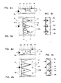
- a vortex generator essentially consists of three free-flowing triangular surfaces. These are a roof surface 10 and two side surfaces 11 and 13. In their longitudinal extent, these surfaces run at certain angles in the direction of flow.
- the two side surfaces 11 and 13 are perpendicular to the channel wall 21, it being noted that this is not mandatory.
- the side walls which consist of right-angled triangles, are fixed with their long sides on this channel wall 21, preferably gas-tight. They are oriented so that they form a joint on their narrow sides, including an arrow angle a.
- the joint is designed as a sharp connecting edge 16 and is also perpendicular to the channel wall 21 with which the side surfaces are flush.
- the two side surfaces 11, 13 including the arrow angle a are symmetrical in shape, size and orientation and are arranged on both sides of an axis of symmetry 17 (FIGS. 3b, 4b). This axis of symmetry 17 is rectified like the channel axis.
- the roof surface 10 lies with a very pointed edge 15 running transversely to the flow through the channel on the same channel wall 21 as the side walls 11, 13. Its longitudinal edges 12, 14 are flush with the longitudinal edges of the side surfaces projecting into the flow channel.
- the roof surface extends at an angle of incidence 0 to the channel wall 21. Its longitudinal edges 12, 14 form a tip 18 together with the connecting edge 16.
- the vortex generator can also be provided with a bottom surface with which it is fastened in a suitable manner to the channel wall 21.
- a floor area is not related to the mode of operation of the element.
- the connecting edge 16 of the two side surfaces 11, 13 forms the downstream edge of the vortex generator.
- the edge 15 of the roof surface 10 which runs transversely to the flow through the channel is thus the edge which is first acted upon by the channel flow.
- the vortex generator works as follows: When flowing around edges 12 and 14, the main flow is converted into a pair of opposing vortices. Their vortex axes lie in the axis of the main flow. The number of swirls and the location of the vortex breakdown (vortex breakdown), if the latter is desired at all, are determined by appropriate selection of the angle of attack 0 and the arrow angle a. With increasing angles, the vortex strength or the number of swirls is increased and the location of the vortex burst moves upstream into the area of the vortex generator itself. Depending on the application, these two angles 0 and a are predetermined by the structural conditions and by the process itself. It is then only necessary to adjust the height h of the connecting edge 16 (FIG. 3a).
- FIGS. 3a and 4a in which the channel through which flow is indicated is 20, it can be seen that the vortex generator can have different heights compared to the channel height H.
- the height h of the connecting edge 16 will be coordinated with the channel height H in such a way that the vortex generated immediately downstream of the vortex generator already reaches such a size that the full channel height H is filled, which results in a uniform speed distribution in the applied Cross section leads.
- Another criterion that can influence the ratio h / H to be selected is the pressure drop that occurs when the vortex generator flows around. It goes without saying that the pressure loss coefficient also increases with a larger ratio h / H.
- the sharp connecting edge 16 in FIG. 2 is the point which is first acted upon by the channel flow.
- the element is rotated by 180.
- the two opposite vortices have changed their sense of rotation.
- Fig. 3 it is shown how several, here 3 vortex generators are arranged side by side without gaps across the width of the flow channel 20.
- the channel 20 has a rectangular shape in this case, but this is not essential to the invention.
- FIG. 4 An embodiment variant with two full and two half vortex generators adjoining it on both sides is shown in FIG. 4.
- the elements differ in particular by their greater height h. If the angle of attack remains the same, this inevitably leads to a greater length L of the element and consequently - because of the same division - to a smaller arrow angle a.
- the vortices generated will have a lower swirl strength, but will fill the channel cross section completely within a shorter interval. If a vortex burst is intended in both cases, for example to stabilize the flow, this will take place later in the vortex generator according to FIG. 4 than in that according to FIG. 3.
- the channels shown in FIGS. 3 and 4 represent rectangular mixing chambers. It is pointed out once again that the shape of the flowed channel is not essential to the operation of the invention. Instead of the rectangle shown, the channel could also be a ring segment, i.e. the walls 21 a and 21 b would be curved. In such a case, the above statement that the side surfaces are perpendicular to the channel wall must of course be relativized. It is important that the connecting edge 16 lying on the line of symmetry 17 is perpendicular to the corresponding wall. In the case of annular walls, the connecting edge 16 would thus be aligned radially, as shown in FIG. 5.
- FIGS. 5 and 6 show in simplified form a mixing chamber with a channel 20 through which an annular flow flows.
- This annular chamber could be, for example, the annular combustion chamber of a gas turbine.
- On both channel walls 21 a and 21 b an equal number of vortex generators are lined up in the circumferential direction so that the connecting edges 16 of two opposite vortex generators lie in the same radial. If the same heights h are assumed for opposite vortex generators, FIG. 5 shows that the vortex generators on the inner channel ring 21 b have a smaller arrow a. In the longitudinal section in FIG. 6 it can be seen that this could be compensated for by a larger angle of attack 0 if swirl-like vortices in the inner and outer ring cross section are desired.
- the secondary flow in the form of cooling air has a substantially smaller mass flow than the main flow. It is introduced vertically into the main flow in the immediate area of the vortex generators.
- this injection takes place via individual bores 22a, which are made in the wall 21a a.
- the wall 21 a is the wall on which the vortex generators are arranged.
- the bores 22a are located on the line of symmetry 17 downstream behind the connecting edge 16 of each vortex generator. With this configuration, the cooling air is fed into the existing large-scale vortices.
- FIG. 4 shows an embodiment variant of a mixing chamber in which the secondary flow is also injected via wall bores 22b. These are located downstream of the vortex generators in that wall 21b on which the vortex generators are not arranged, that is to say on the wall opposite the wall 21a.
- the wall bores 22b are each made centrally between the connecting edges 16 of two adjacent vortex generators, as can be seen in FIG. 4.
- the cooling air enters the vortex in the same way as in the embodiment according to FIG. 3, but with the difference that it is no longer mixed into the vortex of a pair of vertebrae generated by the same vortex generator, but in one each Vortex of two neighboring vortex generators. Since the adjacent vortex generators are arranged without a gap and generate vortex pairs with the same direction of rotation, the injections according to FIGS. 3 and 4 have the same effect.
- FIG. 7 shows, like FIG. 5, an annular channel 20 in which an equal number of vortex generators 9 are lined up in the circumferential direction both on the outer ring wall 21 and on the inner ring wall 21b. 7, however, the connecting edges 16 of two opposite vortex generators are offset by half a division. This arrangement offers the possibility of increasing the height h of the individual element. Downstream of the vortex generators, the generated vortexes are combined with one another, which on the one hand improves the mixing quality and on the other hand leads to a longer lifespan of the vortex.
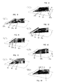
- FIGS. 8 to 14 show further possible forms of introducing the secondary flow into the main flow, which is, for example, cold cooling air to be mixed with hot combustion air or fuel gases.
- the cooling air - in addition to the already described bores 22a downstream of the vortex generators - is injected via wall bores 22c, which are located directly next to the side walls 11, 13 and in their longitudinal extent in the same wall 21a on which the Vortex generators are arranged.
- the introduction of the secondary flow through the wall bores 22c gives the generated vortices an additional impulse, which extends its service life.
- the cooling air is injected via a slot 22e or wall bores 22f, which are located directly in front of the edge 15 of the roof surface 10 running transversely to the flow channel and in its longitudinal extent in the same annular wall 21a of which the vortex generators are arranged.
- the geometry of the wall bores 22f or of the slot 22e is selected such that the cooling air is injected into the main flow at a specific injection angle and flows around the subsequent vortex generator as a protective film against the hot main flow.
- the secondary flow is introduced through means not shown through the channel wall 21 a into the hollow interior of the vortex generator.
- the cooling air is injected via wall bores 22g, which are located within the roof surface 10 directly behind the edge 15 running transversely to the flowed channel and in its longitudinal extent.
- the vortex generator is cooled more externally than internally here.
- the secondary flow emerging forms a protective layer shielding the hot main flow when it flows around the roof surface 10.
- the cooling air is injected via wall bores 22h, which are staggered within the roof surface 10 along the line of symmetry 17.
- the duct walls are particularly well protected from the hot main flow, since the cooling air is first guided around the outside of the vortex.
- the cooling air is injected via wall bores 22j, which are located in the longitudinal edges 12, 14 of the roof surface 10. This solution ensures good cooling of the vortex generators, since the cooling air exits at the extremities and thus completely flushes the inner walls of the element. The secondary flow is fed directly into the resulting vortex, which leads to defined flow conditions.
- the injection takes place via wall bores 22d, which are located in the side surfaces 11 and 13 on the one hand in the region of the longitudinal edges 12 and 14 and on the other hand in the region of the connecting edge 16.
- This variant is similar in effect to that from the bores 22a in FIG. 8 and from the bores 22j in FIG. 11.
- the mixing chamber is a combustion chamber, for example, the fuel, as a rule oil, is transferred according to FIG a central fuel lance 24 is injected, the mouth of which is located downstream of the vortex generators 9 in the area of the tip 18 thereof.
- the cooling air is injected twice in this example.
- the vortex generators 9 are designed such that recirculation zones are largely avoided. As a result, the residence time of the fuel particles in the hot zones is very short, which has a favorable effect on the minimal formation of NO x .
- the injected fuel is dragged along by the vortices and mixed with the main flow. It follows the helical course of the vertebrae and is evenly finely distributed in the chamber downstream of the vertebrae.
- the two side surfaces 11, 13 of the vortex generator 9 including the arrow angle a could also have a different length L.
- the roof surface 10 would lie with an edge 15 that runs obliquely to the channel 20 through which it flows, on the same channel wall 21 as the side walls and have a different angle of incidence 0 across the width of the vortex generator.
- Such a variant has the effect that vortices with different strengths are generated. For example, this can act on a swirl adhering to the main flow. Or, due to the different vortices, a swirl is forced on the originally swirl-free main flow downstream of the vortex generators.
- Such a configuration works well as an independent, compact burner unit. When using several such units, for example in a gas turbine ring combustor, the swirl imposed on the main flow can be exploited to improve the cross-ignition behavior of the burner configuration, e.g. to improve at partial load.
Landscapes
- Chemical & Material Sciences (AREA)
- Engineering & Computer Science (AREA)
- Chemical Kinetics & Catalysis (AREA)
- Dispersion Chemistry (AREA)
- Combustion & Propulsion (AREA)
- Mechanical Engineering (AREA)
- General Engineering & Computer Science (AREA)
- Gas Burners (AREA)
Applications Claiming Priority (2)
| Application Number | Priority Date | Filing Date | Title |
|---|---|---|---|
| CH1086/93 | 1993-04-08 | ||
| CH108693 | 1993-04-08 |
Publications (2)
| Publication Number | Publication Date |
|---|---|
| EP0619133A1 true EP0619133A1 (fr) | 1994-10-12 |
| EP0619133B1 EP0619133B1 (fr) | 1996-11-13 |
Family
ID=4202135
Family Applications (1)
| Application Number | Title | Priority Date | Filing Date |
|---|---|---|---|
| EP94103384A Expired - Lifetime EP0619133B1 (fr) | 1993-04-08 | 1994-03-07 | Chambre de mélanges |
Country Status (4)
| Country | Link |
|---|---|
| US (1) | US5518311A (fr) |
| EP (1) | EP0619133B1 (fr) |
| JP (1) | JP3527279B2 (fr) |
| DE (1) | DE59401018D1 (fr) |
Cited By (15)
| Publication number | Priority date | Publication date | Assignee | Title |
|---|---|---|---|---|
| DE19510744A1 (de) * | 1995-03-24 | 1996-09-26 | Abb Management Ag | Brennkammer mit Zweistufenverbrennung |
| DE19520291A1 (de) * | 1995-06-02 | 1996-12-05 | Abb Management Ag | Brennkammer |
| EP0718561A3 (fr) * | 1994-12-24 | 1997-04-23 | Abb Management Ag | Brûleur |
| DE19543701A1 (de) * | 1995-11-23 | 1997-05-28 | Abb Research Ltd | Vormischbrenner |
| DE19544816A1 (de) * | 1995-12-01 | 1997-06-05 | Abb Research Ltd | Mischvorrichtung |
| EP0795685A1 (fr) | 1996-03-14 | 1997-09-17 | Asea Brown Boveri Ag | Turbine à gaz multi-étagée avec refroidissement par vapeur et réinjection en chambre de combustion |
| US5689948A (en) * | 1995-03-07 | 1997-11-25 | Asea Brown Boveri Ag | Method of operating a reheat power plant with steam injection |
| EP0789187A3 (fr) * | 1995-09-30 | 1998-10-14 | Abb Research Ltd. | Procédé et dispositif pour la combustion des combustibles |
| US5884470A (en) * | 1996-04-22 | 1999-03-23 | Asea Brown Boveri Ag | Method of operating a combined-cycle plant |
| EP0978635A1 (fr) | 1998-08-05 | 2000-02-09 | Asea Brown Boveri AG | Procédé pour refroidir les structures thermiquement chargées d'une centrale thermique |
| US6572366B2 (en) | 2001-06-09 | 2003-06-03 | Alstom (Switzerland) Ltd | Burner system |
| WO2010011381A1 (fr) * | 2008-06-26 | 2010-01-28 | General Electric Company | Tuyère d'échappement à volets duplex |
| EP2230455A1 (fr) * | 2009-03-16 | 2010-09-22 | Alstom Technology Ltd | Brûleur pour une turbine à gaz et procédé de refroidissement local d'un flux de gaz chauds passant par un brûleur |
| WO2014209549A3 (fr) * | 2013-06-27 | 2015-02-26 | Siemens Aktiengesellschaft | Appareil de réduction d'un gradient de température de fluide de flux principal en aval d'un profilé dans un moteur de turbine à gaz |
| CN108375082A (zh) * | 2017-01-31 | 2018-08-07 | 安萨尔多能源瑞士股份公司 | 用于燃气涡轮机燃烧器的波瓣状喷射器 |
Families Citing this family (32)
| Publication number | Priority date | Publication date | Assignee | Title |
|---|---|---|---|---|
| CH687832A5 (de) * | 1993-04-08 | 1997-02-28 | Asea Brown Boveri | Brennstoffzufuehreinrichtung fuer Brennkammer. |
| WO1995026226A1 (fr) * | 1994-03-25 | 1995-10-05 | Siemens Aktiengesellschaft | Systeme combine d'amenee et de melange |
| DE19700462C2 (de) * | 1997-01-09 | 1999-07-01 | Guenther Schwald | Statischer Mischer |
| DE19820992C2 (de) * | 1998-05-11 | 2003-01-09 | Bbp Environment Gmbh | Vorrichtung zur Durchmischung eines einen Kanal durchströmenden Gasstromes und Verfahren unter Verwendung der Vorrichtung |
| FI114030B (fi) * | 1999-10-12 | 2004-07-30 | Metso Paper Inc | Menetelmä ja sovitelma paperinvalmistuksen massakomponenttien sekoittamiseksi |
| ES2190920T3 (es) * | 2000-06-19 | 2003-09-01 | Balcke Duerr Gmbh | Mezclador para mezcla de gases y otros liquidos newtonianos. |
| US6886973B2 (en) * | 2001-01-03 | 2005-05-03 | Basic Resources, Inc. | Gas stream vortex mixing system |
| US6637668B2 (en) * | 2001-10-24 | 2003-10-28 | Magarl, Llc | Thermostatic control valve with fluid mixing |
| DE10330023A1 (de) * | 2002-07-20 | 2004-02-05 | Alstom (Switzerland) Ltd. | Wirbelgenerator mit kontrollierter Nachlaufströmung |
| CN1204945C (zh) * | 2003-09-05 | 2005-06-08 | 刘兆彦 | 一种管、筒或塔内构件立交盘 |
| US7383850B2 (en) * | 2005-01-18 | 2008-06-10 | Peerless Mfg. Co. | Reagent injection grid |
| US7458520B2 (en) * | 2005-04-19 | 2008-12-02 | Masco Corporation Of Indiana | Electronic proportioning valve |
| US7448553B2 (en) | 2005-04-19 | 2008-11-11 | Masco Corporation Of Indiana | Fluid mixer |
| US7475827B2 (en) | 2005-04-19 | 2009-01-13 | Masco Corporation Of Indiana | Fluid mixer |
| US7584898B2 (en) | 2005-07-01 | 2009-09-08 | Masco Corporation Of Indiana | Manual override for electronic proportioning valve |
| US20080060361A1 (en) * | 2006-09-07 | 2008-03-13 | Pratt & Whitney Rocketdyne, Inc. | Multi-height ramp injector scramjet combustor |
| US20080237044A1 (en) * | 2007-03-28 | 2008-10-02 | The Charles Stark Draper Laboratory, Inc. | Method and apparatus for concentrating molecules |
| WO2008130618A1 (fr) | 2007-04-19 | 2008-10-30 | The Charles Stark Draper Laboratory, Inc. | Procédé et appareil pour séparer des particules, cellules, molécules et matières particulaires |
| US7837379B2 (en) * | 2007-08-13 | 2010-11-23 | The Charles Stark Draper Laboratory, Inc. | Devices for producing a continuously flowing concentration gradient in laminar flow |
| CN102792022B (zh) * | 2009-09-18 | 2016-02-24 | 麻省理工学院 | 会聚的太阳能电力系统 |
| JP2011102669A (ja) * | 2009-11-10 | 2011-05-26 | Mitsubishi Heavy Ind Ltd | ガスタービン燃焼器及びガスタービン |
| WO2011151323A2 (fr) | 2010-06-01 | 2011-12-08 | Esg Mbh | Canal à surface de guidage d'écoulement |
| US8690536B2 (en) * | 2010-09-28 | 2014-04-08 | Siemens Energy, Inc. | Turbine blade tip with vortex generators |
| US9435537B2 (en) * | 2010-11-30 | 2016-09-06 | General Electric Company | System and method for premixer wake and vortex filling for enhanced flame-holding resistance |
| US20130047978A1 (en) * | 2011-08-31 | 2013-02-28 | Massachusetts Institute Of Technology | Vortex-induced cleaning of surfaces |
| US20140123653A1 (en) * | 2012-11-08 | 2014-05-08 | General Electric Company | Enhancement for fuel injector |
| EP2775107A1 (fr) | 2013-03-06 | 2014-09-10 | Alstom Technology Ltd | Procédé pour démarrer une centrale électrique à cycle combiné |
| US9358557B2 (en) * | 2013-12-20 | 2016-06-07 | Young Living Essential Oils, Lc | Liquid diffuser |
| MA39834A (fr) | 2014-05-13 | 2015-11-19 | Massachusetts Inst Technology | Réflecteur cylindro-parabolique de faible coût conçu pour une énergie solaire concentrée |
| US9968929B2 (en) * | 2015-10-27 | 2018-05-15 | Apex Biotechnology Corp. | Reaction cassette and assay device |
| US11067277B2 (en) * | 2016-10-07 | 2021-07-20 | General Electric Company | Component assembly for a gas turbine engine |
| CN115487698B (zh) * | 2022-09-01 | 2024-05-03 | 同济大学 | 一种土壤中污染物高压涡流高效分离方法 |
Citations (7)
| Publication number | Priority date | Publication date | Assignee | Title |
|---|---|---|---|---|
| CH581493A5 (en) * | 1974-06-24 | 1976-11-15 | Escher Wyss Ag | Static mixer for in line mixing - having sudden expansion with secondary fluid injection just prior to it |
| FR2404458A1 (fr) * | 1977-09-28 | 1979-04-27 | Mahler Arnold | Dispositif d'homogeneisation d'un courant fluidique charge de particules |
| AT360737B (de) * | 1979-05-03 | 1981-01-26 | Ivar Wolff Ges M B H Dr | Vorrichtung zum zumischen von zuschlagstoffen in einen materialstrom |
| DE2934087A1 (de) * | 1978-10-07 | 1981-03-12 | Ruhrkohle Ag, 4300 Essen | Austragsduese |
| GB2087249A (en) * | 1980-11-15 | 1982-05-26 | Balcke Duerr Ag | Method and apparatus for the mixing of at least two fluid flows |
| US4899772A (en) * | 1988-10-20 | 1990-02-13 | Rockwell International Corporation | Mixing aids for supersonic flows |
| WO1992011642A2 (fr) * | 1990-12-21 | 1992-07-09 | Siemens Aktiengesellschaft | Dispositif de confinement d'une installation pour reacteurs nucleaires et procede de refroidissement de secours en cas de fusion du c×ur |
Family Cites Families (10)
| Publication number | Priority date | Publication date | Assignee | Title |
|---|---|---|---|---|
| US1022493A (en) * | 1910-08-31 | 1912-04-09 | Curtis C Meigs | Apparatus for making sulfuric acid. |
| US1454196A (en) * | 1921-07-16 | 1923-05-08 | Trood Samuel | Device for producing and utilizing combustible mixture |
| US1466006A (en) * | 1922-09-14 | 1923-08-28 | Trood Samuel | Apparatus for producing and utilizing combustible mixture |
| US3051452A (en) * | 1957-11-29 | 1962-08-28 | American Enka Corp | Process and apparatus for mixing |
| US3239197A (en) * | 1960-05-31 | 1966-03-08 | Dow Chemical Co | Interfacial surface generator |
| US3404869A (en) * | 1966-07-18 | 1968-10-08 | Dow Chemical Co | Interfacial surface generator |
| US3671208A (en) * | 1970-10-09 | 1972-06-20 | Wayne G Medsker | Fluid mixing apparatus |
| US4164375A (en) * | 1976-05-21 | 1979-08-14 | E. T. Oakes Limited | In-line mixer |
| CA1129303A (fr) * | 1978-07-19 | 1982-08-10 | Figgie International Inc. | Respirateur a pression et a demande avec vanne automatique |
| DE3520772A1 (de) | 1985-06-10 | 1986-12-11 | INTERATOM GmbH, 5060 Bergisch Gladbach | Mischvorrichtung |
-
1994
- 1994-03-07 DE DE59401018T patent/DE59401018D1/de not_active Expired - Lifetime
- 1994-03-07 EP EP94103384A patent/EP0619133B1/fr not_active Expired - Lifetime
- 1994-04-08 US US08/225,397 patent/US5518311A/en not_active Expired - Lifetime
- 1994-04-08 JP JP07112394A patent/JP3527279B2/ja not_active Expired - Lifetime
Patent Citations (7)
| Publication number | Priority date | Publication date | Assignee | Title |
|---|---|---|---|---|
| CH581493A5 (en) * | 1974-06-24 | 1976-11-15 | Escher Wyss Ag | Static mixer for in line mixing - having sudden expansion with secondary fluid injection just prior to it |
| FR2404458A1 (fr) * | 1977-09-28 | 1979-04-27 | Mahler Arnold | Dispositif d'homogeneisation d'un courant fluidique charge de particules |
| DE2934087A1 (de) * | 1978-10-07 | 1981-03-12 | Ruhrkohle Ag, 4300 Essen | Austragsduese |
| AT360737B (de) * | 1979-05-03 | 1981-01-26 | Ivar Wolff Ges M B H Dr | Vorrichtung zum zumischen von zuschlagstoffen in einen materialstrom |
| GB2087249A (en) * | 1980-11-15 | 1982-05-26 | Balcke Duerr Ag | Method and apparatus for the mixing of at least two fluid flows |
| US4899772A (en) * | 1988-10-20 | 1990-02-13 | Rockwell International Corporation | Mixing aids for supersonic flows |
| WO1992011642A2 (fr) * | 1990-12-21 | 1992-07-09 | Siemens Aktiengesellschaft | Dispositif de confinement d'une installation pour reacteurs nucleaires et procede de refroidissement de secours en cas de fusion du c×ur |
Cited By (24)
| Publication number | Priority date | Publication date | Assignee | Title |
|---|---|---|---|---|
| EP0718561A3 (fr) * | 1994-12-24 | 1997-04-23 | Abb Management Ag | Brûleur |
| US5689948A (en) * | 1995-03-07 | 1997-11-25 | Asea Brown Boveri Ag | Method of operating a reheat power plant with steam injection |
| US5829967A (en) * | 1995-03-24 | 1998-11-03 | Asea Brown Boveri Ag | Combustion chamber with two-stage combustion |
| DE19510744A1 (de) * | 1995-03-24 | 1996-09-26 | Abb Management Ag | Brennkammer mit Zweistufenverbrennung |
| DE19520291A1 (de) * | 1995-06-02 | 1996-12-05 | Abb Management Ag | Brennkammer |
| US5735126A (en) * | 1995-06-02 | 1998-04-07 | Asea Brown Boveri Ag | Combustion chamber |
| EP0789187A3 (fr) * | 1995-09-30 | 1998-10-14 | Abb Research Ltd. | Procédé et dispositif pour la combustion des combustibles |
| EP0775869A3 (fr) * | 1995-11-23 | 1998-03-11 | Abb Research Ltd. | Brûleur à prémélange |
| US5791892A (en) * | 1995-11-23 | 1998-08-11 | Abb Research Ltd. | Premix burner |
| DE19543701A1 (de) * | 1995-11-23 | 1997-05-28 | Abb Research Ltd | Vormischbrenner |
| DE19544816A1 (de) * | 1995-12-01 | 1997-06-05 | Abb Research Ltd | Mischvorrichtung |
| US5803602A (en) * | 1995-12-01 | 1998-09-08 | Abb Research Ltd. | Fluid mixing device with vortex generators |
| EP0795685A1 (fr) | 1996-03-14 | 1997-09-17 | Asea Brown Boveri Ag | Turbine à gaz multi-étagée avec refroidissement par vapeur et réinjection en chambre de combustion |
| US5884470A (en) * | 1996-04-22 | 1999-03-23 | Asea Brown Boveri Ag | Method of operating a combined-cycle plant |
| EP0978635A1 (fr) | 1998-08-05 | 2000-02-09 | Asea Brown Boveri AG | Procédé pour refroidir les structures thermiquement chargées d'une centrale thermique |
| US6572366B2 (en) | 2001-06-09 | 2003-06-03 | Alstom (Switzerland) Ltd | Burner system |
| WO2010011381A1 (fr) * | 2008-06-26 | 2010-01-28 | General Electric Company | Tuyère d'échappement à volets duplex |
| GB2474377A (en) * | 2008-06-26 | 2011-04-13 | Gen Electric | Duplex tab exhaust nozzle |
| US8087250B2 (en) | 2008-06-26 | 2012-01-03 | General Electric Company | Duplex tab exhaust nozzle |
| GB2474377B (en) * | 2008-06-26 | 2012-02-29 | Gen Electric | Duplex tab exhaust nozzle |
| EP2230455A1 (fr) * | 2009-03-16 | 2010-09-22 | Alstom Technology Ltd | Brûleur pour une turbine à gaz et procédé de refroidissement local d'un flux de gaz chauds passant par un brûleur |
| US8850788B2 (en) | 2009-03-16 | 2014-10-07 | Alstom Technology Ltd | Burner including non-uniformly cooled tetrahedron vortex generators and method for cooling |
| WO2014209549A3 (fr) * | 2013-06-27 | 2015-02-26 | Siemens Aktiengesellschaft | Appareil de réduction d'un gradient de température de fluide de flux principal en aval d'un profilé dans un moteur de turbine à gaz |
| CN108375082A (zh) * | 2017-01-31 | 2018-08-07 | 安萨尔多能源瑞士股份公司 | 用于燃气涡轮机燃烧器的波瓣状喷射器 |
Also Published As
| Publication number | Publication date |
|---|---|
| JP3527279B2 (ja) | 2004-05-17 |
| DE59401018D1 (de) | 1996-12-19 |
| EP0619133B1 (fr) | 1996-11-13 |
| JPH06307640A (ja) | 1994-11-01 |
| US5518311A (en) | 1996-05-21 |
Similar Documents
| Publication | Publication Date | Title |
|---|---|---|
| EP0619133B1 (fr) | Chambre de mélanges | |
| EP0623786B1 (fr) | Chambre de combustion | |
| EP0619457B1 (fr) | Brûleur à prémélange | |
| EP0620403B1 (fr) | Dispositif de mélange et de stabilisation de la flamme dans une chambre de combustion avec mélange préalable du combustible. | |
| EP0619456B1 (fr) | Système d'alimentation en carburant pour chambre de combustion | |
| DE3131070C2 (fr) | ||
| EP1382379B1 (fr) | Procédé pour le contrôle de fluide en aval d'un générateur de tourbillons | |
| EP0619134B1 (fr) | Chambre de mélange | |
| EP0675322A2 (fr) | Brûleur à prémélange | |
| DE1926295C3 (de) | Flammrohr für eine Ringbrennkammer | |
| EP1681090A1 (fr) | Dispositif et procédé de mélange d'un courant de fluide dans un conduit | |
| EP1986788A1 (fr) | Tuyere a deux matieres dotee de tuyeres d'air secondaire disposees en cercle | |
| DE10019759C2 (de) | Statisches Mischsystem | |
| CH581493A5 (en) | Static mixer for in line mixing - having sudden expansion with secondary fluid injection just prior to it | |
| EP0807213B1 (fr) | Corps de guidage de l'ecoulement pour chambres de combustion de turbines a gaz | |
| DE19544816A1 (de) | Mischvorrichtung | |
| DE69521908T2 (de) | Statische luftmischungsvorrichtung | |
| DE2842047C2 (de) | Vorrichtung zur Verteilung von Kraftstoff in einem Nachverbrennungs-Kanal, insbesondere eines Strahltriebwerks | |
| DE69931519T2 (de) | Verfahren und vorrichtung zur mischung von fliessenden gasen und pulverförmigem material | |
| DE1929370A1 (de) | Verbrennungseinrichtung | |
| DE3021606A1 (de) | Vorrichtung zum erzeugen von kleinblasigem schaum | |
| DE4409565A1 (de) | Gasturbinenanlage mit einer Druckwellenmaschine | |
| CH688868A5 (de) | Durchstroemter Kanal mit einem Wirbelgenerator | |
| DE29521184U1 (de) | Vorrichtung in einem ein Primärfluid führenden Kanal | |
| DE4142413A1 (de) | Brennkammergehaeuse einer gasturbine |
Legal Events
| Date | Code | Title | Description |
|---|---|---|---|
| PUAI | Public reference made under article 153(3) epc to a published international application that has entered the european phase |
Free format text: ORIGINAL CODE: 0009012 |
|
| AK | Designated contracting states |
Kind code of ref document: A1 Designated state(s): DE FR GB |
|
| K1C1 | Correction of patent application (title page) published |
Effective date: 19941012 |
|
| 17P | Request for examination filed |
Effective date: 19950307 |
|
| RIN1 | Information on inventor provided before grant (corrected) |
Inventor name: EROGLU, ADNAN, DR. Inventor name: CHYOU, YAU-PIN, DR. Inventor name: BEECK, ALEXANDER, DR. Inventor name: ALTHAUS, ROLF,DR. |
|
| GRAG | Despatch of communication of intention to grant |
Free format text: ORIGINAL CODE: EPIDOS AGRA |
|
| GRAG | Despatch of communication of intention to grant |
Free format text: ORIGINAL CODE: EPIDOS AGRA |
|
| GRAG | Despatch of communication of intention to grant |
Free format text: ORIGINAL CODE: EPIDOS AGRA |
|
| 17Q | First examination report despatched |
Effective date: 19960115 |
|
| GRAH | Despatch of communication of intention to grant a patent |
Free format text: ORIGINAL CODE: EPIDOS IGRA |
|
| GRAH | Despatch of communication of intention to grant a patent |
Free format text: ORIGINAL CODE: EPIDOS IGRA |
|
| GRAA | (expected) grant |
Free format text: ORIGINAL CODE: 0009210 |
|
| AK | Designated contracting states |
Kind code of ref document: B1 Designated state(s): DE FR GB |
|
| REF | Corresponds to: |
Ref document number: 59401018 Country of ref document: DE Date of ref document: 19961219 |
|
| GBT | Gb: translation of ep patent filed (gb section 77(6)(a)/1977) |
Effective date: 19970205 |
|
| ET | Fr: translation filed | ||
| PLBE | No opposition filed within time limit |
Free format text: ORIGINAL CODE: 0009261 |
|
| STAA | Information on the status of an ep patent application or granted ep patent |
Free format text: STATUS: NO OPPOSITION FILED WITHIN TIME LIMIT |
|
| 26N | No opposition filed | ||
| REG | Reference to a national code |
Ref country code: GB Ref legal event code: IF02 |
|
| REG | Reference to a national code |
Ref country code: FR Ref legal event code: TP |
|
| REG | Reference to a national code |
Ref country code: GB Ref legal event code: 732E |
|
| REG | Reference to a national code |
Ref country code: DE Ref legal event code: R082 Ref document number: 59401018 Country of ref document: DE Representative=s name: ROESLER, UWE, DIPL.-PHYS.UNIV., DE Effective date: 20120621 Ref country code: DE Ref legal event code: R081 Ref document number: 59401018 Country of ref document: DE Owner name: ALSTOM TECHNOLOGY LTD., CH Free format text: FORMER OWNER: ALSTOM, PARIS, FR Effective date: 20120621 |
|
| REG | Reference to a national code |
Ref country code: GB Ref legal event code: 732E Free format text: REGISTERED BETWEEN 20120802 AND 20120808 |
|
| REG | Reference to a national code |
Ref country code: FR Ref legal event code: TP Owner name: ALSTOM TECHNOLOGY LTD., CH Effective date: 20121008 |
|
| PGFP | Annual fee paid to national office [announced via postgrant information from national office to epo] |
Ref country code: GB Payment date: 20130225 Year of fee payment: 20 Ref country code: FR Payment date: 20130315 Year of fee payment: 20 |
|
| PGFP | Annual fee paid to national office [announced via postgrant information from national office to epo] |
Ref country code: DE Payment date: 20130328 Year of fee payment: 20 |
|
| REG | Reference to a national code |
Ref country code: DE Ref legal event code: R071 Ref document number: 59401018 Country of ref document: DE |
|
| REG | Reference to a national code |
Ref country code: GB Ref legal event code: PE20 Expiry date: 20140306 |
|
| PG25 | Lapsed in a contracting state [announced via postgrant information from national office to epo] |
Ref country code: GB Free format text: LAPSE BECAUSE OF EXPIRATION OF PROTECTION Effective date: 20140306 Ref country code: DE Free format text: LAPSE BECAUSE OF EXPIRATION OF PROTECTION Effective date: 20140308 |