EP0619136A1 - Rührerblatt und Rührverfahren - Google Patents
Rührerblatt und Rührverfahren Download PDFInfo
- Publication number
- EP0619136A1 EP0619136A1 EP94104601A EP94104601A EP0619136A1 EP 0619136 A1 EP0619136 A1 EP 0619136A1 EP 94104601 A EP94104601 A EP 94104601A EP 94104601 A EP94104601 A EP 94104601A EP 0619136 A1 EP0619136 A1 EP 0619136A1
- Authority
- EP
- European Patent Office
- Prior art keywords
- liquid
- transporting means
- agitator
- agitator blade
- liquid transporting
- Prior art date
- Legal status (The legal status is an assumption and is not a legal conclusion. Google has not performed a legal analysis and makes no representation as to the accuracy of the status listed.)
- Granted
Links
- 238000000034 method Methods 0.000 title claims abstract description 24
- 238000013019 agitation Methods 0.000 title claims description 58
- 239000007788 liquid Substances 0.000 claims abstract description 212
- 230000005484 gravity Effects 0.000 claims abstract description 12
- 238000002156 mixing Methods 0.000 claims description 10
- 239000007787 solid Substances 0.000 claims description 8
- 239000000725 suspension Substances 0.000 claims description 6
- 239000006260 foam Substances 0.000 description 17
- 238000010438 heat treatment Methods 0.000 description 10
- 239000002518 antifoaming agent Substances 0.000 description 9
- 238000001816 cooling Methods 0.000 description 9
- 230000002093 peripheral effect Effects 0.000 description 9
- 239000007921 spray Substances 0.000 description 8
- 238000012258 culturing Methods 0.000 description 4
- 238000000855 fermentation Methods 0.000 description 4
- 230000004151 fermentation Effects 0.000 description 4
- 0 C*1CCCC1 Chemical compound C*1CCCC1 0.000 description 3
- 229910000831 Steel Inorganic materials 0.000 description 3
- 239000012530 fluid Substances 0.000 description 3
- 239000000203 mixture Substances 0.000 description 3
- 239000010959 steel Substances 0.000 description 3
- 239000002699 waste material Substances 0.000 description 3
- 238000004140 cleaning Methods 0.000 description 2
- 239000013530 defoamer Substances 0.000 description 2
- 238000005187 foaming Methods 0.000 description 2
- 239000012535 impurity Substances 0.000 description 2
- 229920001296 polysiloxane Polymers 0.000 description 2
- 238000003466 welding Methods 0.000 description 2
- 230000002411 adverse Effects 0.000 description 1
- 238000005452 bending Methods 0.000 description 1
- 238000011109 contamination Methods 0.000 description 1
- 230000007547 defect Effects 0.000 description 1
- 238000007599 discharging Methods 0.000 description 1
- 238000001704 evaporation Methods 0.000 description 1
- 230000008020 evaporation Effects 0.000 description 1
- 244000005700 microbiome Species 0.000 description 1
- 238000012986 modification Methods 0.000 description 1
- 230000004048 modification Effects 0.000 description 1
- 230000035515 penetration Effects 0.000 description 1
- 239000002994 raw material Substances 0.000 description 1
- 230000002040 relaxant effect Effects 0.000 description 1
- 238000011160 research Methods 0.000 description 1
- 230000000630 rising effect Effects 0.000 description 1
- 238000007789 sealing Methods 0.000 description 1
- 238000010008 shearing Methods 0.000 description 1
- 239000000126 substance Substances 0.000 description 1
Images




Classifications
-
- B—PERFORMING OPERATIONS; TRANSPORTING
- B01—PHYSICAL OR CHEMICAL PROCESSES OR APPARATUS IN GENERAL
- B01F—MIXING, e.g. DISSOLVING, EMULSIFYING OR DISPERSING
- B01F23/00—Mixing according to the phases to be mixed, e.g. dispersing or emulsifying
- B01F23/20—Mixing gases with liquids
- B01F23/23—Mixing gases with liquids by introducing gases into liquid media, e.g. for producing aerated liquids
- B01F23/234—Surface aerating
- B01F23/2342—Surface aerating with stirrers near to the liquid surface, e.g. partially immersed, for spraying the liquid in the gas or for sucking gas into the liquid, e.g. using stirrers rotating around a horizontal axis or using centrifugal force
- B01F23/23421—Surface aerating with stirrers near to the liquid surface, e.g. partially immersed, for spraying the liquid in the gas or for sucking gas into the liquid, e.g. using stirrers rotating around a horizontal axis or using centrifugal force the stirrers rotating about a vertical axis
- B01F23/234211—Stirrers thereof
-
- B—PERFORMING OPERATIONS; TRANSPORTING
- B01—PHYSICAL OR CHEMICAL PROCESSES OR APPARATUS IN GENERAL
- B01F—MIXING, e.g. DISSOLVING, EMULSIFYING OR DISPERSING
- B01F23/00—Mixing according to the phases to be mixed, e.g. dispersing or emulsifying
- B01F23/20—Mixing gases with liquids
- B01F23/23—Mixing gases with liquids by introducing gases into liquid media, e.g. for producing aerated liquids
- B01F23/234—Surface aerating
- B01F23/2342—Surface aerating with stirrers near to the liquid surface, e.g. partially immersed, for spraying the liquid in the gas or for sucking gas into the liquid, e.g. using stirrers rotating around a horizontal axis or using centrifugal force
- B01F23/23421—Surface aerating with stirrers near to the liquid surface, e.g. partially immersed, for spraying the liquid in the gas or for sucking gas into the liquid, e.g. using stirrers rotating around a horizontal axis or using centrifugal force the stirrers rotating about a vertical axis
-
- B—PERFORMING OPERATIONS; TRANSPORTING
- B01—PHYSICAL OR CHEMICAL PROCESSES OR APPARATUS IN GENERAL
- B01F—MIXING, e.g. DISSOLVING, EMULSIFYING OR DISPERSING
- B01F27/00—Mixers with rotary stirring devices in fixed receptacles; Kneaders
- B01F27/05—Stirrers
- B01F27/11—Stirrers characterised by the configuration of the stirrers
- B01F27/15—Stirrers with tubes for guiding the material
Definitions
- the present invention relates to an agitator blade and a method of agitation using said agitator blade, and more particularly to an agitator blade and an agitation method, both being suitably applicable for extinguishing foam from foamable liquids, cleaning of inner wall surface of agitating tank, effective utilization of heating surface area, or mixing liquids of different specific gravities or liquids of different solid contents.
- the fermenting liquids and culturing liquids are very prone to foam. Agitation foam causes foam during the process, and the foam often impairs operability of the process.
- anti-foaming agents such as silicone is generally adopted.
- the use of such anti-foaming agents not only requires significant cost, but also poses a risk adversely affecting the fermentation and culturing processes, because these anti-foaming agents are, in themselves, foreign substances to the liquids.
- the anti-foaming agents are often included as impurities in the product until the product is degraded. It requires additional labor to remove them from the product. Furthermore, they contaminate waste liquid and impede a treatment of waste liquid. Accordingly, addition of anti-foaming agents is not desirable and should be controlled as little as possible.
- the inner wall surface of agitating tank is contaminated owing to microorganisms or solid raw materials or products deposited thereon. This often causes decrease of reaction yield or reduction of heat transfer coefficient.
- the liquid in the agitation tank reduces, for example, by evaporation and liquid level lowers with lapse of time. As a result, the heat transfer area of the heating and cooling apparatuses cannot be effectively utilized.
- the inventors achieved the present invention after conducting elaborate researches regarding agitation blades and methods of agitation, which, overcoming by mere mechanical agitation the drawbacks in conventional defoaming by agitation and the drawbacks such as contamination and reduction in heat transfer area of the inner wall surface of agitation tank and the surface of heating and cooling apparatuses and low mixing rate in mixing liquids of different specific gravity and suspensions, can efficiently and thoroughly extinguish foam and can clean the inner wall surface of agitation tank and the surface of heating and cooling apparatuses, can inhibit the reduction of heat transfer area of the inner wall surface of agitation tank and heating and cooling apparatuses, and can efficiently mix liquids of different specific gravities and suspensions.
- the first invention lies in an agitating blade which is characterized by one or more liquid transporting means arranged on a mounting frame attached to an agitator shaft, the both ends of each of said liquid transporting means being opened to have an upper opening and a lower opening, respectively.
- the second invention is an agitating method.
- the method is characterized by arranging one or more liquid transporting means on a mounting frame attached to an agitator shaft, forming upper openings and lower openings at the both ends of said liquid transporting means of the agitator blade, locating the upper openings and the lower openings in the space above the liquid surface and in the liquid in an agitation tank, respectively, and rotating said agitator blade to agitate the liquid and simultaneously discharge the liquid in the tank from the upper openings into the space above the surface of the liquid in the tank through said liquid transporting means.
- the third invention is a method of agitating and mixing liquids.
- the method is characterized by arranging one or more liquid transporting means on a mounting frame attached to an agitator shaft, forming upper openings and lower openings at the both ends of each of said liquid transporting means of an agitator blade, interconnecting the upper part and the lower part of the liquid in an agitation tank by said liquid transporting means, and rotating the agitator blade to discharge one of the liquids from openings of the liquid transporting means into another liquid, thereby to mix the upper liquid and the lower liquid.
- upper and lower mean “a position near the bottom of liquid” and “a position far from the bottom”, respectively.
- the mounting frame is designed to mount the agitator blade on an agitator shaft and to hold one or more liquid transporting means.
- the mounting frame may be formed of either rods, square bars, shaped steels, plates provided with many perforations (sometimes referred to as perforated plates hereinafter) or non-perforated plates. These non-perforated plates and perforated plates are preferably provided at the agitator shaft so as to reduce fluid resistance as much as possible when rotated in liquid.
- the non-perforated plates is preferably those which have a narrow width when they are used in longitudinal state (in the state perpendicular to rotating plane of the agitator blade).
- These rods, square bars, shaped steels, perforated plates and non-perforated plates are positioned approximately on the diameter line of the rotating plane.
- the number of these rods, square bars, shaped steels, perforated plates and non-perforated plates may be one or more. When plural numbers are used, each member may be positioned either on the same rotating plane or on the plane differing each other.
- These mounting frames are arranged approximately perpendicular to the agitator shaft.
- the liquid transporting means may be ones through which liquid can move and are usually tube bodies, but may be gutter bodies, plate bodies and bottomless and hollow truncated cone bodies.
- the tube body can be a straight tube as a whole, but may have an upper portion formed straight and a lower portion formed bent or may be nearly S shaped. It is preferred in practice that the bent portion be fixed approximately perpendicular to the rotating axis or slightly inclined downward with respect thereto. Furthermore, the upper strainght portion may be preferably directed to obliquely upper or lower direction or to side wall of the agitation tank, or may be bent to optional directions such as toward the rotating axis.
- the lower bent portion of tube body may be formed either by bending the lower portion or by connecting a separate tube to the end of the straight portion, for example, by welding or screwing.
- the bent portion of the tube body is preferably formed, on the rotating plane containing the junction point between the bent and straight portions, at an angle of substantially 0-90 ° to radial direction of the rotating plane, namely, on the radius of the rotating plane or along a circle drawn with a radius equal to the distance from the rotating axis to said junction point, or along the tangent line to the above circle.
- the whole tube body can be curved along an arc of a circle having a radius nearly equal to the distance from the agitation shaft to the position at which the tube body is fixed.
- liquid trnasport means in the form of gutter body and plate body.
- the upper and lower ends of the tube body are opened in the agitation tank to form an upper opening and a lower opening, respectively.
- the fellow upper openings and the fellow lower openings may respectively be located either on substantially the same rotating plane or on different planes.
- Shape of the upper opening of the tube body is unlimited and usually circular form such as circle, ellipse or oval or polygon such as triangle, square, rectangle, rhombus, hexagon or octagon.
- the upper opening can be covered with a perforated plate and, if necessary, this upper opening can be in the form of funnel and thus, the tube body can be shower spray type tube body.
- the spray type tube body can also be formed by using a blind tube with no opening as the upper opening portion and perforating many holes therethrough.
- Shape of the lower opening of the tube body and that of section of the tube body are also unlimited and usually circular form such as circle, ellipse or oval or polygon such as triangle, square, rectangle, rhombus, hexagon or octagon.
- the gutter body as liquid transporting means corresponds to the above-mentioned tube body from which the upper part is cut away, and shapes of section and upper and lower openings are, for example, half circle, half ellipse, half oval, U-shape and V-shape, and polygon such as square or rectangle from which one side is omitted.
- the plate body as liquid transporting means has a whole side shape such as linear shape or long S shape and has a whole planar shape such as long trapezoid or rectangle or either of these shapes curved at a small curveture.
- a whole side shape such as linear shape or long S shape and has a whole planar shape such as long trapezoid or rectangle or either of these shapes curved at a small curveture.
- One of the both ends of this plate body which is allowed to go ahead may be upwardly or downwardly twisted so that the outer periphery side (in use of the agitator) is directed to the mounting frame.
- the upper end and the lower end of the plate body as the liquid transporting means correspond to the upper opening and the lower opening, respectively.
- the shape of upper opening and that of lower opening of the liquid transporting means such as tube body, gutter body and plate body (sometimes referred to as long and narrow liquid transporting means hereiafter) may be the same or different.
- One of the both openings of the long and narrow liquid transporting means which is allowed to go advance at the time of agitation may be thin and sharp in its end to reduce fluid resistance.
- the area of the upper opening and the lower opening of the long and narrow liquid transporting means may be either substantially equal or different, the latter being preferred for practical use. In the latter case, the ratio of the both openings is optionally selected depending on the kind of the liquid, purpose of agitation and operational conditions.
- either of the openings can be an opening which scoops up the liquid (sometimes referred to as intake opening hereiafter) or an opening which discharges the liquid (sometimes referred to as discharge opening hereinafter), but for practical use the larger opening is normally employed as the intake opening.
- the area of opening is total area of the holes.
- the length of the line and that of the curve correspond to the area of the openings.
- the upper opening is preferably in the form substantially parallel to the mounting frame, namely, flat shape substantially parallel to the rotating plane, for instance, long rectangular, rhombus, oval or ellipse.
- the upper opening is not covered with a perforated plate and completely opened.
- the long and narrow liquid transporting means are arranged either perpendicular or inclined to the mounting frame. In operation, the liquid transporting means become almost parallel to the rotating axis in the former case, while inclined in the latter case. In practice, the inclined arrangement is preferred.
- the long and narrow liquid transporting means are usually arranged so that the intake opening is allowed to go ahead in rotation of the agitator.
- the angles of inclination may be the same or different.
- the angle of inclination of the long and narrow liquid transporting means may vary depending on the viscosity of the liquid, the size of the long and narrow liquid transporting means, etc. and is not able to be generally fixed to a given angle. The range from about 15-75 ° is preferable in practice.
- a plurality of long and narrow liquid transporting means arranged on the mounting frame are generally same in size, shape and type, but may be different.
- the long and narrow liquid transporting means can be rotatably attached to the mounting frame so as to be able to freely adjust the angle to the rotating axis and the angle to the radial direction of rotating plane.
- this hollow truncated cone body is attached to the agitation shaft through the mounting frame with allowing the longer aixis to substantially coincide with the longer aixis of the agitating axis.
- One hollow truncated cone body may be used as the liquid transporting means.
- a plurality of hollow truncated cone bodies differing in diameter may be cocentrically arranged.
- a baffle may be provided at the inner wall surface of the hollow truncated cone body along the slant of the wall or in the inclined direction.
- the opening corresponding to the bottom of the truncated cone is the opening of the liquid transporting means.
- the space formed by side walls of a plurality of the hollow truncated cone bodies is a channel of liquid when the hollow truncated cone bodies are rotated.
- the hollow truncated cone body is used in the truncated cone form or reverse truncated cone form by using the opening of smaller diameter as upper or lower opening depending on the purposes of use.
- the opening of smaller diameter and the opening of larger diameter are respectively the intake opening and the discharge opening irrespective of rotating direction in use of the agitator blade.
- the liquid in the agitation tank is transferred through the liquid transporting means according to Bernoulli's theorem and/or centrifugal force by rotating the liquid transporting means.
- the agitator blade of the present invention is rigidly fixed to the agitator shaft by means of the mounting frame or slidably fitted to the shaft.
- Any fixing may be employed, for example, sealing, screwing, welding or bonding.
- grooves, projections or projected lines are provided on the surface of the agitator shaft along the longer axis and projections, projected lines or grooves which can be fitted with said grooves, projections or projected lines to slide the agitator blade are provided on the mounting frame.
- the mounting frame slidably fitted to the agitator shaft can be automatically or manually moved.
- floats are provided at the mounting frame and floated on the surface of liquid so that the mounting frame can be moved in correspondence to the rising and falling of the surface of liquid in the tank.
- the mounting frame can be moved up and down by remote handling outside the tank and stopped at a desired position.
- the mounting frame can be manually moved up and down by suspending the mounting frame by a wire connected to outside and stretching or relaxing the wire outside the tank.
- the above floats can also serve as the mounting frame.
- the floats preferably have such a shape and structure as reducing fluid resistance as much as possible in agitation.
- This agitator blade is usually rotated so as to allow the intake opening to go ahead in operation when a long and narrow liquid transporting means is used.
- the rotating speed of the agitator blade is adequately selected according to kinds of liquid, the degree of foamability and the degree of foaming, preferably not smaller than about 2.5 m/sec as a speed of the tip of the blade in practice.
- the agitation method of the present invention in order to discharge the liquid in the tank from the upper opening of the long and narrow liquid transporting means into the space above the surface of liquid, when said long and narrow liquid transporting means is provided, for example, at substantially 90 ° to the radius of rotating plane, the upper opening and the lower opening are located in the space above the surface of liquid and in the liquid in the agitation tank, respectively and the agitator blade is rotated with allowing the lower opening to go ahead to scoop up the liquid in the tank from the lower opening of the liquid transporting means, thereby to discharge the liquid from the upper opening of the liquid transporting means.
- the opening on circumferential side of the rotating plane is exposed above the surface of liquid and is used as an upper opening.
- the liquid in the tank can be scoop up into the liquid transporting means from the lower opening on the central side of the rotating plane and can be discharged from the upper opening into the space above the surface of the liquid.
- the liquid transporting means is a hollow truncated cone body
- this can be used in the form of reverse truncated cone and the opening of larger diameter may be exposed from the surface of liquid as an upper opening.
- the liquid discharged from this upper opening is sprayed over the surface of foam layer in order to carry out defoaming.
- the liquid discharged from the upper opening is sprayed to the inner wall surface of the agitation tank and to the surface of heating- cooling apparatuses and is allowed to fall along these surfaces whereby the inner wall surface of the tank and the surface of heating cooling apparatuses are cleaned and the heat transfer area can be effectively used.
- This method is usually applied to unfoamable liquid, but can also be applied to foamable liquid.
- the upper openings and the lower openings of the long and narrow liquid transporting means are located in the upper part and the lower part of the liquid in the tank, respectively and both the upper and lower parts of the liquid in the tank are interconnected through the liquid transporting means.
- the agitator blade is rotated so as to allow the upper openings to go ahead, the upper liquid falls through the liquid transporting means and is discharged into the lower liquid from the lower openings.
- the agitator blade is rotated so as to allow the lower openings to go ahead, the lower liquid rises through the liquid transporting means and is discharged into the upper liquid from the upper openings. As a result, both the liquids are mixed.
- the opening on the circumferential side of the rotating plane and the opening near the center of the rotating plane are intake opening and discharge opening, respectively.
- the opening of smaller diameter is intake opening and the opening of larger diameter is discharge opening. Accordingly, when the hollow truncated cone body is used in the form of truncated cone in the agitation tank, the liquid is allowed to fall through the liquid transporting means which is a hollow truncated cone body, and when the hollow truncated cone body is used in the form of reverse truncated cone, the liquid is allowed to rise through the liquid transporting means which is a hollow truncated cone body.
- tube bodies For this agitation and mixing, it is preferred to select tube bodies as the long and narrow liquid transporting means.
- the liquids to be mixed include suspensions and immiscible liquids differing in specific gravity.
- the upper part and the lower part of the liquid in the agitation tank are liquid of smaller specific gravity and that of larger specific gravity, respectively.
- the suspensions are those which are formed due to settling of solids during agitation.
- the agitator blade of the present invention may be used in combination with conventional agitation blades such as turbine blades, propellers, angled flat vanes, pitched flat vanes, flat vane disk turbines, flat vanes, curved vanes, or Faudola vanes and Bulmargin vanes, as well as other agitating means such as agitation by jetting and/or ventilating agitation.
- conventional agitation blades such as turbine blades, propellers, angled flat vanes, pitched flat vanes, flat vane disk turbines, flat vanes, curved vanes, or Faudola vanes and Bulmargin vanes
- other agitating means such as agitation by jetting and/or ventilating agitation.
- the combination is preferable.
- the mounting frame per se can be served as agitator blade.
- the agitator blade 1 includes a mounting frame 11 and a tube body 12 which is a liquid transporting means.
- a non-perforated plate of narrow width is used as the mounting frame 11.
- a total of six tube bodies 12 which are the liquid transporting means are provided, three on each side of the mounting frame 11.
- These tube bodies 12, 12, ----12 are arranged tilting on the mounting frame 11, and inclined to the agitation shaft 2 (rotating axis) at the time of running. Angle of inclination is about 30 ° .
- the tube body 12 consists of an upper straight portion 121 and a lower bent portion 122.
- the tube body 12 is formed here by screwing the bent portion 122 to the bottom end of the straight portion 121 at the junction point 123.
- the bent portion 122 is formed at an angle of 90 to the radial direction at rotating plane of the junction point 123, namely, formed to go along the tangent line to a circle drawn on the rotation plane of the junction point 123 with a radius equal to the distance between the junction point 123 and the agitating axis (the center of the rotating plane).
- the bent portion 122 is attached almost perpendicular (almost parallel to the rotating plane) to the rotating axis (agitator shaft 2).
- the ends of the straight portion 121 and the bent portion 122 are opened in the agitation tank to form an upper opening 124 and a lower opening 125, respectively.
- the fellow upper openings 124, 124, n---, 124 and the fellow lower openings 125, 125, n---, 125 are arranged to open on substantially the same rotating plane, respectively.
- the shape of the upper openings 124, 124, n---, 124 is a flat rectangular form substantially parallel to the mounting frame 11 or the rotating plane, while the shape of the lower openings 125, 125, -----, 125 is substantially circular.
- the opening direction of the upper openings 124 and the lower openings 125 are upwardly inclined and horizontal, respectively.
- the area of the upper opening 124 is smaller than that of the lower opening 125.
- the agitator blade 1 is installed in the agitation tank 3 by fixing the mounting frame 11 with its center to the agitator shaft 2, the frame 11 becoming almost perpendicular to the agitator shaft 2.
- the agitation tank 3 includes a cylindrical tank body 31, the center of the top plate of which is penetrated by the agitator shaft 2, the point of the penetration being sealed by a shaft seal 32.
- the lower end of the agitator shaft 2 is borne by a bearing 33 at the bottom of the tank body 31.
- the bottom plate and the bottom plate of the tank body 31 are provided with a gas inlet 34 and a liquid outlet 35 and a gas outlet 36, respectively.
- a pipe is extended from the gas inlet 34 to the inner bottom of the tank body 31, its end portion being provided with a ring gas distributor 37 drilled of many holes, while at the middle of the pipe said bearing 33 being mounted.
- the agitator shaft 2 is connected to a motor 4 at its top end.
- the agitator shaft 2 has three turbine blades 5, 5, 5 mounted thereon below the agitator blade 1.
- the upper opening 124 and the lower opening 125 of the tube body 12 are located in the space above the foam layer 6 on the surface of the liquid and in the unfoamed liquid 7 under the foam layer and the agitator blade 1 is rotated with allowing the lower opening 125 to go ahead (clockwise in Fig. 1) to scoop up the liquid from the lower opening 125 and this liquid is allowed to rise through the liquid transporting means 12 and discharged from the upper opening 124, and sprayed on the surface of the foam layer 6 to smash the foam to carry out defoaming.
- the liquid thus discharged from the upper opening 124 is sprayed onto the inner wall surface of the tank body 31 and is dropped along the inner wall surface whereby the inner wall surface of the tank body 31 is cleaned and the heat transfer area is effectively used.
- two frames such as perforated plate bodies of narrow width can be crossed at right angles on the same rotation plane on a plan view as shown in (a) of Fig. 4.
- the frame may be perforated disk as shown in (b) of Fig. 4.
- the mounting frame shown here is fitted to the agitator shaft so that its plane is substantially parallel to the rotating plane of the agitator blade.
- Figs. 5-7 show spray shower type tube bodies which are liquid transporting means.
- Fig. 8 shows a spray type tube body.
- the tube portion 126 of the tube body 12 shown in Fig. 5 is curved upwardly viewing from the side and is also slightly curved viewing from above.
- the top end of the tube portion 126 is in the form of a funnel, namely, forms a funnel portion 127.
- the upper opening 124 is in the rectangular form and is covered with a perforated plate.
- the shape of the lower opening 125 is circular.
- the opening directions of the upper opening 124 and the lower opening 125 are inclined upwardly and horizontal, respectively.
- the tube portion 126 of the tube body 12 shown in Fig. 6 is in the form of long S viewing from the side and the top end thereof is bent in downwardly inclined direction and is curved at a small curveture seeing from below.
- the top end of the tube portion 126 is in the form of a funnel, namely, forms a funnel portion 127.
- the upper opening 124 is in the form of ellipse and is covered with a perforated plate.
- the shape of the lower opening 125 is circular.
- the opening directions of the upper opening 124 and the lower opening 125 are downwardly inclined and horizontal, respectively.
- the tube portion 126 of the tube body 12 shown in Fig. 7 is in the form of long S viewing from the side and is slightly curved seeing from below.
- the top end of the tube portion 126 is in the form of a funnel, namely, forms a funnel portion 127.
- the upper opening 124 is in the form of circle and is covered with a perforated plate.
- the shape of the lower opening 125 is circular.
- the opening directions of the upper opening 124 and the lower opening 125 are side direction far off from the agitator shaft and horizontal direction, respectively.
- the tube portion 126 of the tube body 12 shown in Fig. 8 is in the form of flat S viewing from the side and the lower end is curved at a small curveture seeing from below.
- the direction of the curving is such as the lower opening 125 coming near the rotating axis when fitted to the mounting frame.
- the top end of the tube portion 126 is closed to form a blind tube. Many holes are drilled at the underside of the top end portion of the tube portion 126 to form the upper opening 124.
- the shape of the lower opening 125 is circular.
- the opening direction of the lower opening 125 is horizontal.
- the lower part of the tube body is thicker than the upper part and the opening area of the lower opening is larger than that of the upper opening.
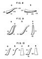
- Fig. 9 shows gutter body 8 as the liquid transporting means.
- FIG. 9 are an oblique view, a side view and a front view of the gutter body 8.
- the gutter body 8 shown in Fig. 9 is in the form of a long and nearly half hollow truncated cone with no bottom.
- the shape of the upper opening 81 and that of the lower opening 82 are both semicircular. Planar shape is long trapezoid and the lower portion is slightly curved. The curving direction is such that the lower opening 82 comes close to the rotating axis when fitted to the mounting frame.
- area of the lower opening is larger than that of the upper opening.
- the area of opening of these liquid transporting means is a length of the arc of the semicircle of the upper and lower end openings.
- Fig. 10 shows a plate body 9 as the liquid transporting means.
- FIG. 10 shows an oblique view, a side view and a front view of the plate body; (d) and (e) show modifications of the plate body shown in (a)-(c) and are an oblique view and a front view, respectively.
- the whole side shape of the plate body 9 shown in (a)-(c) of Fig. 10 is a long S and the whole planar shape is a long trapezoid.
- area of the lower opening is larger than that of the upper opening.
- the area of opening of these liquid transporting means is a length of the straight line of the upper end opening and is defined to be a length of the straight line or the curve of the lower end opening.
- Fig. 11 shows an agitator blade provided with float 10 which also serves as a mounting frame and slidably fitted to an agitator shaft.
- FIG. 11 (a) and (b) are a plan view of the agitator blade and a sectional view of the agitator blade taken along the line A-A.
- the floats 10, 10 are ring-shaped and have a section of nearly square and these are a float of larger diameter and a float of smaller diameter which are concentrically positioned on the same rotating plane.
- a plurality of tube bodies 12, 12, n---, 12 are fixed to the inner circumferential side face of the floats 10, 10 by fixers 101, 101, ---, 101 (in Fig. 11, each two of four tube bodies 12, 12, 12, 12 are fixed to the floats 10, 10 on the same diameter symmetrically with respect to the rotating axis as an axis of symmetry and the agitator blade is omitted).
- the floats 10, 10 are connected by a central ring 102 provided at the center and supporting rods 103, 103.
- a protrusion 104 is provided at the inner peripheral face of the central ring 102.
- a groove 21 is cut on the outer peripheral face of the agitator shaft 2 along its longer axis.
- the agitator blade 1 can be slidably attached to the agitator shaft 2 by inserting the agitator shaft 2 through the central ring 102 and fitting the groove 21 of the agitator shaft with the protrusion 104.
- Fig. 12 shows the agitator blade of the present invention comprising an agitator shaft to which tube bodies are fitted at an angle of 0 to the radial direction of rotating plane by the mounting frame.
- Fig. 12 shows a plan view of the agitator blade and
- b) shows a sectional view of the agitator blade shown in (a) taken along the line B-B.
- the tube body 12 is attached to the top end of the mounting frame 11 at an inclinaton angle of about 45 to the rotating axis 2.
- the tube 12 is provided at substantially 0 ° to the radial direction of its rotating plane, namely, on the radius of the rotating plane.
- the four mounting frames 11, 11, 11, 11 provided with the tube bodies 12 are arranged on the outer periphery of the central ring 102 at a center angle of 90 ° .
- the tube body 12 is an almost straight cylinder.
- the upper end is nearly horizontally bent and the top end is flattened in horizontal direction.
- the shape of the lower opening is circle.
- the agitator shaft 2 is inserted through the central ring 102.
- the upper opening 124 and the lower opening 125 of the tube body 12 are respectively a dicharge opening and and intake opening irrespective of the direction of rotating direction of the agitator blade.
- Figs. 13 and 14 show the agitator blades of the present invention where the liquid transporting means are hollow truncated cone bodies. (a) in Fig. 13 shows a plan view of the agitator blade and (b) shows a sectional view of the agitator blade taken along C-C.
- Fig. 14 shows a plan view of the agitator blade and (b) shows a sectional view of the agitator blade taken along D-D.
- the hollow truncated cone body 201 is the liquid transporting means which is attached to the agitator shaft 2 with the longer axis thereof being allowed to nearly coincide with the longer axis of the agitator shaft 2.
- Four baffles 203, 203, 203, 203 are provided at equal intervals on the inner peripheral face of this hollow truncated cone body along the inclination of the inner peripheral face.
- This hollow truncated cone body 201 is in the form of a reverse truncated cone with the larger opening being an upper opening and arranged on the central ring 102 through mounting frame 11. Through this central ring 102 is inserted the agitator shaft 2.
- the lower opening 204 of smaller diameter and the upper opening 205 of larger diameter are respectively an intake opening and a discharge opening irrespective of its rotating direction.
- the liquid in the agitation tank is scooped up from the lower opening 204 as an intake opening and is allowed to rise along the inner peripheral face of this hollow truncated cone body 201 and discharged from the lower opening 205 as a discharge opening by rotating the agitator blade.
- the agitator blade shown in Fig. 14 is substantially not different from the agitator blade shown in Fig. 13 except that a hollow truncated cone body 202 having a smaller diameter than that of the hollow truncated cone body 201 and equal in gradient of peripheral wall to the hollow truncated cone body 201 is concentrically provided in the hollow truncated cone body 201, no baffles are provided on the inner peripheral faces of the hollow truncated cone bodies 201 and 202, and the liquid in the agitation tank is allowed to rise through the space 206 between the hollow truncated cone bodies 201 and 202 and along the inner peripheral face of the hollow truncated cone body 202.
- the agitation tank shown in Fig. 3 was used as a fermentation equipment.
- agitator blade of the present invention facilitated thorough defoamation without any defoaming agent. There was no substantial difference in power required over a case where no agitator blade of the present invention was used.
- the agitator blade and the method of agitation using this agitator blade of the present invention makes it possible to completely defoam without any defoaming agent in agitation of foamable liquids. There is no difficulty encountered in fermentation and culturing. No defoaming agents are left unremoved as impurity in the product. High quality of the product is secured. No additional labor is required in order to remove the defoaming agent from the product. A treatment of waste liquid is effected without any difficulty.
- the inner peripheral face of the agitation tank and the surface of heating cooling apparatuses can be cleaned and the heating surface area can be effectively used without stopping the operation in the agitation tank. Efficient mixing of liquids having different specific gravities and differing in solid content is also possible.
Landscapes
- Chemical & Material Sciences (AREA)
- Chemical Kinetics & Catalysis (AREA)
- Mixers Of The Rotary Stirring Type (AREA)
- Apparatus Associated With Microorganisms And Enzymes (AREA)
- Accessories For Mixers (AREA)
- Cleaning By Liquid Or Steam (AREA)
Priority Applications (2)
| Application Number | Priority Date | Filing Date | Title |
|---|---|---|---|
| EP98107451A EP0861685B1 (de) | 1993-03-31 | 1994-03-23 | Rührertank |
| DK98107451T DK0861685T3 (da) | 1993-03-31 | 1994-03-23 | Omrøringsbeholder |
Applications Claiming Priority (3)
| Application Number | Priority Date | Filing Date | Title |
|---|---|---|---|
| JP9512893 | 1993-03-31 | ||
| JP95128/93 | 1993-03-31 | ||
| JP9512893 | 1993-03-31 |
Related Child Applications (1)
| Application Number | Title | Priority Date | Filing Date |
|---|---|---|---|
| EP98107451.1 Division-Into | 1998-04-23 |
Publications (2)
| Publication Number | Publication Date |
|---|---|
| EP0619136A1 true EP0619136A1 (de) | 1994-10-12 |
| EP0619136B1 EP0619136B1 (de) | 1999-07-14 |
Family
ID=14129191
Family Applications (2)
| Application Number | Title | Priority Date | Filing Date |
|---|---|---|---|
| EP98107451A Expired - Lifetime EP0861685B1 (de) | 1993-03-31 | 1994-03-23 | Rührertank |
| EP94104601A Expired - Lifetime EP0619136B1 (de) | 1993-03-31 | 1994-03-23 | Verfahren zum Schaumzerstören |
Family Applications Before (1)
| Application Number | Title | Priority Date | Filing Date |
|---|---|---|---|
| EP98107451A Expired - Lifetime EP0861685B1 (de) | 1993-03-31 | 1994-03-23 | Rührertank |
Country Status (4)
| Country | Link |
|---|---|
| EP (2) | EP0861685B1 (de) |
| JP (2) | JP3253212B2 (de) |
| DE (2) | DE69419444T2 (de) |
| DK (2) | DK0619136T3 (de) |
Cited By (10)
| Publication number | Priority date | Publication date | Assignee | Title |
|---|---|---|---|---|
| EP0916390A1 (de) * | 1997-11-14 | 1999-05-19 | Kansai Chemical Engineering Co. Ltd | Vorrichtung und Verfahren zur Flüssigkeitsejektion |
| EP1033164A3 (de) * | 1999-02-22 | 2001-08-29 | Kansai Chemical Engineering Co. Ltd | Vorrichtung und Verfahren zum Ausschleudern einer Flüssigkeit |
| DE102009054202B3 (de) * | 2009-11-21 | 2011-06-30 | Feldhans-Becker, Dominik, 47665 | Vorrichtung zum Einstellen von Mischwendeln |
| CN108786545A (zh) * | 2018-06-21 | 2018-11-13 | 四川汇宇生物技术有限公司 | 一种明胶液搅拌器 |
| CN110652903A (zh) * | 2019-09-24 | 2020-01-07 | 广东东荣金属制品有限公司 | 一种超高速旋转多刀头气液切割混合氧合器 |
| CN114405339A (zh) * | 2022-01-10 | 2022-04-29 | 绍兴市质量技术监督检测院 | 一种染料的混匀制备装置 |
| CN114505286A (zh) * | 2022-02-14 | 2022-05-17 | 广西力合城市矿产再生资源科技有限公司 | 一种不锈钢废渣回收处理设备及工艺 |
| CN117448136A (zh) * | 2023-11-20 | 2024-01-26 | 品源(随州)现代农业发展有限公司 | 一种香菇酱发酵装置及工艺 |
| CN118217872A (zh) * | 2024-05-27 | 2024-06-21 | 中国石油大学(华东) | 一种粘弹性泡沫动态可持续生成和注入装置及其应用 |
| CN118788286A (zh) * | 2024-09-12 | 2024-10-18 | 上海数郜机电有限公司 | 一种气升集液搅拌式反应器 |
Families Citing this family (21)
| Publication number | Priority date | Publication date | Assignee | Title |
|---|---|---|---|---|
| AU754116B2 (en) * | 1999-02-22 | 2002-11-07 | Kansai Chemical Engineering Co., Ltd. | Liquid ejection apparatus and liquid ejection method |
| JP3525126B2 (ja) | 1999-08-25 | 2004-05-10 | 関西化学機械製作株式会社 | 晶析装置および晶析方法 |
| US7011708B2 (en) * | 2000-09-28 | 2006-03-14 | Kansai Chemical Engineering Co. Ltd. | Heat transfer device |
| JP4882156B2 (ja) * | 2001-03-30 | 2012-02-22 | Dic株式会社 | ポリウレタン水分散液の製造法 |
| EP1645612A2 (de) | 2004-09-15 | 2006-04-12 | Konica Minolta Medical & Graphic, Inc. | Radiographische Bilderzeugungsvorrichtung und -methode |
| FR2892642B1 (fr) * | 2005-10-28 | 2007-11-30 | Prosign Sa | Fondoir pour homogeneiser et chauffer un produit, notamment une composition de marquage au sol |
| JP5140566B2 (ja) * | 2008-12-01 | 2013-02-06 | 関西化学機械製作株式会社 | 撹拌装置 |
| JP5288179B2 (ja) * | 2008-12-16 | 2013-09-11 | 大日本印刷株式会社 | 撹拌装置 |
| JP5178629B2 (ja) * | 2009-05-20 | 2013-04-10 | 株式会社仲田コーティング | 攪拌機の洗浄用装置 |
| JP6109006B2 (ja) * | 2013-08-07 | 2017-04-05 | 住友重機械プロセス機器株式会社 | 撹拌装置 |
| JP2015047540A (ja) * | 2013-08-30 | 2015-03-16 | 株式会社石井鐵工所 | 遠心撹拌体 |
| CN104437172A (zh) * | 2014-12-12 | 2015-03-25 | 成都艺辰德迅科技有限公司 | 一种利用物联网自动控制的奶油搅拌机装置 |
| CN109126599A (zh) * | 2018-09-14 | 2019-01-04 | 蒋友明 | 鱼饲料制备装置 |
| CN109224926B (zh) * | 2018-10-24 | 2021-09-14 | 吉安螃蟹王国科技有限公司 | 一种可伸缩防分层的手动油漆调色搅拌设备 |
| JP6958879B2 (ja) * | 2019-04-26 | 2021-11-02 | 泰喜物産株式会社 | 豆腐類の連続製造に使用する攪拌体および該攪拌体を備えた豆腐類の連続製造装置 |
| CN112831407A (zh) * | 2020-12-25 | 2021-05-25 | 江苏大明生物工程装备有限公司 | 一种带有搅拌器的大型好氧发酵罐 |
| JP7121958B1 (ja) * | 2021-03-17 | 2022-08-19 | 関西化学機械製作株式会社 | 反応装置およびそれを用いた反応生成物の製造方法 |
| JP7169602B1 (ja) | 2021-09-29 | 2022-11-11 | 関西化学機械製作株式会社 | 散液デバイスおよびそれを用いた反応装置 |
| JP7252579B1 (ja) * | 2021-12-17 | 2023-04-05 | 関西化学機械製作株式会社 | 処理液の循環方法、ならびにそれに使用する散液デバイスおよび処理液循環装置 |
| JP7126183B1 (ja) | 2022-01-25 | 2022-08-26 | 関西化学機械製作株式会社 | 散液デバイスならびにそれを用いた散液装置 |
| WO2023243335A1 (ja) * | 2022-06-14 | 2023-12-21 | 関西化学機械製作株式会社 | 微生物培養装置およびそれを用いた微生物の培養方法 |
Citations (14)
| Publication number | Priority date | Publication date | Assignee | Title |
|---|---|---|---|---|
| DE185488C (de) * | 1905-11-08 | 1907-05-24 | Vorrichtung zur Mischung von Flüssigkeiten verschiedenen spezifischen Gewichtes oder eines schweren Niederschlages und einer Flüssigkeit | |
| US2143652A (en) * | 1936-09-16 | 1939-01-10 | Gaertner Moritz | Positively controlled vertical agitator and conditioner |
| FR2009464A1 (de) * | 1968-05-28 | 1970-02-06 | Kaelin J R | |
| DE1658067A1 (de) * | 1967-10-13 | 1970-07-02 | Friehe Dipl Ing Bernhard | Belueftungsvorrichtung fuer die biologische Reinigung von Abwasser |
| DE1658115A1 (de) * | 1967-11-15 | 1970-08-20 | Passavant Werke | Vorrichtung zum Einbringen von Gasen,z.B.von Luft,in Abwasser od.dgl.Fluessigkeiten |
| DE1941146A1 (de) * | 1969-08-13 | 1971-02-25 | Zimmer Geb Goldenbaum | Rotorschaufel,insbesondere fuer Abwasserbehandlung |
| DE1963614A1 (de) * | 1969-12-19 | 1971-06-24 | Bamag Verfahrenstechnik Gmbh | Einrichtung zur Begasung von Fluessigkeiten |
| DE1964125A1 (de) * | 1969-12-22 | 1971-06-24 | Babcock & Wilcox Ag | Einrichtung zum Belueften von Fluessigkeiten |
| DE1609032B1 (de) * | 1965-10-24 | 1972-03-23 | Clow Corp | Vorrichtung zum einbringen von gas in eine in einem behaelter befindliche fluessigkeit |
| DE2418679A1 (de) * | 1974-02-28 | 1975-10-30 | Sotralentz Sa | Vorrichtung zum verspruehen von klaerwasser in luft |
| EP0000293A1 (de) * | 1977-07-05 | 1979-01-10 | Biomechanics Limited | Vorrichtung und Verfahren zur anaeroben Zersetzung von biologisch abbaubarem Abfall |
| DE2923375A1 (de) * | 1978-06-12 | 1979-12-13 | Kaelin J R | Oberflaechenbelueftungskreisel |
| DE2844038A1 (de) * | 1978-10-09 | 1980-04-24 | Selwig & Lange Maschf | Einrichtung zur innigen vermischung von zwei stoffkomponenten, von denen zumindest eine fluessig ist |
| SU914077A1 (ru) * | 1980-02-27 | 1982-03-23 | Kishinevskij Polt Inst | Устройство для перемешивания жидкостей 1 |
Family Cites Families (1)
| Publication number | Priority date | Publication date | Assignee | Title |
|---|---|---|---|---|
| US3591149A (en) * | 1969-01-16 | 1971-07-06 | Passavant Werke | Aeration apparatus |
-
1994
- 1994-03-02 JP JP05479994A patent/JP3253212B2/ja not_active Expired - Lifetime
- 1994-03-23 DE DE69419444T patent/DE69419444T2/de not_active Expired - Lifetime
- 1994-03-23 DE DE69432802T patent/DE69432802T2/de not_active Expired - Lifetime
- 1994-03-23 DK DK94104601T patent/DK0619136T3/da active
- 1994-03-23 DK DK98107451T patent/DK0861685T3/da active
- 1994-03-23 EP EP98107451A patent/EP0861685B1/de not_active Expired - Lifetime
- 1994-03-23 EP EP94104601A patent/EP0619136B1/de not_active Expired - Lifetime
-
2001
- 2001-08-30 JP JP2001261082A patent/JP3677227B2/ja not_active Expired - Lifetime
Patent Citations (14)
| Publication number | Priority date | Publication date | Assignee | Title |
|---|---|---|---|---|
| DE185488C (de) * | 1905-11-08 | 1907-05-24 | Vorrichtung zur Mischung von Flüssigkeiten verschiedenen spezifischen Gewichtes oder eines schweren Niederschlages und einer Flüssigkeit | |
| US2143652A (en) * | 1936-09-16 | 1939-01-10 | Gaertner Moritz | Positively controlled vertical agitator and conditioner |
| DE1609032B1 (de) * | 1965-10-24 | 1972-03-23 | Clow Corp | Vorrichtung zum einbringen von gas in eine in einem behaelter befindliche fluessigkeit |
| DE1658067A1 (de) * | 1967-10-13 | 1970-07-02 | Friehe Dipl Ing Bernhard | Belueftungsvorrichtung fuer die biologische Reinigung von Abwasser |
| DE1658115A1 (de) * | 1967-11-15 | 1970-08-20 | Passavant Werke | Vorrichtung zum Einbringen von Gasen,z.B.von Luft,in Abwasser od.dgl.Fluessigkeiten |
| FR2009464A1 (de) * | 1968-05-28 | 1970-02-06 | Kaelin J R | |
| DE1941146A1 (de) * | 1969-08-13 | 1971-02-25 | Zimmer Geb Goldenbaum | Rotorschaufel,insbesondere fuer Abwasserbehandlung |
| DE1963614A1 (de) * | 1969-12-19 | 1971-06-24 | Bamag Verfahrenstechnik Gmbh | Einrichtung zur Begasung von Fluessigkeiten |
| DE1964125A1 (de) * | 1969-12-22 | 1971-06-24 | Babcock & Wilcox Ag | Einrichtung zum Belueften von Fluessigkeiten |
| DE2418679A1 (de) * | 1974-02-28 | 1975-10-30 | Sotralentz Sa | Vorrichtung zum verspruehen von klaerwasser in luft |
| EP0000293A1 (de) * | 1977-07-05 | 1979-01-10 | Biomechanics Limited | Vorrichtung und Verfahren zur anaeroben Zersetzung von biologisch abbaubarem Abfall |
| DE2923375A1 (de) * | 1978-06-12 | 1979-12-13 | Kaelin J R | Oberflaechenbelueftungskreisel |
| DE2844038A1 (de) * | 1978-10-09 | 1980-04-24 | Selwig & Lange Maschf | Einrichtung zur innigen vermischung von zwei stoffkomponenten, von denen zumindest eine fluessig ist |
| SU914077A1 (ru) * | 1980-02-27 | 1982-03-23 | Kishinevskij Polt Inst | Устройство для перемешивания жидкостей 1 |
Non-Patent Citations (1)
| Title |
|---|
| SOVIET INVENTIONS ILLUSTRATED Section Ch Week K041, 9 March 1983 Derwent World Patents Index; Class J02, AN 09180 * |
Cited By (18)
| Publication number | Priority date | Publication date | Assignee | Title |
|---|---|---|---|---|
| EP0916390A1 (de) * | 1997-11-14 | 1999-05-19 | Kansai Chemical Engineering Co. Ltd | Vorrichtung und Verfahren zur Flüssigkeitsejektion |
| US6241381B1 (en) | 1997-11-14 | 2001-06-05 | Kansai Chemical Eng. Col. Ltd. | Liquid ejection apparatus and liquid ejection method |
| US6334704B2 (en) | 1997-11-14 | 2002-01-01 | Kansai Chemical Eng. Col. Ltd. | Liquid ejection apparatus and liquid ejection method |
| CN1090527C (zh) * | 1997-11-14 | 2002-09-11 | 关西化学机械制作株式会社 | 液体喷射装置和液体喷射方法 |
| RU2203128C2 (ru) * | 1997-11-14 | 2003-04-27 | Кансай Кемикал Инджиниринг Ко., Лтд. | Устройство для эжекции жидкости и способ эжекции с использованием этого устройства |
| KR100394432B1 (ko) * | 1997-11-14 | 2003-10-23 | 간사이 가가쿠 기카이 세사쿠 가부시키 가이샤 | 액체분사장치및액체분사방법 |
| EP1033164A3 (de) * | 1999-02-22 | 2001-08-29 | Kansai Chemical Engineering Co. Ltd | Vorrichtung und Verfahren zum Ausschleudern einer Flüssigkeit |
| US6341889B1 (en) | 1999-02-22 | 2002-01-29 | Kansai Chemical Eng. Col. Ltd. | Method for distributing liquid by controlling rotation speed of a shaft as a function of the liquid depth in a tank |
| DE102009054202B3 (de) * | 2009-11-21 | 2011-06-30 | Feldhans-Becker, Dominik, 47665 | Vorrichtung zum Einstellen von Mischwendeln |
| CN108786545A (zh) * | 2018-06-21 | 2018-11-13 | 四川汇宇生物技术有限公司 | 一种明胶液搅拌器 |
| CN110652903A (zh) * | 2019-09-24 | 2020-01-07 | 广东东荣金属制品有限公司 | 一种超高速旋转多刀头气液切割混合氧合器 |
| CN114405339A (zh) * | 2022-01-10 | 2022-04-29 | 绍兴市质量技术监督检测院 | 一种染料的混匀制备装置 |
| CN114505286A (zh) * | 2022-02-14 | 2022-05-17 | 广西力合城市矿产再生资源科技有限公司 | 一种不锈钢废渣回收处理设备及工艺 |
| CN117448136A (zh) * | 2023-11-20 | 2024-01-26 | 品源(随州)现代农业发展有限公司 | 一种香菇酱发酵装置及工艺 |
| CN117448136B (zh) * | 2023-11-20 | 2024-06-07 | 品源(随州)现代农业发展有限公司 | 一种香菇酱发酵装置及工艺 |
| CN118217872A (zh) * | 2024-05-27 | 2024-06-21 | 中国石油大学(华东) | 一种粘弹性泡沫动态可持续生成和注入装置及其应用 |
| CN118788286A (zh) * | 2024-09-12 | 2024-10-18 | 上海数郜机电有限公司 | 一种气升集液搅拌式反应器 |
| CN118788286B (zh) * | 2024-09-12 | 2025-01-24 | 上海数郜机电有限公司 | 一种气升集液搅拌式反应器 |
Also Published As
| Publication number | Publication date |
|---|---|
| EP0861685A2 (de) | 1998-09-02 |
| JP3677227B2 (ja) | 2005-07-27 |
| EP0861685B1 (de) | 2003-06-04 |
| DE69432802D1 (de) | 2003-07-10 |
| DE69419444D1 (de) | 1999-08-19 |
| DK0861685T3 (da) | 2003-06-23 |
| JPH06335627A (ja) | 1994-12-06 |
| EP0619136B1 (de) | 1999-07-14 |
| DK0619136T3 (da) | 1999-11-29 |
| DE69432802T2 (de) | 2004-05-06 |
| JP3253212B2 (ja) | 2002-02-04 |
| DE69419444T2 (de) | 2000-03-30 |
| JP2002119838A (ja) | 2002-04-23 |
| EP0861685A3 (de) | 2000-02-09 |
Similar Documents
| Publication | Publication Date | Title |
|---|---|---|
| EP0619136A1 (de) | Rührerblatt und Rührverfahren | |
| JP3797644B2 (ja) | 液体を噴出せしめる方法 | |
| EP0916390B1 (de) | Vorrichtung und Verfahren zur Flüssigkeitsejektion | |
| US3341450A (en) | Gasification apparatus and method | |
| AU2006200479B2 (en) | Agitation apparatus and method for dry solids addition to fluid | |
| CA2298879C (en) | Liquid ejection apparatus and liquid ejection method | |
| JP2000271404A (ja) | 蒸留塔塔底加熱装置および加熱方法 | |
| AU720728B2 (en) | Mixer sparging apparatus | |
| EP0947240A3 (de) | Rührwerk mit senkrechter Achse | |
| JP3554239B2 (ja) | 液体噴出装置および液体噴出方法 | |
| JP2000271404A5 (de) | ||
| EP0338967B1 (de) | Vorrichtung zur Behandlung einer Aufschlämmung mittels Gas-Flüssigkeits-Kontaktverfahren | |
| KR20010015571A (ko) | 개선된 혼합 및 폭기 장치 | |
| US4272461A (en) | Apparatus for mixing gases with liquids | |
| JP3337357B2 (ja) | 反応槽の回転円盤型消泡装置 | |
| RU2374186C2 (ru) | Устройство для очистки жидкости и пены | |
| US4374030A (en) | Method for separating a dispersed phase from a continuous phase | |
| US4336144A (en) | Method for mixing gases with liquids | |
| US5015322A (en) | Tank arrangement particularly designed for chemical milling operations | |
| AU754116B2 (en) | Liquid ejection apparatus and liquid ejection method | |
| JP3820313B2 (ja) | 竪型撹拌装置の撹拌翼構造 | |
| JPS6021994Y2 (ja) | 醸造用撹拌装置 | |
| SU1212541A1 (ru) | Аппарат дл контакта газа и жидкости | |
| EP0100620A1 (de) | Abtrennung einer leichteren Phase von einer Schwereren |
Legal Events
| Date | Code | Title | Description |
|---|---|---|---|
| PUAI | Public reference made under article 153(3) epc to a published international application that has entered the european phase |
Free format text: ORIGINAL CODE: 0009012 |
|
| AK | Designated contracting states |
Kind code of ref document: A1 Designated state(s): CH DE DK FR GB IT LI SE |
|
| K1C1 | Correction of patent application (title page) published |
Effective date: 19941012 |
|
| 17P | Request for examination filed |
Effective date: 19950320 |
|
| 17Q | First examination report despatched |
Effective date: 19960123 |
|
| GRAG | Despatch of communication of intention to grant |
Free format text: ORIGINAL CODE: EPIDOS AGRA |
|
| GRAG | Despatch of communication of intention to grant |
Free format text: ORIGINAL CODE: EPIDOS AGRA |
|
| GRAG | Despatch of communication of intention to grant |
Free format text: ORIGINAL CODE: EPIDOS AGRA |
|
| GRAH | Despatch of communication of intention to grant a patent |
Free format text: ORIGINAL CODE: EPIDOS IGRA |
|
| GRAH | Despatch of communication of intention to grant a patent |
Free format text: ORIGINAL CODE: EPIDOS IGRA |
|
| GRAA | (expected) grant |
Free format text: ORIGINAL CODE: 0009210 |
|
| AK | Designated contracting states |
Kind code of ref document: B1 Designated state(s): CH DE DK FR GB IT LI SE |
|
| PG25 | Lapsed in a contracting state [announced via postgrant information from national office to epo] |
Ref country code: SE Free format text: THE PATENT HAS BEEN ANNULLED BY A DECISION OF A NATIONAL AUTHORITY Effective date: 19990714 Ref country code: IT Free format text: LAPSE BECAUSE OF FAILURE TO SUBMIT A TRANSLATION OF THE DESCRIPTION OR TO PAY THE FEE WITHIN THE PRESCRIBED TIME-LIMIT;WARNING: LAPSES OF ITALIAN PATENTS WITH EFFECTIVE DATE BEFORE 2007 MAY HAVE OCCURRED AT ANY TIME BEFORE 2007. THE CORRECT EFFECTIVE DATE MAY BE DIFFERENT FROM THE ONE RECORDED. Effective date: 19990714 |
|
| REG | Reference to a national code |
Ref country code: CH Ref legal event code: EP |
|
| REF | Corresponds to: |
Ref document number: 69419444 Country of ref document: DE Date of ref document: 19990819 |
|
| ET | Fr: translation filed | ||
| REG | Reference to a national code |
Ref country code: CH Ref legal event code: NV Representative=s name: BOVARD AG PATENTANWAELTE |
|
| REG | Reference to a national code |
Ref country code: DK Ref legal event code: T3 |
|
| PLBE | No opposition filed within time limit |
Free format text: ORIGINAL CODE: 0009261 |
|
| STAA | Information on the status of an ep patent application or granted ep patent |
Free format text: STATUS: NO OPPOSITION FILED WITHIN TIME LIMIT |
|
| 26N | No opposition filed | ||
| REG | Reference to a national code |
Ref country code: GB Ref legal event code: IF02 |
|
| REG | Reference to a national code |
Ref country code: CH Ref legal event code: PFA Owner name: KANSAI CHEMICAL ENGINEERING CO. LTD Free format text: KANSAI CHEMICAL ENGINEERING CO. LTD#9-7, MINAMINANAMATSU-CHO 2-CHOME#AMAGASAKI-SHI HYOGO 660 (JP) -TRANSFER TO- KANSAI CHEMICAL ENGINEERING CO. LTD#9-7, MINAMINANAMATSU-CHO 2-CHOME#AMAGASAKI-SHI HYOGO 660 (JP) |
|
| PGFP | Annual fee paid to national office [announced via postgrant information from national office to epo] |
Ref country code: GB Payment date: 20130320 Year of fee payment: 20 Ref country code: FR Payment date: 20130325 Year of fee payment: 20 Ref country code: DK Payment date: 20130312 Year of fee payment: 20 Ref country code: CH Payment date: 20130312 Year of fee payment: 20 Ref country code: DE Payment date: 20130320 Year of fee payment: 20 |
|
| REG | Reference to a national code |
Ref country code: DK Ref legal event code: EUP Effective date: 20140323 |
|
| REG | Reference to a national code |
Ref country code: DE Ref legal event code: R071 Ref document number: 69419444 Country of ref document: DE |
|
| REG | Reference to a national code |
Ref country code: CH Ref legal event code: PL |
|
| REG | Reference to a national code |
Ref country code: GB Ref legal event code: PE20 Expiry date: 20140322 |
|
| PG25 | Lapsed in a contracting state [announced via postgrant information from national office to epo] |
Ref country code: GB Free format text: LAPSE BECAUSE OF EXPIRATION OF PROTECTION Effective date: 20140322 Ref country code: DE Free format text: LAPSE BECAUSE OF EXPIRATION OF PROTECTION Effective date: 20140325 |