EP0619138A1 - Procédé de chargement et déchargement de catalyseur pulvérulent - Google Patents
Procédé de chargement et déchargement de catalyseur pulvérulent Download PDFInfo
- Publication number
- EP0619138A1 EP0619138A1 EP94400775A EP94400775A EP0619138A1 EP 0619138 A1 EP0619138 A1 EP 0619138A1 EP 94400775 A EP94400775 A EP 94400775A EP 94400775 A EP94400775 A EP 94400775A EP 0619138 A1 EP0619138 A1 EP 0619138A1
- Authority
- EP
- European Patent Office
- Prior art keywords
- enclosure
- unloading
- loading
- container
- catalyst
- Prior art date
- Legal status (The legal status is an assumption and is not a legal conclusion. Google has not performed a legal analysis and makes no representation as to the accuracy of the status listed.)
- Granted
Links
Images
Classifications
-
- B—PERFORMING OPERATIONS; TRANSPORTING
- B65—CONVEYING; PACKING; STORING; HANDLING THIN OR FILAMENTARY MATERIAL
- B65D—CONTAINERS FOR STORAGE OR TRANSPORT OF ARTICLES OR MATERIALS, e.g. BAGS, BARRELS, BOTTLES, BOXES, CANS, CARTONS, CRATES, DRUMS, JARS, TANKS, HOPPERS, FORWARDING CONTAINERS; ACCESSORIES, CLOSURES, OR FITTINGS THEREFOR; PACKAGING ELEMENTS; PACKAGES
- B65D88/00—Large containers
- B65D88/54—Large containers characterised by means facilitating filling or emptying
- B65D88/56—Large containers characterised by means facilitating filling or emptying by tilting
-
- B—PERFORMING OPERATIONS; TRANSPORTING
- B01—PHYSICAL OR CHEMICAL PROCESSES OR APPARATUS IN GENERAL
- B01J—CHEMICAL OR PHYSICAL PROCESSES, e.g. CATALYSIS OR COLLOID CHEMISTRY; THEIR RELEVANT APPARATUS
- B01J8/00—Chemical or physical processes in general, conducted in the presence of fluids and solid particles; Apparatus for such processes
- B01J8/0015—Feeding of the particles in the reactor; Evacuation of the particles out of the reactor
-
- B—PERFORMING OPERATIONS; TRANSPORTING
- B01—PHYSICAL OR CHEMICAL PROCESSES OR APPARATUS IN GENERAL
- B01J—CHEMICAL OR PHYSICAL PROCESSES, e.g. CATALYSIS OR COLLOID CHEMISTRY; THEIR RELEVANT APPARATUS
- B01J2208/00—Processes carried out in the presence of solid particles; Reactors therefor
- B01J2208/00743—Feeding or discharging of solids
- B01J2208/00761—Discharging
Definitions
- the present invention relates to the use of special containers (or containers) for handling pulverulent products which have, for their handling, the following characteristics: pyrophoric, self-oxidizing or self-heating products.
- the pulverulent products are in particular catalysts (in beads, extrusions or pellets or in any other equivalent form) for the conversion or hydroconversion of hydrocarbons, that is to say catalysts for refining, petrochemistry or chemistry. These products can also be adsorbents.
- the containers described in the present invention allow easy and safe handling for the operators and technicians responsible for handling the catalysts. These containers (or containers) are thus suitable for both loading and / or unloading of catalysts as well as storage of these catalysts and their transport under perfect safety conditions, in particular in accordance with "class 4-2 UN" standards.
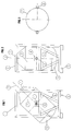
- FIGS 1 to 3 illustrate the device and the container or "container it contains and explain the characteristics of this device.
- the device used in the present invention ( Figure 1) comprises a stable frame resting, for example, on the feet (5) or equivalent devices such as rails or gutters and provided with gripping devices at its upper part.
- This chassis is possibly reinforced by suitable legs such as (6). It can therefore be easily handled using forklifts or cranes and be loaded and moved in trucks, boats or planes.
- the container (2) itself is embedded in the chassis (1) (or metal frame).
- This container is of any traditional form known to those skilled in the art: cylindrical for example, or spherical, or parallelepiped.
- the container is provided with a single orifice (7) at its top and with a solid bottom (9); filling and emptying therefore take place through this same orifice.
- This orifice (7) is fitted with a perfectly sealed valve, preferably a ball valve type valve.
- the container used in the present invention has the advantage of considerably improving the handling because it pivots on itself for emptying, thanks to its installation on its metal frame. This pivoting takes place around a horizontal axis (8) passing through the center of the container and perpendicular to the main axis (3).
- This original device (4) is a non-return pawl which prevents the container from moving in an uncontrolled manner, passing to a lower position during unloading or to a higher position when the container returns to its high position. .
- the container can therefore only pivot at the progressive speed desired by the operator responsible for handling the container.
- the device (8) is similar or equivalent to the escapement wheels of clockwork mechanisms (watches, pendulums, clocks, etc.) cited here by way of reference.
- the container can be equipped with a pressure indicator manometer, a safety valve calibrated to a desired pressure, and / or a device for injecting nitrogen or other gas and purging, equipped with a valve. . It is equipped with a suitable valve system which makes it possible to purge the container when it is empty (with nitrogen for example).
- the container is normally made of steel, stainless steel or not.
- the design of the container and the quality of the ball valve allow this container to withstand a pressure of a few bars, for example 3 bars.
- This container makes it possible to package, store, transport and handle catalysts or adsorbents without a specific atmosphere: nitrogen, argon, water vapor, hydrogen, gaseous hydrocarbons such as methane, chlorine, hydrochloric acid, or mixtures of these. gas. It can contain catalysts or adsorbents of various types, for example used hydrotreatment catalysts containing carbon and sulfur from the hydrotreatment units of petroleum fractions in refineries. These spent catalysts are classified in the category of self-heating products of class 4.2 according to the UN nomenclature. They can be partially passivated using existing technologies such as those using passivating products of the NK103 or CATNAP type.
- Figure 2 shows the device with a container in the high or rest position (full, empty and / or during transport).
- Figure 3 shows the container (2) in aerial view, which can pivot about its horizontal axis (8) around nuts (or similar device).
- the container can have a useful volume of 0.1 to 12 m3, preferably 0.5 to 5 m3.
- It can be designed so that its dimensions allow it to be loaded in sea containers.
- the invention relates to a method of transporting, or loading and unloading a powdery catalyst, by means of an enclosure (intended to contain said catalyst or powdery adsorbent) embedded in a stable support, said support being provided feet or can be moved along a rail, a gutter or any equivalent means, said enclosure being able to pivot about its horizontal axis for the operations of loading and unloading of the catalyst, the process being characterized in that said enclosure (or container ”) pivots by controlled and progressive tilting by means of a non-return pawl akin to an escape wheel.
- the enclosure is of" container "type, preferably metallic, for example stainless steel.
- the method applies to the transport / storage or to the loading and unloading of pyrophoric catalysts or to the transport / storage or to the loading and unloading of self-oxidizing catalysts and / or to the transport / storage or loading and unloading of catalysts with self-heating.
Landscapes
- Chemical & Material Sciences (AREA)
- Engineering & Computer Science (AREA)
- Mechanical Engineering (AREA)
- Organic Chemistry (AREA)
- Chemical Kinetics & Catalysis (AREA)
- Catalysts (AREA)
- Filling Or Discharging Of Gas Storage Vessels (AREA)
- Devices And Processes Conducted In The Presence Of Fluids And Solid Particles (AREA)
- Feeding, Discharge, Calcimining, Fusing, And Gas-Generation Devices (AREA)
- Low-Molecular Organic Synthesis Reactions Using Catalysts (AREA)
Abstract
Description
- La présente invention concerne l'utilisation de conteneurs (ou containers) particuliers pour la manipulation de produits pulvérulents qui présentent, pour leur manipulation, les caractéristiques suivantes : produits pyrophoriques, auto-comburants ou auto-échauffants. Les produits pulvérulents sont notamment des catalyseurs (en billes, extrudés ou pastilles ou sous toute autre forme équivalente) de conversion ou d'hydroconversion d'hydrocarbures c'est-à-dire des catalyseurs de raffinage, pétrochimie ou chimie. Ces produits peuvent également être des adsorbants. Les conteneurs décrits dans la présente invention permettent une manipulation aisée et sans danger pour les opérateurs et techniciens chargés de la manutention des catalyseurs. Ces conteneurs (ou containers) conviennent ainsi aussi bien aux chargements et/ou aux déchargements de catalyseurs qu'au stockage de ces catalyseurs et à leur transport dans des conditions de sécurité parfaite conformes notamment aux normes "classe 4-2 ONU".
- Ces conteneurs sont ainsi avantageusement appelés à remplacer les fûts actuels qui posent des problèmes de recyclage, de manutention et de sécurité.
- Les figures 1 à 3 illustrent l'appareil et le conteneur ou "container qu'il contient et expliquent les caractéristiques de cet appareil.
- L'appareil utilisé dans la présente invention (figure 1) comporte un châssis stable reposant, par exemple, sur les pieds (5) ou dispositifs équivalents tels que rails ou gouttières et muni de dispositifs de préhension à sa partie supérieure. Ce châssis est éventuellement renforcé par des jambages appropriés tels que (6). Il peut donc être manutentionné aisément à l'aide de chariots élévateurs ou de grues et être chargé et déplacé dans des camions, des bateaux ou des avions.
- Le conteneur (2) proprement dit est enchâssé dans le châssis (1) (ou cadre métallique). Ce conteneur est de toute forme traditionnelle connue de l'homme du métier: cylindrique par exemple, ou sphérique, ou parallélipipédique. Le conteneur est muni d'un seul orifice (7) à sa partie haute et d'un fond plein (9); le remplissage et la vidange se font donc par ce même orifice. Cet orifice (7) est équipé d'une vanne parfaitement étanche, de préférence une vanne de type vanne à boule.
- Le conteneur utilisé dans la présente invention a l'avantage d'améliorer considérablement la manipulation parce qu'il pivote sur lui-même pour sa vidange, grâce à son installation sur son cadre métallique. Ce pivotement se fait autour d'un axe horizontal (8) passant par le centre du conteneur et perpendiculairement à l'axe principal (3).
- Grâce à un dispositif original, un basculement intempestif ou inopportun du conteneur pendant sa manipulation, sa vidange, son remplissage ou son stockage ne peut se produire.
- Ce dispositif original (4) est un cliquet antiretour qui empêche le conteneur de se mouvoir de manière incontrôlée, en passant à une position plus basse lors d'un déchargement ou à une position plus haute lors d'un retour du conteneur à sa position haute.
- Le conteneur ne peut donc pivoter qu'à la vitesse progressive souhaitée par l'opérateur responsable de la manutention du conteneur. Le dispositif (8) est semblable ou équivalent aux roues d'échappement des mécanismes d'horlogerie (montres, pendules, horloges, etc...) citées ici par voie de référence.
- Le conteneur peut être équipé d'un manomètre indicateur de pression, d'un clapet de sécurité taré à une pression désirée, et/ou d'un dispositif d'injection d'azote ou autre gaz et de purge, équipé d'une vanne. Il est équipé d'un système de vanne adéquat qui permet de purger le conteneur lorsqu'il est vide (à l'azote par exemple).
- Le conteneur est normalement réalisé en acier, inox ou non.
- La conception du conteneur et la qualité de la vanne à boule permettent à ce conteneur de résister à une pression de quelques bars, par exemple 3 bars.
- Ce conteneur permet de conditionner, de stocker, de transporter et de manipuler des catalyseurs ou des adsorbants sans atmosphère spécifique : azote, argon, vapeur d'eau, hydrogène, hydrocarbures gazeux comme le méthane, chlore, acide chlorhydrique, ou des mélanges de ces gaz. Il peut contenir des catalyseurs ou des adsorbants de divers types, par exemple des catalyseurs d'hydrotraitement usagés contenant du carbone et du soufre provenant des unités d'hydrotraitement de coupes pétrolières en raffinerie. Ces catalyseurs usés sont classés dans la catégorie des produits auto-échauffants de classe 4.2 selon la nomenclature ONU. Ils peuvent être partiellement passivés selon des technologies existantes comme celles utilisant des produits passivants de type NK103 ou CATNAP.
- La figure 2 représente l'appareil avec un conteneur en position haute ou de repos (plein, vide et/ou en cours de transport).
- La figure 3 représente le conteneur (2) en vue aérienne, pouvant pivoter autour de son axe horizontal (8) autour d'écrous (ou dispositif similaire).
- Le conteneur peut avoir un volume utile de 0,1 à 12 m³, de préférence de 0,5 à 5 m³.
- Il peut être conçu pour que ses dimensions permettent de le charger en conteneurs maritimes.
- En résumé, l'invention concerne un procédé de transport, ou de chargement et de déchargement d'un catalyseur pulvérulent, au moyen d'une enceinte (destinée à contenir ledit catalyseur ou adsorbant pulvérulent) enchâssée dans un support stable, ledit support étant muni de pieds ou pouvant être déplacé le long d'un rail, d'une gouttière ou de tout moyen équivalent, ladite enceinte pouvant pivoter autour de son axe horizontal pour les opérations de chargement et de déchargement du catalyseur, le procédé étant caractérisé en ce que ladite enceinte (ou conteneur") pivote par basculement contrôlé et progressif au moyen d'un cliquet antiretour apparenté à une roue d'échappement. L'enceinte est de type "container" de préférence métallique, par exemple en inox.
- Le procédé s'applique au transport/stockage ou au chargement et déchargement de catalyseurs pyrophoriques ou au transport/stockage ou au chargement et déchargement de catalyseurs à caractère auto-comburant et/ou au transport/stockage ou au chargement et déchargement de catalyseurs à caractère auto-échauffant.
Claims (6)
Applications Claiming Priority (2)
| Application Number | Priority Date | Filing Date | Title |
|---|---|---|---|
| FR9304358 | 1993-04-09 | ||
| FR9304358A FR2703666B1 (fr) | 1993-04-09 | 1993-04-09 | Procédé de chargement et déchargement de catalyseur pulvérulent. |
Publications (2)
| Publication Number | Publication Date |
|---|---|
| EP0619138A1 true EP0619138A1 (fr) | 1994-10-12 |
| EP0619138B1 EP0619138B1 (fr) | 1998-07-15 |
Family
ID=9446034
Family Applications (1)
| Application Number | Title | Priority Date | Filing Date |
|---|---|---|---|
| EP94400775A Expired - Lifetime EP0619138B1 (fr) | 1993-04-09 | 1994-04-11 | Procédé de chargement et déchargement de catalyseur pulvérulent |
Country Status (6)
| Country | Link |
|---|---|
| US (1) | US5499746A (fr) |
| EP (1) | EP0619138B1 (fr) |
| JP (1) | JPH06340335A (fr) |
| AT (1) | ATE168284T1 (fr) |
| DE (1) | DE69411614T2 (fr) |
| FR (1) | FR2703666B1 (fr) |
Cited By (1)
| Publication number | Priority date | Publication date | Assignee | Title |
|---|---|---|---|---|
| CN109626007A (zh) * | 2018-12-03 | 2019-04-16 | 佛山市中格威电子有限公司 | 一种适用于胶粘剂出料的翻转式倒料装置 |
Families Citing this family (7)
| Publication number | Priority date | Publication date | Assignee | Title |
|---|---|---|---|---|
| WO2004028769A1 (fr) * | 2002-09-30 | 2004-04-08 | System S.P.A. | Dispositif contenant et fournissant des matieres en vrac |
| RU2279976C2 (ru) * | 2002-09-30 | 2006-07-20 | Систем С.п.А. | Устройство для хранения и подачи сыпучих материалов |
| US10219635B2 (en) * | 2016-04-22 | 2019-03-05 | Salvatore C. Eso, JR. | Nut dispenser device |
| CN106115288A (zh) * | 2016-07-05 | 2016-11-16 | 广西联壮科技股份有限公司 | 基于曲柄连杆机构的粗钡出渣翻转台 |
| CN108163799B (zh) * | 2017-12-26 | 2020-07-10 | 张喜灿 | 一种分酒器及其分酒方法 |
| KR102652577B1 (ko) * | 2021-03-08 | 2024-03-28 | 삼성중공업 주식회사 | 선박에의 촉매 선적 시스템 및 방법 |
| US12522428B2 (en) * | 2023-08-15 | 2026-01-13 | Halliburton Energy Services, Inc. | Rotatable proppant container |
Citations (2)
| Publication number | Priority date | Publication date | Assignee | Title |
|---|---|---|---|---|
| FR1090515A (fr) * | 1953-08-27 | 1955-03-31 | Cie Ind Et Miniere Du Nord Et | Container |
| FR2645567A1 (fr) * | 1989-04-06 | 1990-10-12 | Kehren Roger | Dispositif pour la mise en oeuvre et l'application d'enduits de lissage, colles pour revetements de sols ou analogues |
Family Cites Families (11)
| Publication number | Priority date | Publication date | Assignee | Title |
|---|---|---|---|---|
| US1326077A (en) * | 1919-12-23 | Oil-barbel support | ||
| US1233091A (en) * | 1916-02-12 | 1917-07-10 | Felix Maier | Barrel-stand. |
| US1557273A (en) * | 1924-01-02 | 1925-10-13 | Secrist Joseph | Powder-dispensing device |
| US1779352A (en) * | 1928-12-21 | 1930-10-21 | Allen J Becker | Pouring machine |
| US3874557A (en) * | 1974-02-07 | 1975-04-01 | Harold E Porter | Self-cooling or self-heating beverage container or the like |
| GB1510378A (en) * | 1976-07-16 | 1978-05-10 | Sevalco Ltd | Emptying of containers of powdered or granular products |
| US4278386A (en) * | 1978-04-10 | 1981-07-14 | Eranosian John | Structure for supporting cooking pot for re-fried beans |
| US4662669A (en) * | 1985-09-30 | 1987-05-05 | Amoco Corporation | Spent catalyst container |
| JPH057192Y2 (fr) * | 1985-12-12 | 1993-02-23 | ||
| US4750646A (en) * | 1987-07-16 | 1988-06-14 | Horst Gerich | Feed system |
| FR2626851B1 (fr) * | 1988-02-05 | 1990-07-06 | Step Soc Tech Pulverisation | Dispositif pour faciliter le remplissage des vaporisateurs |
-
1993
- 1993-04-09 FR FR9304358A patent/FR2703666B1/fr not_active Expired - Fee Related
-
1994
- 1994-04-11 DE DE69411614T patent/DE69411614T2/de not_active Expired - Fee Related
- 1994-04-11 EP EP94400775A patent/EP0619138B1/fr not_active Expired - Lifetime
- 1994-04-11 AT AT94400775T patent/ATE168284T1/de active
- 1994-04-11 JP JP6072040A patent/JPH06340335A/ja not_active Withdrawn
- 1994-04-11 US US08/225,725 patent/US5499746A/en not_active Expired - Fee Related
Patent Citations (2)
| Publication number | Priority date | Publication date | Assignee | Title |
|---|---|---|---|---|
| FR1090515A (fr) * | 1953-08-27 | 1955-03-31 | Cie Ind Et Miniere Du Nord Et | Container |
| FR2645567A1 (fr) * | 1989-04-06 | 1990-10-12 | Kehren Roger | Dispositif pour la mise en oeuvre et l'application d'enduits de lissage, colles pour revetements de sols ou analogues |
Cited By (1)
| Publication number | Priority date | Publication date | Assignee | Title |
|---|---|---|---|---|
| CN109626007A (zh) * | 2018-12-03 | 2019-04-16 | 佛山市中格威电子有限公司 | 一种适用于胶粘剂出料的翻转式倒料装置 |
Also Published As
| Publication number | Publication date |
|---|---|
| JPH06340335A (ja) | 1994-12-13 |
| FR2703666B1 (fr) | 1995-06-02 |
| DE69411614D1 (de) | 1998-08-20 |
| US5499746A (en) | 1996-03-19 |
| DE69411614T2 (de) | 1998-11-12 |
| EP0619138B1 (fr) | 1998-07-15 |
| ATE168284T1 (de) | 1998-08-15 |
| FR2703666A1 (fr) | 1994-10-14 |
Similar Documents
| Publication | Publication Date | Title |
|---|---|---|
| EP0619138B1 (fr) | Procédé de chargement et déchargement de catalyseur pulvérulent | |
| US12269672B2 (en) | Transport container for concentrated hydrogen peroxide | |
| EP0280611A1 (fr) | Elément filtrant pour dispositif d'évent et dispositif comportant un tel élément | |
| CA1279282C (fr) | Processus informatise a monorail de manipulation de catalyseur et systeme pour les unites d'hydrotraitement d'hydrocarbures residuaires | |
| WO2019110900A1 (fr) | Container inertable de transport d'une poudre de fabrication additive | |
| EP0999402A1 (fr) | Dispositif de raccordement et de transfert d'un fluide entre un réservoir donneur et un réservoir receveur | |
| US5529097A (en) | Gas tank evacuator | |
| US4890756A (en) | Cylindrical tank with flared upper end | |
| US9387535B2 (en) | Apparatus and method for safely depressurizing milling vials | |
| EP0308544B1 (fr) | Conteneur de liquide inexplosible | |
| JP3065252B2 (ja) | 筒形金属容器の運搬具及びそれを用いた運搬方法 | |
| US20090314135A1 (en) | Cleaning of oil-contaminated solids | |
| CN214296342U (zh) | 液化气体滚卸运输船 | |
| US3760977A (en) | Venting for molten sulphur tankcars | |
| US20070267061A1 (en) | Volume-Displacing Device In Containers, Especially Tanks In Lpg Ships, And A Method Of Using Same | |
| CN204227044U (zh) | 一种气瓶存放车 | |
| US5556012A (en) | Apparatus for handling environmentally sensitive materials | |
| US5273076A (en) | Solvent transport device | |
| CN214863408U (zh) | 密闭装填催化剂的装置 | |
| Berkovitch | Moving dangerous goods in tank containers by road. | |
| EP1188018A1 (fr) | Procede de conditionnement de fluide dans un recipient equipe d'un robinet a pression positive | |
| SU1184712A1 (ru) | Устройство дл погрузки и разгрузки контейнеров,установленное на платформе транспортного средства | |
| FR3056973A1 (fr) | Dispositif de vidange et reconditionnement cuve a cuve pour produits conditionnes en cuves de mille litres a armature metallique ibc et grv | |
| AU3232699A (en) | Jerry can pressure lid | |
| CN2057903U (zh) | 多用运输工具 |
Legal Events
| Date | Code | Title | Description |
|---|---|---|---|
| PUAI | Public reference made under article 153(3) epc to a published international application that has entered the european phase |
Free format text: ORIGINAL CODE: 0009012 |
|
| AK | Designated contracting states |
Kind code of ref document: A1 Designated state(s): AT BE CH DE DK ES GB IT LI LU NL SE |
|
| 17P | Request for examination filed |
Effective date: 19950412 |
|
| GRAG | Despatch of communication of intention to grant |
Free format text: ORIGINAL CODE: EPIDOS AGRA |
|
| 17Q | First examination report despatched |
Effective date: 19970616 |
|
| GRAG | Despatch of communication of intention to grant |
Free format text: ORIGINAL CODE: EPIDOS AGRA |
|
| GRAG | Despatch of communication of intention to grant |
Free format text: ORIGINAL CODE: EPIDOS AGRA |
|
| GRAH | Despatch of communication of intention to grant a patent |
Free format text: ORIGINAL CODE: EPIDOS IGRA |
|
| ITF | It: translation for a ep patent filed | ||
| GRAH | Despatch of communication of intention to grant a patent |
Free format text: ORIGINAL CODE: EPIDOS IGRA |
|
| GRAA | (expected) grant |
Free format text: ORIGINAL CODE: 0009210 |
|
| AK | Designated contracting states |
Kind code of ref document: B1 Designated state(s): AT BE CH DE DK ES GB IT LI LU NL SE |
|
| PG25 | Lapsed in a contracting state [announced via postgrant information from national office to epo] |
Ref country code: ES Free format text: THE PATENT HAS BEEN ANNULLED BY A DECISION OF A NATIONAL AUTHORITY Effective date: 19980715 Ref country code: AT Free format text: LAPSE BECAUSE OF FAILURE TO SUBMIT A TRANSLATION OF THE DESCRIPTION OR TO PAY THE FEE WITHIN THE PRESCRIBED TIME-LIMIT Effective date: 19980715 |
|
| REF | Corresponds to: |
Ref document number: 168284 Country of ref document: AT Date of ref document: 19980815 Kind code of ref document: T |
|
| REG | Reference to a national code |
Ref country code: CH Ref legal event code: EP |
|
| GBT | Gb: translation of ep patent filed (gb section 77(6)(a)/1977) |
Effective date: 19980716 |
|
| REF | Corresponds to: |
Ref document number: 69411614 Country of ref document: DE Date of ref document: 19980820 |
|
| PG25 | Lapsed in a contracting state [announced via postgrant information from national office to epo] |
Ref country code: DK Free format text: LAPSE BECAUSE OF FAILURE TO SUBMIT A TRANSLATION OF THE DESCRIPTION OR TO PAY THE FEE WITHIN THE PRESCRIBED TIME-LIMIT Effective date: 19981015 |
|
| PG25 | Lapsed in a contracting state [announced via postgrant information from national office to epo] |
Ref country code: LI Free format text: LAPSE BECAUSE OF NON-PAYMENT OF DUE FEES Effective date: 19990430 Ref country code: CH Free format text: LAPSE BECAUSE OF NON-PAYMENT OF DUE FEES Effective date: 19990430 |
|
| PLBE | No opposition filed within time limit |
Free format text: ORIGINAL CODE: 0009261 |
|
| STAA | Information on the status of an ep patent application or granted ep patent |
Free format text: STATUS: NO OPPOSITION FILED WITHIN TIME LIMIT |
|
| 26N | No opposition filed | ||
| REG | Reference to a national code |
Ref country code: CH Ref legal event code: PL |
|
| PGFP | Annual fee paid to national office [announced via postgrant information from national office to epo] |
Ref country code: SE Payment date: 20000320 Year of fee payment: 7 |
|
| PGFP | Annual fee paid to national office [announced via postgrant information from national office to epo] |
Ref country code: GB Payment date: 20000323 Year of fee payment: 7 |
|
| PGFP | Annual fee paid to national office [announced via postgrant information from national office to epo] |
Ref country code: BE Payment date: 20000418 Year of fee payment: 7 |
|
| PGFP | Annual fee paid to national office [announced via postgrant information from national office to epo] |
Ref country code: LU Payment date: 20000421 Year of fee payment: 7 |
|
| PGFP | Annual fee paid to national office [announced via postgrant information from national office to epo] |
Ref country code: DE Payment date: 20000427 Year of fee payment: 7 |
|
| PGFP | Annual fee paid to national office [announced via postgrant information from national office to epo] |
Ref country code: NL Payment date: 20000428 Year of fee payment: 7 |
|
| PG25 | Lapsed in a contracting state [announced via postgrant information from national office to epo] |
Ref country code: LU Free format text: LAPSE BECAUSE OF NON-PAYMENT OF DUE FEES Effective date: 20010411 Ref country code: GB Free format text: LAPSE BECAUSE OF NON-PAYMENT OF DUE FEES Effective date: 20010411 |
|
| PG25 | Lapsed in a contracting state [announced via postgrant information from national office to epo] |
Ref country code: SE Free format text: LAPSE BECAUSE OF NON-PAYMENT OF DUE FEES Effective date: 20010412 |
|
| PG25 | Lapsed in a contracting state [announced via postgrant information from national office to epo] |
Ref country code: BE Free format text: LAPSE BECAUSE OF NON-PAYMENT OF DUE FEES Effective date: 20010430 |
|
| BERE | Be: lapsed |
Owner name: EUROPEENNE DE RETRAITEMENT DE CATALYSEURS EURECAT Effective date: 20010430 |
|
| PG25 | Lapsed in a contracting state [announced via postgrant information from national office to epo] |
Ref country code: NL Free format text: LAPSE BECAUSE OF NON-PAYMENT OF DUE FEES Effective date: 20011101 |
|
| GBPC | Gb: european patent ceased through non-payment of renewal fee |
Effective date: 20010411 |
|
| EUG | Se: european patent has lapsed |
Ref document number: 94400775.6 |
|
| NLV4 | Nl: lapsed or anulled due to non-payment of the annual fee |
Effective date: 20011101 |
|
| PG25 | Lapsed in a contracting state [announced via postgrant information from national office to epo] |
Ref country code: DE Free format text: LAPSE BECAUSE OF NON-PAYMENT OF DUE FEES Effective date: 20020201 |
|
| PG25 | Lapsed in a contracting state [announced via postgrant information from national office to epo] |
Ref country code: IT Free format text: LAPSE BECAUSE OF NON-PAYMENT OF DUE FEES;WARNING: LAPSES OF ITALIAN PATENTS WITH EFFECTIVE DATE BEFORE 2007 MAY HAVE OCCURRED AT ANY TIME BEFORE 2007. THE CORRECT EFFECTIVE DATE MAY BE DIFFERENT FROM THE ONE RECORDED. Effective date: 20050411 |