EP0619229B1 - Dispositif pour diviser des produits plats sur plusieurs colonnes de sortie - Google Patents
Dispositif pour diviser des produits plats sur plusieurs colonnes de sortie Download PDFInfo
- Publication number
- EP0619229B1 EP0619229B1 EP94810176A EP94810176A EP0619229B1 EP 0619229 B1 EP0619229 B1 EP 0619229B1 EP 94810176 A EP94810176 A EP 94810176A EP 94810176 A EP94810176 A EP 94810176A EP 0619229 B1 EP0619229 B1 EP 0619229B1
- Authority
- EP
- European Patent Office
- Prior art keywords
- deflecting
- section
- belt
- motor
- deflecting means
- Prior art date
- Legal status (The legal status is an assumption and is not a legal conclusion. Google has not performed a legal analysis and makes no representation as to the accuracy of the status listed.)
- Expired - Lifetime
Links
- 235000015895 biscuits Nutrition 0.000 claims description 13
- 235000019219 chocolate Nutrition 0.000 claims description 3
- 238000011144 upstream manufacturing Methods 0.000 claims 2
- 239000004952 Polyamide Substances 0.000 claims 1
- 229920002647 polyamide Polymers 0.000 claims 1
- 230000007704 transition Effects 0.000 claims 1
- 230000004888 barrier function Effects 0.000 description 5
- 230000001133 acceleration Effects 0.000 description 1
- 238000005352 clarification Methods 0.000 description 1
- 238000004140 cleaning Methods 0.000 description 1
- 238000001514 detection method Methods 0.000 description 1
- 230000000694 effects Effects 0.000 description 1
- 230000001788 irregular Effects 0.000 description 1
- 230000007257 malfunction Effects 0.000 description 1
- 238000004519 manufacturing process Methods 0.000 description 1
Images

Classifications
-
- B—PERFORMING OPERATIONS; TRANSPORTING
- B65—CONVEYING; PACKING; STORING; HANDLING THIN OR FILAMENTARY MATERIAL
- B65G—TRANSPORT OR STORAGE DEVICES, e.g. CONVEYORS FOR LOADING OR TIPPING, SHOP CONVEYOR SYSTEMS OR PNEUMATIC TUBE CONVEYORS
- B65G47/00—Article or material-handling devices associated with conveyors; Methods employing such devices
- B65G47/74—Feeding, transfer, or discharging devices of particular kinds or types
- B65G47/76—Fixed or adjustable ploughs or transverse scrapers
- B65G47/766—Adjustable ploughs or transverse scrapers
-
- B—PERFORMING OPERATIONS; TRANSPORTING
- B65—CONVEYING; PACKING; STORING; HANDLING THIN OR FILAMENTARY MATERIAL
- B65B—MACHINES, APPARATUS OR DEVICES FOR, OR METHODS OF, PACKAGING ARTICLES OR MATERIALS; UNPACKING
- B65B23/00—Packaging fragile or shock-sensitive articles other than bottles; Unpacking eggs
- B65B23/10—Packaging biscuits
- B65B23/12—Arranging, feeding or orientating the biscuits to be packaged
-
- B—PERFORMING OPERATIONS; TRANSPORTING
- B65—CONVEYING; PACKING; STORING; HANDLING THIN OR FILAMENTARY MATERIAL
- B65G—TRANSPORT OR STORAGE DEVICES, e.g. CONVEYORS FOR LOADING OR TIPPING, SHOP CONVEYOR SYSTEMS OR PNEUMATIC TUBE CONVEYORS
- B65G15/00—Conveyors having endless load-conveying surfaces, i.e. belts and like continuous members, to which tractive effort is transmitted by means other than endless driving elements of similar configuration
- B65G15/30—Belts or like endless load-carriers
- B65G15/32—Belts or like endless load-carriers made of rubber or plastics
- B65G15/46—Belts or like endless load-carriers made of rubber or plastics formed with guides
-
- B—PERFORMING OPERATIONS; TRANSPORTING
- B65—CONVEYING; PACKING; STORING; HANDLING THIN OR FILAMENTARY MATERIAL
- B65G—TRANSPORT OR STORAGE DEVICES, e.g. CONVEYORS FOR LOADING OR TIPPING, SHOP CONVEYOR SYSTEMS OR PNEUMATIC TUBE CONVEYORS
- B65G47/00—Article or material-handling devices associated with conveyors; Methods employing such devices
- B65G47/52—Devices for transferring articles or materials between conveyors i.e. discharging or feeding devices
- B65G47/68—Devices for transferring articles or materials between conveyors i.e. discharging or feeding devices adapted to receive articles arriving in one layer from one conveyor lane and to transfer them in individual layers to more than one conveyor lane or to one broader conveyor lane, or vice versa, e.g. combining the flows of articles conveyed by more than one conveyor
- B65G47/71—Devices for transferring articles or materials between conveyors i.e. discharging or feeding devices adapted to receive articles arriving in one layer from one conveyor lane and to transfer them in individual layers to more than one conveyor lane or to one broader conveyor lane, or vice versa, e.g. combining the flows of articles conveyed by more than one conveyor the articles being discharged or distributed to several distinct separate conveyors or to a broader conveyor lane
Definitions
- US-A-5 042 636 describes an apparatus for dividing products from a continuously supplied input column to a plurality of output columns.
- a continuously rotating, endless chain is arranged inclined to the conveying direction of the belt.
- a large number of regularly spaced flags are fastened to the chain, which flags can be pivoted from a raised to a lowered position either outside of one edge of the band by means of a control direction.
- all lowered flags are swung back into the raised position. The lowered flags move the conveyed products laterally into another lane.
- This device has a complicated structure and is therefore complex to manufacture and maintain.
- a column of vessels delivered on a conveyor belt can be divided into a plurality of exit columns.
- a group of vessels is optionally shifted into another lane by means of a pusher transversely to the direction of transport. From this track, the vessels can optionally be deflected into one of several exit tracks by means of a guide element.
- the guide element can be pivoted about a vertical axis.
- the plunger can only be withdrawn from the disengaged position when there are no vessels in its detection area. If this condition does not apply, the vessels in question are pushed over the edge of the conveyor belt, which leads to operational problems.
- a vessel can just leave its downstream end. This vessel then does not get into the intended exit column, which also leads to malfunctions.
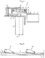
- the device shown comprises a conveyor belt 2 with a horizontal, upper run, on the upper side 4 of which an aligned entry column 6 of biscuits 8 is irregular Distances in the direction of conveyance A is delivered.
- a deflection device 10 distributes this input column 6 to two output columns 12, 14.
- the device 10 comprises a drive wheel 16 arranged on the side of the belt, which is connected to the output shaft 18 of a servo motor 20.
- the axis 22 of the shaft 18 is vertical.
- the axis 26 of a deflection wheel 28, which is parallel to the axis 22, is fastened on an arm 24 which can be pivoted about the axis 22.
- the wheel 28 is in plan view (FIGS. 1 and 2) partially above the conveyor belt 2.
- the arm 24 can be locked by means of a screw 30 in order to be able to adjust the device 10 to different formats or diameters of the biscuits 8.
- a toothed belt 32 is guided around the wheels 16, 28.
- the toothed belt 32 has on one side inside studs 34 which engage in grooves 36 of the wheels 16, 28 for lateral guidance of the belt 32. Teeth 38, which mesh with teeth 40 of the drive wheel 16, extend on both sides of the studs 34.
- the belt 32 has a deflection section 42 and a passage section 44. In the deflection section 42, the lower edge 46 of the belt 32 extends to just above the plane of the surface 4 of the conveyor belt 2.
- the teeth 38 can be used to stiffen the deflection section 42 up to this lower edge 46 can be extended, which is indicated by dashed lines in Figure 3.
- the lower edge 48 is slightly more than the maximum thickness of the biscuits 8 above the surface 4.
- the two sections 42, 44 are approximately the same length, that is to say they each extend over approximately half the circumference of the belt 32.
- a control device 50 is used to control the motor 20. It receives signals from two reflective light barriers 52, 54.
- the light barrier 52 senses the spaces between adjacent biscuits 8 adjacent to the drive wheel 16 in order to start the motor 20 in such a way that the front edge 56 or the trailing edge 58 of the deflection section 42 runs in synchronism with such a space in order to rotate the band 32 either in the deflection position shown in FIG. 1 or in the passage position shown in FIG. 2.
- the tab 60 of the deflecting section 42 protruding beyond the lower edge 48 of the passage section 44 is shown somewhat above for clarification.
- the light barrier 54 senses the front and rear edges 56, 58 of the deflection section 42 in order to stop the motor 20 in such a way that either the rear edge 58 (FIG. 1) or the front edge 56 (FIG. 2) stops adjacent to the drive wheel 16 directly at the edge of the belt 2 .
- a support body 62 can also be attached to the arm 24.
- the support body 62 can have an additional groove for guiding the studs 34. If the output column 12 is to be supplied, the motor 20 is switched on when passing through a space between the biscuits 8 on the rear edge 58, so that the belt 32 runs synchronously with the belt 2 until it has completed half a handling and now the front edge 56 on the Place where the trailing edge 58 was previously (figure 2). Now all the biscuits 8 pass under the belt 32 and the deflecting wheel 28 into the exit column 12.
- the controller 50 can contain a counter which effects the switchover after a selectable first and second number of the gaps detected by the light barrier 52.
- the biscuits 8 can be selected in a selectable ratio of e.g. 1: 1 or 2: 1 can be divided between the two columns 12, 14.
- the motor 20 can also run constantly in order to distribute them evenly between the two output columns 12, 14, and only when the leading or trailing edges 56, 58 pass through the position shown in FIGS. 1 and 2 is briefly braked or accelerated for synchronization with the gaps.
- a plurality of deflection devices 10 can also be arranged in series, which is shown in FIG. 5.
- a very high distribution capacity of, for example, 300 to 2,000 pieces per minute, a high switching capacity with gentle product handling and clear allocation of each product into the two columns 12, 14 are achieved.
- the structure is simple, easily accessible and can be monitored and controlled.
- a scraper 64 indicated in FIG. 2 can also be attached, which scrapes off any biscuit residues from the outside of the flap 60. This makes the device self-cleaning.
- the device can be easily adjusted to different product sizes and formats.
- the light barrier 52 can be attached to the side in an adjustable manner or its signal can be passed on with an adjustable delay.
Landscapes
- Engineering & Computer Science (AREA)
- Mechanical Engineering (AREA)
- Attitude Control For Articles On Conveyors (AREA)
- Discharge Of Articles From Conveyors (AREA)
- Branching, Merging, And Special Transfer Between Conveyors (AREA)
- Structure Of Belt Conveyors (AREA)
Claims (11)
- Dispositif pour diviser des produits plats, posés à plat, en particulier des biscuits ou des morceaux de chocolat, depuis une colonne d'entrée (6) approvisionnée en continu sur plusieurs colonnes de sortie (12, 14), comprenant:- un moyen de transport (2) pour le transport des produits (8);- un moyen de déviation sans fin (32), mené autour d'organes de déviation (16, 28) au-dessus du moyen de transport (2), qui s'étend sur un tronçon de déviation (42) jusqu'immédiatement au-dessus de la face supérieure (4) du moyen de transport (2) et présente sur un tronçon de passage (44) une distance par rapport à cette face supérieure (4), qui est supérieure à l'épaisseur des produits (8), dans lequel une zone de déviation du moyen de déviation (32) est inclinée par rapport à la direction de transport (A) du moyen de transport (2), dans lequel le tronçon de déviation (42) présente une saillie (60) fermement assemblée au moyen de déviation (32), qui dépasse l'arête inférieure (48) du tronçon de passage (44);- un moteur (20) pour l'entraînement du moyen de déviation (32); et- un dispositif de commande (50) pour la commande du moteur (20).
- Dispositif suivant la revendication 1, dans lequel le moyen de déviation (32) ne présente qu'un seul tronçon de déviation (42) et un seul tronçon de passage (44) et la longueur du tronçon de déviation est de préférence approximativement égale à la longueur du tronçon de passage.
- Dispositif suivant la revendication 1 ou 2, dans lequel les organes de déviation sont formés par une roue de commande (16) reliée au moteur (20) et une roue de déviation (28).
- Dispositif suivant l'une quelconque des revendications 1-3, dans lequel la zone de déviation du moyen de déviation (32) est inclinée de 7° à 20° par rapport à la direction de transport (A) du moyen de transport (2), et dans lequel cet angle est réglable de préférence par branchement autour d'un axe (22) de l'organe de déviation amont (16).
- Dispositif suivant l'une quelconque des revendications 1-4, dans lequel le moyen de déviation est une bande (32) et se compose de préférence de polyamide.
- Dispositif suivant la revendication 5, dans lequel la bande (32) présente des moyens de guidage latéral (34) à distance de son bord inférieur (46, 48).
- Dispositif suivant la revendication 5 ou 6, dans lequel la bande (32) est constituée par une courroie dentée, et dans lequel les dents (38) de la courroie dentée ont de préférence un rôle de raidisseurs dans la zone du tronçon de déviation (42).
- Dispositif suivant l'une quelconque des revendications 1-7, dans lequel un premier palpeur (52) est disposé au voisinage de l'organe de déviation amont (16), pour détecter les espaces intermédiaires entre les produits (8), et est relié au dispositif de commande (50), pour commander le moteur (20).
- Dispositif suivant l'une quelconque des revendications 1-8, dans lequel un second palpeur (54) est disposé le long du périmètre du moyen de déviation (32), qui détecte la transition entre le tronçon de déviation (42) et le tronçon de passage (44), pour arrêter le moteur (20), par l'intermédiaire du dispositif de commande (50), dans une position prédéterminée du moyen de déviation (32).
- Dispositif suivant l'une quelconque des revendications 1-9, dans lequel il existe, dans la zone de déviation, un organe d'appui (62) pour soutenir le moyen de déviation (32) en direction verticale et horizontale.
- Dispositif suivant l'une quelconque des revendications 1-10, dans lequel plusieurs moyens de déviation (32) sont montés l'un derrière l'autre.
Applications Claiming Priority (2)
| Application Number | Priority Date | Filing Date | Title |
|---|---|---|---|
| CH1035/93 | 1993-04-05 | ||
| CH103593 | 1993-04-05 |
Publications (2)
| Publication Number | Publication Date |
|---|---|
| EP0619229A1 EP0619229A1 (fr) | 1994-10-12 |
| EP0619229B1 true EP0619229B1 (fr) | 1997-10-15 |
Family
ID=4200932
Family Applications (1)
| Application Number | Title | Priority Date | Filing Date |
|---|---|---|---|
| EP94810176A Expired - Lifetime EP0619229B1 (fr) | 1993-04-05 | 1994-03-23 | Dispositif pour diviser des produits plats sur plusieurs colonnes de sortie |
Country Status (4)
| Country | Link |
|---|---|
| US (1) | US5423409A (fr) |
| EP (1) | EP0619229B1 (fr) |
| JP (1) | JPH06321344A (fr) |
| DE (1) | DE59404297D1 (fr) |
Families Citing this family (15)
| Publication number | Priority date | Publication date | Assignee | Title |
|---|---|---|---|---|
| GB9512903D0 (en) * | 1995-06-24 | 1995-08-30 | Defabs Eng Systems Ltd | Improvements in or relating to article distribution apparatus |
| FR2738231B1 (fr) * | 1995-09-05 | 1997-11-21 | Fege Francois Loic | Dispositif pour repartir des produits d'un convoyeur sur plusieurs voies de sortie |
| US5761883A (en) * | 1995-11-28 | 1998-06-09 | Food Machinery Sales, Inc. | Cookie tray loading machine |
| US5655643A (en) * | 1996-05-08 | 1997-08-12 | United Parcel Service Of America, Inc. | High speed, compound, belted diverter and method of operating same |
| US5979635A (en) * | 1997-10-22 | 1999-11-09 | Industrial Dynamics Co., Ltd. | Container diverter apparatus and method |
| NL1017586C2 (nl) * | 2001-03-13 | 2002-09-20 | Blueprint Holding Bv | Werkwijze en inrichting voor het verpakken van voorwerpen. |
| JP2006504602A (ja) * | 2002-11-02 | 2006-02-09 | アムベック・インコーポレイテッド | 単一のレーンにある連続する物品を複数のレーンに分流するための装置 |
| US7637366B2 (en) * | 2004-06-04 | 2009-12-29 | Shuttleworth, Inc. | High speed diverter |
| CN100448749C (zh) * | 2006-01-04 | 2009-01-07 | 青岛青食有限公司 | 一种饼干自动给料计量包装生产工艺 |
| WO2007147005A2 (fr) * | 2006-06-13 | 2007-12-21 | Arrowhead Conveyor Corporation, Inc. | Appareil de transport |
| US7997405B2 (en) | 2009-07-22 | 2011-08-16 | Arrowhead Systems, Inc. | Sanitary conveyor |
| DE102014203118B4 (de) * | 2014-02-20 | 2019-07-18 | Dürkopp Fördertechnik GmbH | Schaltbare Weiche zum Beeinflussen eines Flusses von Einzelwaren in einem Fördersystem, Fördersystem mit einer derartigen schaltbaren Weiche sowie Verfahren zum Schalten einer derartigen schaltbaren Weiche |
| US9212006B1 (en) * | 2015-01-28 | 2015-12-15 | Laitram, L.L.C. | Conveyor with belt-actuated guide |
| US9988219B2 (en) * | 2016-04-05 | 2018-06-05 | Heraeus Noblelight America Llc | Metal container conveyor systems including diverter mechanisms, and metal container processing systems including the same |
| BE1030670B1 (nl) * | 2022-06-30 | 2024-01-29 | Gb Foods Belgium N V | Inrichting en werkwijze voor het geleiden en ordenen van producten in de voedingsindustrie op een lopende band |
Family Cites Families (5)
| Publication number | Priority date | Publication date | Assignee | Title |
|---|---|---|---|---|
| US3232417A (en) * | 1964-07-27 | 1966-02-01 | C F Butz Engineering | Continuous action deflector for conveyors |
| US3429417A (en) * | 1967-01-20 | 1969-02-25 | Rapistan Inc | Motorized flow diverter |
| JPS60501500A (ja) * | 1983-06-01 | 1985-09-12 | テイマレイラ・ピ−・ティ−・ワイ・リミテッド | ベルトコンベアフレ−ム |
| DE9003468U1 (de) * | 1990-03-24 | 1990-06-21 | Holstein und Kappert AG, 44143 Dortmund | Vorrichtung zum Verbreitern eines einspurig zulaufenden Gefäßstromes |
| US5042636A (en) * | 1990-03-26 | 1991-08-27 | Robert Underwood | Apparatus and method for displacing conveyed articles |
-
1994
- 1994-03-23 DE DE59404297T patent/DE59404297D1/de not_active Expired - Fee Related
- 1994-03-23 EP EP94810176A patent/EP0619229B1/fr not_active Expired - Lifetime
- 1994-03-30 JP JP6060992A patent/JPH06321344A/ja active Pending
- 1994-04-04 US US08/222,032 patent/US5423409A/en not_active Expired - Fee Related
Also Published As
| Publication number | Publication date |
|---|---|
| US5423409A (en) | 1995-06-13 |
| DE59404297D1 (de) | 1997-11-20 |
| JPH06321344A (ja) | 1994-11-22 |
| EP0619229A1 (fr) | 1994-10-12 |
Similar Documents
| Publication | Publication Date | Title |
|---|---|---|
| EP2836447B1 (fr) | Dispositif et procédé de transport de produits en morceaux | |
| DE3915217C2 (de) | Vorrichtung zum Gruppieren von Gegenständen | |
| DE4013687C2 (de) | Förderanlage für Packungen mit integriertem Pufferspeicher | |
| DE2541813C2 (de) | Einrichtung zum Ordnen einer Anzahl ungeordnet herangeführter Behälter zu einer einzigen sich fortbewegenden Reihe | |
| EP2143673B1 (fr) | Dispositif de transport destiné à transporter des articles vers une machine d'emballage | |
| DE3221324C2 (fr) | ||
| EP0619229A1 (fr) | Dispositif pour diviser des produits plats sur plusieurs colonnes de sortie | |
| EP2826735B1 (fr) | Section ajustable de stockage tampon d'un dispositif de convoyage et procédé de stockage intermédiaire d'articles | |
| EP0833791B1 (fr) | Dispositif d'alimentation d'une machine d'emballage | |
| DE1506987B2 (de) | Foerderanlage zum ueberfuehren von gegenstaenden von einer ersten zu einer zweiten foerdereinrichtung | |
| DE102014215106A1 (de) | Verfahren und Vorrichtung zum Fördern von stückigen Produkten | |
| EP0739834A2 (fr) | Dispositif pour tourner des produits pendant le processus de transport | |
| DE1756233A1 (de) | Laengsfoerderer mit einer Vorrichtung zum Drehen von quaderfoermigen Gegenstaenden | |
| EP0868349B1 (fr) | Dispositif pour la formation de groupes de produits en forme de disques empiles | |
| CH635041A5 (de) | Vorrichtung zum aufstellen und stapeln von liegend zugefuehrten gebaeckscheiben und verfahren zum betrieb der vorrichtung. | |
| DE3130308A1 (de) | Vorrichtung zum ausleiten von fehlerhaften produkten aus einem foerderband | |
| DD244112A1 (de) | Vorrichtung zum ueberfuehren von gegenstaenden | |
| DE3644058C1 (de) | Verfahren und Vorrichtung zum Vergroessern der Zahl der Laengsreihen eines Verbandes von Gebaeckstuecken,insbesondere Keksen | |
| DE2733823A1 (de) | Verfahren zur geordneten aufgabe von teilen auf eine ablageflaeche | |
| DE4221464A1 (de) | Aufgabefördereinrichtung zum Aufgeben von Stückgutteilen auf einen Aufnahmeförderer | |
| WO2023118189A1 (fr) | Dispositif et procédé de transport et de répartition | |
| DE68907213T2 (de) | Foerdersystem. | |
| DE102008034266B4 (de) | Vorrichtung zum Drehen einer Teilmenge von Produkten | |
| DE4435199A1 (de) | Verfahren und Vorrichtung zum Erzeugen einer mehrspurigen Reihe von Gegenständen | |
| AT393484B (de) | Vorrichtung zum drehen von packungen |
Legal Events
| Date | Code | Title | Description |
|---|---|---|---|
| PUAI | Public reference made under article 153(3) epc to a published international application that has entered the european phase |
Free format text: ORIGINAL CODE: 0009012 |
|
| AK | Designated contracting states |
Kind code of ref document: A1 Designated state(s): CH DE FR GB IT LI NL |
|
| 17P | Request for examination filed |
Effective date: 19950228 |
|
| 17Q | First examination report despatched |
Effective date: 19960131 |
|
| GRAG | Despatch of communication of intention to grant |
Free format text: ORIGINAL CODE: EPIDOS AGRA |
|
| GRAH | Despatch of communication of intention to grant a patent |
Free format text: ORIGINAL CODE: EPIDOS IGRA |
|
| GRAH | Despatch of communication of intention to grant a patent |
Free format text: ORIGINAL CODE: EPIDOS IGRA |
|
| GRAA | (expected) grant |
Free format text: ORIGINAL CODE: 0009210 |
|
| AK | Designated contracting states |
Kind code of ref document: B1 Designated state(s): CH DE FR GB IT LI NL |
|
| PG25 | Lapsed in a contracting state [announced via postgrant information from national office to epo] |
Ref country code: GB Free format text: LAPSE BECAUSE OF FAILURE TO SUBMIT A TRANSLATION OF THE DESCRIPTION OR TO PAY THE FEE WITHIN THE PRESCRIBED TIME-LIMIT Effective date: 19971015 Ref country code: FR Free format text: LAPSE BECAUSE OF FAILURE TO SUBMIT A TRANSLATION OF THE DESCRIPTION OR TO PAY THE FEE WITHIN THE PRESCRIBED TIME-LIMIT Effective date: 19971015 |
|
| REG | Reference to a national code |
Ref country code: CH Ref legal event code: NV Representative=s name: ISLER & PEDRAZZINI AG Ref country code: CH Ref legal event code: EP |
|
| REF | Corresponds to: |
Ref document number: 59404297 Country of ref document: DE Date of ref document: 19971120 |
|
| ITF | It: translation for a ep patent filed | ||
| PGFP | Annual fee paid to national office [announced via postgrant information from national office to epo] |
Ref country code: DE Payment date: 19980225 Year of fee payment: 5 |
|
| EN | Fr: translation not filed | ||
| PG25 | Lapsed in a contracting state [announced via postgrant information from national office to epo] |
Ref country code: LI Free format text: LAPSE BECAUSE OF NON-PAYMENT OF DUE FEES Effective date: 19980331 Ref country code: CH Free format text: LAPSE BECAUSE OF NON-PAYMENT OF DUE FEES Effective date: 19980331 |
|
| PGFP | Annual fee paid to national office [announced via postgrant information from national office to epo] |
Ref country code: NL Payment date: 19980331 Year of fee payment: 5 |
|
| GBV | Gb: ep patent (uk) treated as always having been void in accordance with gb section 77(7)/1977 [no translation filed] |
Effective date: 19971015 |
|
| PLBE | No opposition filed within time limit |
Free format text: ORIGINAL CODE: 0009261 |
|
| STAA | Information on the status of an ep patent application or granted ep patent |
Free format text: STATUS: NO OPPOSITION FILED WITHIN TIME LIMIT |
|
| 26N | No opposition filed | ||
| REG | Reference to a national code |
Ref country code: CH Ref legal event code: PL |
|
| PG25 | Lapsed in a contracting state [announced via postgrant information from national office to epo] |
Ref country code: NL Free format text: LAPSE BECAUSE OF NON-PAYMENT OF DUE FEES Effective date: 19991001 |
|
| NLV4 | Nl: lapsed or anulled due to non-payment of the annual fee |
Effective date: 19991001 |
|
| PG25 | Lapsed in a contracting state [announced via postgrant information from national office to epo] |
Ref country code: DE Free format text: LAPSE BECAUSE OF NON-PAYMENT OF DUE FEES Effective date: 20000101 |
|
| PG25 | Lapsed in a contracting state [announced via postgrant information from national office to epo] |
Ref country code: IT Free format text: LAPSE BECAUSE OF NON-PAYMENT OF DUE FEES;WARNING: LAPSES OF ITALIAN PATENTS WITH EFFECTIVE DATE BEFORE 2007 MAY HAVE OCCURRED AT ANY TIME BEFORE 2007. THE CORRECT EFFECTIVE DATE MAY BE DIFFERENT FROM THE ONE RECORDED. Effective date: 20050323 |