EP0619237A2 - Caisse de transport - Google Patents
Caisse de transport Download PDFInfo
- Publication number
- EP0619237A2 EP0619237A2 EP94104272A EP94104272A EP0619237A2 EP 0619237 A2 EP0619237 A2 EP 0619237A2 EP 94104272 A EP94104272 A EP 94104272A EP 94104272 A EP94104272 A EP 94104272A EP 0619237 A2 EP0619237 A2 EP 0619237A2
- Authority
- EP
- European Patent Office
- Prior art keywords
- end wall
- frame
- transport box
- box according
- box
- Prior art date
- Legal status (The legal status is an assumption and is not a legal conclusion. Google has not performed a legal analysis and makes no representation as to the accuracy of the status listed.)
- Ceased
Links
- 238000006073 displacement reaction Methods 0.000 claims description 7
- 239000011111 cardboard Substances 0.000 description 6
- 101150006573 PAN1 gene Proteins 0.000 description 2
- 239000000835 fiber Substances 0.000 description 2
- 239000002994 raw material Substances 0.000 description 2
- 238000004519 manufacturing process Methods 0.000 description 1
- 239000002184 metal Substances 0.000 description 1
- 238000000034 method Methods 0.000 description 1
- 239000010893 paper waste Substances 0.000 description 1
- 230000002265 prevention Effects 0.000 description 1
- 238000004064 recycling Methods 0.000 description 1
- 239000002699 waste material Substances 0.000 description 1
Images




Classifications
-
- B—PERFORMING OPERATIONS; TRANSPORTING
- B65—CONVEYING; PACKING; STORING; HANDLING THIN OR FILAMENTARY MATERIAL
- B65D—CONTAINERS FOR STORAGE OR TRANSPORT OF ARTICLES OR MATERIALS, e.g. BAGS, BARRELS, BOTTLES, BOXES, CANS, CARTONS, CRATES, DRUMS, JARS, TANKS, HOPPERS, FORWARDING CONTAINERS; ACCESSORIES, CLOSURES, OR FITTINGS THEREFOR; PACKAGING ELEMENTS; PACKAGES
- B65D11/00—Containers having bodies formed by interconnecting or uniting two or more rigid, or substantially rigid, components made wholly or mainly of plastics material
- B65D11/18—Containers having bodies formed by interconnecting or uniting two or more rigid, or substantially rigid, components made wholly or mainly of plastics material collapsible, i.e. with walls hinged together or detachably connected
- B65D11/182—Containers having bodies formed by interconnecting or uniting two or more rigid, or substantially rigid, components made wholly or mainly of plastics material collapsible, i.e. with walls hinged together or detachably connected comprising two side walls hinged along the sides of a base panel and to an upper frame and two other side walls being hinged only to the upper frame
- B65D11/1826—Containers having bodies formed by interconnecting or uniting two or more rigid, or substantially rigid, components made wholly or mainly of plastics material collapsible, i.e. with walls hinged together or detachably connected comprising two side walls hinged along the sides of a base panel and to an upper frame and two other side walls being hinged only to the upper frame and one or more side walls being foldable along a median line
-
- B—PERFORMING OPERATIONS; TRANSPORTING
- B65—CONVEYING; PACKING; STORING; HANDLING THIN OR FILAMENTARY MATERIAL
- B65D—CONTAINERS FOR STORAGE OR TRANSPORT OF ARTICLES OR MATERIALS, e.g. BAGS, BARRELS, BOTTLES, BOXES, CANS, CARTONS, CRATES, DRUMS, JARS, TANKS, HOPPERS, FORWARDING CONTAINERS; ACCESSORIES, CLOSURES, OR FITTINGS THEREFOR; PACKAGING ELEMENTS; PACKAGES
- B65D11/00—Containers having bodies formed by interconnecting or uniting two or more rigid, or substantially rigid, components made wholly or mainly of plastics material
- B65D11/18—Containers having bodies formed by interconnecting or uniting two or more rigid, or substantially rigid, components made wholly or mainly of plastics material collapsible, i.e. with walls hinged together or detachably connected
- B65D11/1833—Containers having bodies formed by interconnecting or uniting two or more rigid, or substantially rigid, components made wholly or mainly of plastics material collapsible, i.e. with walls hinged together or detachably connected whereby all side walls are hingedly connected to the base panel
- B65D11/184—Containers having bodies formed by interconnecting or uniting two or more rigid, or substantially rigid, components made wholly or mainly of plastics material collapsible, i.e. with walls hinged together or detachably connected whereby all side walls are hingedly connected to the base panel and one or more side walls being foldable along a median line
Definitions
- the invention relates to a transport box made of plastic, consisting of a bottom and four side walls, which are connected at their upper edge by a frame, the two oppositely arranged longitudinal side walls can be folded parallel to the floor in the middle, with their lower edge via joints on the floor and with their upper edge are attached to the frame via joints.
- Discounters especially in the food sector, often sell their goods from boxes and crates that are left on a pallet in the stack.
- corrugated cardboard boxes that are stacked on a pallet. These are opened laterally, especially with higher stacks, so that buyers have access to the goods from the side.
- the corrugated cardboard boxes are opened in such a way that a side wall of the box is cut away with a sharp knife. This makes the corrugated cardboard box unusable for any reuse, which in itself is no longer tragic, since corrugated cardboard boxes are not reused anyway. They are only recycled as fiber raw materials.
- waste paper and cardboard increase over time, so that their recycling as a fiber raw material is only partially possible.
- the aim is therefore to use reusable crates for transport.
- These are primarily boxes made of plastic, but boxes made of sheet metal could also be considered. If they are made in the usual way, these boxes cannot be opened laterally. Goods can therefore only be removed from the boxes from above. With boxes in the stack, goods can only be removed from the top layer. However, the top layer of boxes is usually so high that smaller people, primarily women, cannot get into the boxes in the stack from above.
- Selling directly from a box opened on the side has the advantage of great convenience for the seller, but also has a disadvantage: buyers simply pull the goods out of the way, not always from the top layer, but also from middle layers and thus tear further goods out of the box that falls to the ground and is damaged or at least unsightly becomes.
- the invention avoids the disadvantages shown and the disadvantages of the prior art. It is the object of the invention to provide a box which can be produced primarily from plastic and which allows an orderly lateral removal of the goods when the transport box is in the stack.
- the invention is that the bottom is designed as a trough, the walls of which occupy part of the height of the box, and that at least one end wall is designed as a flap which can be pivoted about a joint located on its lower edge, with its side edges and / or with projections, which are arranged on their side facing the interior of the box, the foldable longitudinal side wall parts in their set-up position and thereby stabilized, and the fastening means for their releasable fastening to the frame or with which it is connected.
- This box is easy to manufacture. It enables you to sell directly from the stack of boxes. It is a particular advantage that goods can be removed from the box that have the full inside width of the box. Another advantage is the low space requirement for accommodating the foldable front wall. The easy handling when opening and folding enables its use even by unskilled personnel. The high stability of the box enables its use even for heavy goods and stacking at great heights. The design of the floor as a tub prevents buyers from being able to pull goods out of the bottom of the stack.
- the opening and closing of the box becomes very stable and easy to handle if the displacement device is a slide, on which joints are attached or formed, which support the end wall.
- the displacement device can, however, also be formed in a simpler manner by two pins which are attached to the side edge of the end wall and form the joint.
- the floor pan (1) has an end wall.
- the transport box becomes less sensitive to side impact loads if the side edges of the longitudinal side walls of the floor pan exceed the level of the Stand out the front wall of the floor pan and enclose the lower part of the front wall with their protruding ends.
- the stable fixing of the foldable end wall in the transport position can be achieved in a very simple manner in that the fastening device for the foldable end wall consists of a hook covering its upper edge.
- Another possibility of stably fixing the foldable end wall in the transport position can also be achieved in a simple manner in that the end wall is vertically displaceable by a small length and in that the fastening device for the foldable end wall is formed by projections which are open in the top and run vertically Slots can be attached.
- the end wall is vertically displaceable by a small length and that the end wall is U-shaped at its upper edge or provided with a U-shaped strip that can be hooked into hooks or U-shaped strips on the frame.
- the box consists of a floor pan 1, which in turn consists of the floor 2, longitudinal side walls 3 and front side walls 4.
- the bottom can be designed in various ways, namely, for example, consist of a plate which can also be provided with ribs on the underside, of webs or a grid.
- joints 5 are attached, by means of which two foldable longitudinal side wall parts 6, 7 are fastened to the floor pan 1.
- These two longitudinal side wall parts 6, 7 are in turn by further joints 8 connected to one another such that the longitudinal side wall parts 6, 7 can be folded towards the inside of the box.
- the upper longitudinal side wall parts 7 carry further joints 9, with which they are connected in an articulated manner to the frame 10, which forms the upper edge of the box.
- This frame 10 in turn carries further joints 11 to which the cover 12 is attached.
- the end wall 4 is designed to be foldable. It can be folded around joints 13. These joints can be simple pins that protrude beyond the side edges and are suspended in elongated holes or guide slots. But it can also be hinges, e.g. are attached to a carriage 14 which is displaceable in guides 15.
- the front side wall 4 has on its side facing the interior of the box projections 16 which prevent the longitudinal side wall parts 6, 7 from folding into the interior of the box.
- the front side wall has pins 19 arranged laterally in the region of its upper edge, which are inserted into vertical grooves 17 on the inside of the frame 10.
- the pins 19 are inserted into the lateral inlet 18 located at the upper end of the vertical grooves 17 and then the end wall is pushed down a little, so that the pins 19 are secured against lateral displacement by their position in the vertical groove 17.
- the end wall must be slid a bit in the vertical direction be.
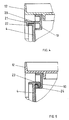
- leaf springs 20 are attached to the frame 10, the free ends of which are shaped into hooks 21 which cover the upper edge of the end wall 4.
- the end of the leaf spring provided with the hook 21 is shaped in such a way that an engagement surface 22 can be found with the hand or a finger in order to be able to push the hook 21 upward and the end face wall 4 can thereby pivot outwards.
- the end wall must not and must not be closable.
- the flap 4 and the lid 12 can be sealed to the upper frame 10 if a projection 25 with a hole 26 is provided on the upper frame 10 and another hole 28 is provided on the flap 4 and another hole 29 in the lid 12. A wire is then drawn through these holes 26, 28, 29, which is secured with a seal. For structural reasons, it is advantageous to provide a recess 30 above the projection 27, through which the projection 25 can pass.
Landscapes
- Engineering & Computer Science (AREA)
- Mechanical Engineering (AREA)
- Rigid Containers With Two Or More Constituent Elements (AREA)
Applications Claiming Priority (2)
| Application Number | Priority Date | Filing Date | Title |
|---|---|---|---|
| DE4311142 | 1993-04-05 | ||
| DE19934311142 DE4311142C2 (de) | 1993-04-05 | 1993-04-05 | Transportkasten |
Publications (2)
| Publication Number | Publication Date |
|---|---|
| EP0619237A2 true EP0619237A2 (fr) | 1994-10-12 |
| EP0619237A3 EP0619237A3 (fr) | 1995-04-05 |
Family
ID=6484778
Family Applications (1)
| Application Number | Title | Priority Date | Filing Date |
|---|---|---|---|
| EP94104272A Ceased EP0619237A3 (fr) | 1993-04-05 | 1994-03-18 | Caisse de transport. |
Country Status (2)
| Country | Link |
|---|---|
| EP (1) | EP0619237A3 (fr) |
| DE (1) | DE4311142C2 (fr) |
Cited By (3)
| Publication number | Priority date | Publication date | Assignee | Title |
|---|---|---|---|---|
| ES2131998A1 (es) * | 1993-11-19 | 1999-08-01 | Steiner Freizeitmoebel Gmbh | Caja para transporte y almacenamiento |
| EP1442987A3 (fr) * | 2003-02-01 | 2004-10-27 | Fritz Schäfer GmbH | Recipient de transport et de stockage |
| CN109305523A (zh) * | 2018-10-29 | 2019-02-05 | 中车戚墅堰机车有限公司 | 一种机车用的移动机构 |
Families Citing this family (4)
| Publication number | Priority date | Publication date | Assignee | Title |
|---|---|---|---|---|
| DE29701203U1 (de) * | 1997-01-24 | 1998-06-25 | Koordination Globus Betriebe GmbH & Co. KG, 66606 St Wendel | Haushaltskühlbox |
| DE20019462U1 (de) | 2000-11-13 | 2001-02-01 | SAI Automotive SAL GmbH, 76744 Wörth | Klappbehältereinrichtung |
| DE10216988A1 (de) * | 2002-04-16 | 2003-10-30 | Rene Stern | Versorgungsbox |
| CN105620861B (zh) * | 2016-02-04 | 2017-08-29 | 浙江双友物流器械股份有限公司 | 一种可折叠式货箱 |
Family Cites Families (6)
| Publication number | Priority date | Publication date | Assignee | Title |
|---|---|---|---|---|
| DE1693496U (de) * | 1953-09-09 | 1955-02-17 | Walther Dipl Ing Zarges | Zusammenlegbarer transportbehaelter. |
| US4798304A (en) * | 1987-10-08 | 1989-01-17 | Monoflo International, Inc. | Collapsible box |
| GB2214903B (en) * | 1988-02-25 | 1991-12-18 | Ind Tech Res Inst | Collapsible container |
| ATE153948T1 (de) * | 1992-03-31 | 1997-06-15 | Schaefer Gmbh Fritz | Zusammenlegbarer lager- und transportkasten |
| DE4229802C2 (de) * | 1992-09-09 | 1996-09-19 | Stucki Kunststoffwerk | Transportkasten aus Kunststoff |
| DE9303740U1 (de) * | 1993-03-13 | 1993-07-15 | Walther Faltsysteme GmbH, 4330 Mülheim | Faltbarer Transport- und Lagerbehälter |
-
1993
- 1993-04-05 DE DE19934311142 patent/DE4311142C2/de not_active Expired - Fee Related
-
1994
- 1994-03-18 EP EP94104272A patent/EP0619237A3/fr not_active Ceased
Cited By (4)
| Publication number | Priority date | Publication date | Assignee | Title |
|---|---|---|---|---|
| ES2131998A1 (es) * | 1993-11-19 | 1999-08-01 | Steiner Freizeitmoebel Gmbh | Caja para transporte y almacenamiento |
| EP1442987A3 (fr) * | 2003-02-01 | 2004-10-27 | Fritz Schäfer GmbH | Recipient de transport et de stockage |
| EP1690798A1 (fr) | 2003-02-01 | 2006-08-16 | Fritz Schäfer GmbH | Récipient de transport et de stockage |
| CN109305523A (zh) * | 2018-10-29 | 2019-02-05 | 中车戚墅堰机车有限公司 | 一种机车用的移动机构 |
Also Published As
| Publication number | Publication date |
|---|---|
| DE4311142A1 (de) | 1994-10-06 |
| EP0619237A3 (fr) | 1995-04-05 |
| DE4311142C2 (de) | 1995-03-09 |
Similar Documents
| Publication | Publication Date | Title |
|---|---|---|
| DE3347367C2 (fr) | ||
| DE10041886B4 (de) | Transportbehälter | |
| DE2734964C2 (de) | Zusammenklappbarer Transportkasten | |
| EP1442987A2 (fr) | Récipient de transport et de stockage | |
| DE3101975A1 (de) | Verpackung fuer eine vielzahl von ausstellungspackungen | |
| DE2252831A1 (de) | Behaelter | |
| EP0619237A2 (fr) | Caisse de transport | |
| EP0508461A1 (fr) | Casiers empilables pour atelier | |
| EP2571775A1 (fr) | Contenant de transport en plastique, en particulier caisse de transport | |
| EP0586822A2 (fr) | Caisse de transport en matière plastique | |
| DE4228949C2 (de) | Transportkasten aus Kunststoff | |
| DE4322479A1 (de) | Transportkasten aus Kunststoff | |
| CH679659A5 (fr) | ||
| EP0810156B1 (fr) | Boíte pliable | |
| EP0336067A1 (fr) | Conteneur pour rouleaux,bobines ou similaires | |
| DE4223460C2 (de) | Einsteck-Gebinde-Box | |
| DE9211696U1 (de) | Transportkasten aus Kunststoff | |
| DE69205012T2 (de) | Faltpackung vom boxpalettentyp. | |
| EP0585566A2 (fr) | Caisse de transport en matière plastique | |
| CH709990A2 (de) | Lager- und Transportbehälter mit mindestens einem Wandelement, das eine Öffnungsvorrichtung aufweist. | |
| DE9411769U1 (de) | Stapelbarer Karton | |
| DE102013000296A1 (de) | Großbehälter mit vorzugsweise palettenartigem Bodenteil | |
| DE4308868A1 (de) | Transportkasten | |
| DE2525207A1 (de) | Lager- und transportbehaelter | |
| DE20017500U1 (de) | Faltkarton mit einer Palette |
Legal Events
| Date | Code | Title | Description |
|---|---|---|---|
| PUAI | Public reference made under article 153(3) epc to a published international application that has entered the european phase |
Free format text: ORIGINAL CODE: 0009012 |
|
| AK | Designated contracting states |
Kind code of ref document: A2 Designated state(s): AT BE CH DE ES FR GB IT LI NL SE |
|
| PUAL | Search report despatched |
Free format text: ORIGINAL CODE: 0009013 |
|
| AK | Designated contracting states |
Kind code of ref document: A3 Designated state(s): AT BE CH DE ES FR GB IT LI NL SE |
|
| 17P | Request for examination filed |
Effective date: 19950526 |
|
| GRAG | Despatch of communication of intention to grant |
Free format text: ORIGINAL CODE: EPIDOS AGRA |
|
| 17Q | First examination report despatched |
Effective date: 19960722 |
|
| STAA | Information on the status of an ep patent application or granted ep patent |
Free format text: STATUS: THE APPLICATION HAS BEEN REFUSED |
|
| 18R | Application refused |
Effective date: 19970123 |