EP0619399A1 - Verfahren und Vorrichtung zur öffnung des Pressspaltes in einer Langspaltpresse - Google Patents
Verfahren und Vorrichtung zur öffnung des Pressspaltes in einer Langspaltpresse Download PDFInfo
- Publication number
- EP0619399A1 EP0619399A1 EP94850042A EP94850042A EP0619399A1 EP 0619399 A1 EP0619399 A1 EP 0619399A1 EP 94850042 A EP94850042 A EP 94850042A EP 94850042 A EP94850042 A EP 94850042A EP 0619399 A1 EP0619399 A1 EP 0619399A1
- Authority
- EP
- European Patent Office
- Prior art keywords
- roll
- nip
- extended
- glide
- flange part
- Prior art date
- Legal status (The legal status is an assumption and is not a legal conclusion. Google has not performed a legal analysis and makes no representation as to the accuracy of the status listed.)
- Granted
Links
- 238000000034 method Methods 0.000 title claims abstract description 15
- 238000010276 construction Methods 0.000 description 5
- XLYOFNOQVPJJNP-UHFFFAOYSA-N water Substances O XLYOFNOQVPJJNP-UHFFFAOYSA-N 0.000 description 4
- 230000006835 compression Effects 0.000 description 2
- 238000007906 compression Methods 0.000 description 2
- 238000007789 sealing Methods 0.000 description 2
- 238000010438 heat treatment Methods 0.000 description 1
- 230000006698 induction Effects 0.000 description 1
- 230000001050 lubricating effect Effects 0.000 description 1
- 230000005855 radiation Effects 0.000 description 1
- 238000000926 separation method Methods 0.000 description 1
- 230000003685 thermal hair damage Effects 0.000 description 1
Images



Classifications
-
- D—TEXTILES; PAPER
- D21—PAPER-MAKING; PRODUCTION OF CELLULOSE
- D21F—PAPER-MAKING MACHINES; METHODS OF PRODUCING PAPER THEREON
- D21F3/00—Press section of machines for making continuous webs of paper
- D21F3/02—Wet presses
- D21F3/0209—Wet presses with extended press nip
- D21F3/0218—Shoe presses
- D21F3/0227—Belts or sleeves therefor
- D21F3/0245—Means for fixing the sleeve to the roller end
-
- D—TEXTILES; PAPER
- D21—PAPER-MAKING; PRODUCTION OF CELLULOSE
- D21F—PAPER-MAKING MACHINES; METHODS OF PRODUCING PAPER THEREON
- D21F3/00—Press section of machines for making continuous webs of paper
- D21F3/02—Wet presses
- D21F3/0209—Wet presses with extended press nip
- D21F3/0218—Shoe presses
-
- D—TEXTILES; PAPER
- D21—PAPER-MAKING; PRODUCTION OF CELLULOSE
- D21G—CALENDERS; ACCESSORIES FOR PAPER-MAKING MACHINES
- D21G1/00—Calenders; Smoothing apparatus
- D21G1/02—Rolls; Their bearings
- D21G1/0206—Controlled deflection rolls
- D21G1/0213—Controlled deflection rolls with deflection compensation means acting between the roller shell and its supporting member
- D21G1/022—Controlled deflection rolls with deflection compensation means acting between the roller shell and its supporting member the means using fluid pressure
Definitions
- the invention concerns a method for opening a nip in an extended-nip press and equipment for opening a nip in an extended-nip press.
- the press felt and the glide-belt mantle may be damaged if the press has to be stopped out of some reason because of a disturbance in running.
- the temperature of the water in a hot-water heated back-up roll is 140°C and the surface temperature is about 80°C during running, after stopping the surface temperature rises to about 120°C.
- an opening method is described in which an eccentric end of the extended-nip press roll is rotated after a movement of opening of the press shoe so that the belt mantle is shifted apart from the back-up roll.
- the guide rolls of the felt loop may also be displaceable so that the contact of the felt with a hot roll is separated.
- the method and equipment of opening that are employed herein facilitate replacements of felt and glide-belt mantle and make the replacements quicker.
- the method in accordance with the invention is mainly characterized in that, when the nip between the rolls is opened, the loading shoe of the loading members of the extended-nip roll is shifted to an open position and apart from the glide-belt mantle, and that, in the method, the inside end-flange part of the end flange, which is operationally coupled with the bearing means of the glide-belt mantle, is rotated as parallel to the face of the central axle of the roll, whereby the glide-belt mantle is separated from contact with the back-up roll as the central axis of the end-flange part is placed at a distance from the central axis of the roll.
- the equipment in accordance with the invention is mainly characterized in that the closed resilient glide-belt mantle of the extended-nip press roll is, at its edges, attached to the end-flange part of the end flange, which end-flange part is further fitted to revolve on support of bearing means, said bearing means being placed between said outside end-flange part and an inner end-flange part, and that the end-flange part is fitted so that its central axis is placed eccentrically in relation to the central axis of the axle of the extended-nip press roll, in which case, by rotating the end-flange part, the eccentricity of said end-flange part is utilized, whereby, by means of rotation of the part, the glide-belt mantle can be shifted into different positions in relation to the back-up roll, apart from the back-up roll or into contact with the back-up roll.
- the extended-nip press in accordance with the invention comprises an extended nip for a paper or board web.
- the arrangement of equipment comprises a press member, which can be pressed with a force against the back-up roll, which back-up roll is preferably heated.
- the back-up roll may also be a non-heated roll.
- the displaceable press member is preferably a press shoe, which can be pressed with the force of the loading-cylinder means against the heated back-up roll.
- the arrangement of equipment comprises an endless felt H, which is passed through the press zone and which receives water, said felt being arranged to run through the press zone together with the fibrous web W to be dewatered.
- the solution of equipment comprises a closed glide-belt mantle of the extended-nip roll, which belt mantle is passed through the press zone, the web being passed through the nip area between the felt and the back-up roll.
- the arrangement of equipment may also comprise two felts, between which the web is carried and pressed.
- Figure 1 shows an extended-nip press equipment of a paper machine.
- Figure 2 shows an assembly of equipment in accordance with the invention viewed in the machine direction.
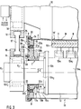
- Figure 3 shows one end area of the roll assembly in accordance with the invention as shown in Fig. 2.
- Figure 4 shows an arrangement of equipment in which the positions of the felt guide rolls and of the blow boxes can be displaced, in which case the felt can also be separated from the heated upper back-up roll.
- Fig. 1 shows an equipment of an extended-nip press in a paper machine.
- the web W is passed into a nip N between a lower extended-nip press roll 11 and a heated back-up roll 10 between the felt H and the roll face 10' of the back-up roll 10.
- Fig. 2 shows the rolls 10 and 11 of Fig. 1 as viewed in the machine direction.
- the extended nip between the rolls 10 and 11 is denoted with the reference arrow N in the figure.
- the felt H and the web W are passed through the nip N.
- the roll 10 is a heated back-up roll
- the roll 11 is an extended-nip roll, which comprises loading means 12a1, 12a2... and in which the loading means 12a1,12a2..., preferably cylinder means, in the central axle 13 are fitted to act with a force upon the loading or glide shoe 12b and further, through the flexible closed glide-belt mantle F, upon the web W to dewater the web.
- the web W is understood as referring to a paper or board web.
- the lower extended-nip press roll 11 comprises a flexible closed glide-belt mantle F, which is fitted to run along the face of the loading shoe or glide shoe 12b, an oil medium being passed into the space between the glide shoe 12b and the closed glide-belt mantle F as a lubricating medium.
- the back-up roll 10 is preferably a roll that is heated by means of an inside heating medium, such as water, steam or oil, or externally, e.g., by means of induction or infrared radiation.
- the back-up roll 10 may also be a non-heated roll.
- Fig. 3 shows one side of the rolls 10,11 on an enlarged scale.
- the equipment comprises a heated back-up roll 10 and an extended-nip press roll 11 jointly operative with said back-up roll, the paper web W, the felt H, and the glide-belt mantle F of the roll 11 being passed through the nip N between said rolls.
- the extended-nip press 11 comprises loading means 12, which consist of actuators 12a1,12a2...12a n , preferably of hydraulic cylinders, by whose means the glide shoe 12b is acted upon with a force, being pressed against the back-up roll 10, whereby the web W is subjected to compression between the felt H and the face 10' of the back-up roll 10.
- loading means 12 consist of actuators 12a1,12a2...12a n , preferably of hydraulic cylinders, by whose means the glide shoe 12b is acted upon with a force, being pressed against the back-up roll 10, whereby the web W is subjected to compression between the felt H and the face 10' of the back-up roll 10.
- the extended-nip press roll 11 comprises a stationary non-revolving central axle 13, which comprises a central-axle portion 13a1 in the middle and lateral axle portions 13a2 and 13a3 of smaller diameter.
- a flange 13b is formed between the axle portions 13a1 and 13a2.
- the extended-nip press roll 11 is suspended by means of its central axle 13, by the ends of the axle, on bearing means 14, which permit a certain deflection and angular change for the axle 13 in a loading situation.
- the bearing housing 15 of the bearing means 14 or the related constructions are coupled with the bearing housing 16 of the bearing means 18 of the roll 10 or with a related construction by means of a tie bar 17 or equivalent.
- the roll 10 is journalled as revolving by means of bearing means 18.
- the flange 13b is coupled with one or several actuators 19, preferably cylinder devices, which comprise a cylinder body 19a, a cylinder rod 19b, and, at its end, a roller or a glide piece 19c, which is fitted to run in the groove M in the shoulder 20b' of the end flange 20b.
- the actuator/actuators 19 By means of the actuator/actuators 19, the glide-belt mantle F is tensioned by acting upon the end flanges 20 with a force, which end flanges are fitted to glide on the axle portions 13a2.
- the actuator construction 19 may be similar at both ends of the roll.
- the end flange 20 comprises a first end-flange part 20a and a second end-flange part 20b, which is placed inside the first end-flange part 20a. Between the end-flange parts 20a and 20b, there are journalling means 21 and sealing members 21a. The end-flange part 20b can be made to glide on the axle portion 13a2. Thereby, rotation of the end-flange part 20b in relation to the axle 13 is permitted.
- the bearing means 21 are fitted between the flange parts 20a,20b, and they are held in their positions by means of covers 22a,22b. During operation, the glide-belt mantle F is rotated on bearing means 21.
- the end flange 20 is fitted to glide on the face C of the axle portion 13a2.
- the seal 23 is fitted at the side edge of the end-flange part 20b.
- the seal is fitted to glide against the face C.
- the glide-belt mantle F is tensioned between the end flanges 20 in the way described above.
- the glide-belt mantle F is attached to the end-flange part 20a by means of wedge-ring segments 24 and by means of fastening-ring segments 25 fitted at the outer edge of the end-flange part 20a.
- the wedge-ring segments 24 are fitted in the fastening-ring segments 25 between the shoulder 26 and the outer face D of the end-flange part 20a.
- the glide-belt mantle F is tensioned by its ends against the outer face D of the end-flange part 20a by pressing the wedge-ring segments 24 by means of a screw device R tightly towards the bottom of their fastening groove U. In this way, by means of the wedge-ring segments 24, a sealing force is applied to the glide-belt mantle F, and the mantle is kept tightly against the outer face D of the end-flange part 20a.
- the axis of rotation and central axis of the outer end-flange part 20a of the end flange 20 in the construction in accordance with the invention is denoted with X2.
- the central axis of the end-flange part 20b is also X2.
- the central axis of the axle 13 of the extended-nip roll 11 is denoted with X1.
- the distance E between the axes X2 and X1 is the eccentricity of the end-flange part 20b.
- the inner flange part 20b of the end flange 20 is rotated around the axis X1.
- the inner end-flange part 20b is rotated by means of an actuator 30 as parallel to the face C of the axle portion 13a2 of the axle 13, in which case, owing to the difference in distance between the above axes X1 and X2, i.e. owing to the eccentricity E, the glide-belt mantle F is shifted apart from the heated back-up roll 10.
- the actuator 30 is preferably a hydraulic cylinder, which is provided with articulated joints both at the end of the cylinder rod and at the end of the cylinder body.
- Fig. 3 includes a sectional view of the piston rod of the cylinder 30.
- Figure 4 illustrates the arrangement of equipment in accordance with the invention, wherein, in a situation of opening the nip N, the felt H can also be brought apart from the heated back-up roll 10. Separation of the felt H from the back-up roll 10 is necessary especially in extended-nip constructions in which the back-up roll 10 is expressly a heated roll.
- the blow box 35 and the felt-guide rolls 40 and 50 are fitted to be displaceable by means of actuators S1,S2 and S3 into different positions, downwards as shown n the figure, in which case the felt H can be separated from the back-up roll 10 (Fig. 4 illustrates the actuators).
- an angle of rotation of about 45° is sufficient for the flange 20b to separate the glide-belt flange from the outer face 10' of the heated roll mantle 10.
- the actuator 30 is preferably a cylinder device.
- two different operating positions of the cylinder device 30 are illustrated with dashed-dotted lines.
- the glide-belt mantle F is in the operating position and placed against the roll 10.
- the end-flange part 20b of the end flange 20 has been rotated through the angle ⁇ (about 80°), whereby, owing to the eccentricity E of the end-flange part 20b, the glide-belt mantle F has been shifted apart from the roll 10.
- the extent of opening must be about 20...60 mm.
Landscapes
- Physics & Mathematics (AREA)
- Fluid Mechanics (AREA)
- Paper (AREA)
- Press Drives And Press Lines (AREA)
- Coating With Molten Metal (AREA)
- Casting Or Compression Moulding Of Plastics Or The Like (AREA)
- Rolls And Other Rotary Bodies (AREA)
- Control And Other Processes For Unpacking Of Materials (AREA)
Applications Claiming Priority (2)
| Application Number | Priority Date | Filing Date | Title |
|---|---|---|---|
| FI931321 | 1993-03-24 | ||
| FI931321A FI96046C (fi) | 1993-03-24 | 1993-03-24 | Pitkänippipuristimen nipin avausmenetelmä ja laitteisto pitkänippipuristimen nipin avaamiseksi |
Publications (2)
| Publication Number | Publication Date |
|---|---|
| EP0619399A1 true EP0619399A1 (de) | 1994-10-12 |
| EP0619399B1 EP0619399B1 (de) | 1997-05-21 |
Family
ID=8537623
Family Applications (1)
| Application Number | Title | Priority Date | Filing Date |
|---|---|---|---|
| EP94850042A Expired - Lifetime EP0619399B1 (de) | 1993-03-24 | 1994-03-23 | Verfahren und Vorrichtung zur Öffnung des Press-Spaltes in einer Langspaltpresse |
Country Status (6)
| Country | Link |
|---|---|
| US (1) | US5496442A (de) |
| EP (1) | EP0619399B1 (de) |
| AT (1) | ATE153401T1 (de) |
| CA (1) | CA2117215C (de) |
| DE (1) | DE69403263T2 (de) |
| FI (1) | FI96046C (de) |
Cited By (8)
| Publication number | Priority date | Publication date | Assignee | Title |
|---|---|---|---|---|
| DE29702362U1 (de) * | 1996-04-29 | 1997-05-15 | Voith Sulzer Papiermaschinen GmbH, 89522 Heidenheim | Preßwalze |
| EP1285990A1 (de) * | 2001-08-14 | 2003-02-26 | Eduard Küsters Maschinenfabrik GmbH & Co. KG | Vorrichtung zum Bilden eines Langspalts |
| EP1291462A1 (de) * | 2001-09-07 | 2003-03-12 | Eduard Küsters Maschinenfabrik GmbH & Co. KG | Klemmverbindung in einer Langspalt-Presswalze |
| WO2003040472A1 (en) * | 2001-11-06 | 2003-05-15 | Metso Paper, Inc. | Arrangement for closing and opening a roll nip in a shoe calender |
| EP1801285A1 (de) | 2005-10-07 | 2007-06-27 | Vaahto OY | Presswalze |
| EP2420617A1 (de) * | 2010-08-17 | 2012-02-22 | Voith Patent GmbH | Kalander |
| CN111851112A (zh) * | 2019-04-29 | 2020-10-30 | 维美德技术有限公司 | 靴式辊端部模块以及靴式辊端部模块的组装方法 |
| CN111851110A (zh) * | 2019-04-29 | 2020-10-30 | 维美德技术有限公司 | 靴式辊端部模块分度 |
Families Citing this family (11)
| Publication number | Priority date | Publication date | Assignee | Title |
|---|---|---|---|---|
| DE4435897C1 (de) * | 1994-10-07 | 1996-01-11 | Voith Sulzer Papiermasch Gmbh | Supportverbindungen |
| US5733415A (en) * | 1996-08-01 | 1998-03-31 | Beloit Technologies, Inc. | Closed shoe press head indexing system |
| FI101319B1 (fi) * | 1996-10-25 | 1998-05-29 | Valmet Corp | Menetelmä ja laitteisto pitkänippitelan hihnavaipan kulumisen vähentämiseksi |
| US6045658A (en) * | 1998-06-03 | 2000-04-04 | Beloit Technologies, Inc. | Extended nip press apparatus |
| US6248210B1 (en) * | 1998-11-13 | 2001-06-19 | Fort James Corporation | Method for maximizing water removal in a press nip |
| FI991272L (fi) * | 1999-06-03 | 2000-12-04 | Valmet Karlstad Ab | Menetelmä ja järjestely paperikoneen kenkäpuristimen/kenkäkalanterin k engän asemoimiseksi |
| HUP0401030A2 (en) * | 2001-02-13 | 2007-12-28 | Pmt Italia Paper Machinery Tec | An anchor device for anchoring a peripheral edge of a press blanket |
| US6582561B2 (en) * | 2001-08-14 | 2003-06-24 | Eduard Kusters Maschinenfabrik Gmbh & Co. Kg | Apparatus for forming an extended nip |
| SE519993C2 (sv) * | 2001-09-06 | 2003-05-06 | Metso Paper Karlstad Ab | Skopress |
| GB2386133B (en) * | 2002-03-08 | 2005-03-16 | Sandusky Walmsley Ltd | Blanket clamping arrangement for shoe press of papermaking machine |
| US20060018577A1 (en) * | 2004-07-20 | 2006-01-26 | Eduard Kusters Maschinenfabrik Gmbh & Co. Kg | Apparatus for forming an extended nip |
Citations (2)
| Publication number | Priority date | Publication date | Assignee | Title |
|---|---|---|---|---|
| GB2182367A (en) * | 1985-10-30 | 1987-05-13 | Escher Wyss Gmbh | Extended nip press |
| DE3735492A1 (de) * | 1986-11-21 | 1988-05-26 | Valmet Oy | Verfahren in einer durchbiegungsgeregelten walze und eine das verfahren anwendende walzenvorrichtung |
Family Cites Families (7)
| Publication number | Priority date | Publication date | Assignee | Title |
|---|---|---|---|---|
| DE3317457A1 (de) * | 1983-05-13 | 1984-11-15 | J.M. Voith Gmbh, 7920 Heidenheim | Presseinrichtung fuer bandfoermiges gut, insbesondere zum entwaessern einer papierbahn |
| DE3503373A1 (de) * | 1985-02-01 | 1986-08-07 | J.M. Voith Gmbh, 7920 Heidenheim | Walzenpresse mit einer langspalt-presswalze |
| DE3708191A1 (de) * | 1987-03-13 | 1988-09-22 | Voith Gmbh J M | Nasspresse |
| DE3832324A1 (de) * | 1988-09-23 | 1990-04-05 | Voith Gmbh J M | Langspalt-presswalze |
| EP0442257B1 (de) * | 1990-01-16 | 1995-05-03 | Valmet Paper Machinery Inc. | Presswalze |
| SE464922B (sv) * | 1990-05-08 | 1991-07-01 | Valmet Paper Machinery Inc | Pressvals |
| DE4113623C1 (de) * | 1991-04-26 | 1992-02-20 | J.M. Voith Gmbh, 7920 Heidenheim, De |
-
1993
- 1993-03-24 FI FI931321A patent/FI96046C/fi active IP Right Grant
-
1994
- 1994-03-07 US US08/207,296 patent/US5496442A/en not_active Expired - Lifetime
- 1994-03-08 CA CA002117215A patent/CA2117215C/en not_active Expired - Fee Related
- 1994-03-23 EP EP94850042A patent/EP0619399B1/de not_active Expired - Lifetime
- 1994-03-23 DE DE69403263T patent/DE69403263T2/de not_active Expired - Fee Related
- 1994-03-23 AT AT94850042T patent/ATE153401T1/de not_active IP Right Cessation
Patent Citations (2)
| Publication number | Priority date | Publication date | Assignee | Title |
|---|---|---|---|---|
| GB2182367A (en) * | 1985-10-30 | 1987-05-13 | Escher Wyss Gmbh | Extended nip press |
| DE3735492A1 (de) * | 1986-11-21 | 1988-05-26 | Valmet Oy | Verfahren in einer durchbiegungsgeregelten walze und eine das verfahren anwendende walzenvorrichtung |
Cited By (12)
| Publication number | Priority date | Publication date | Assignee | Title |
|---|---|---|---|---|
| DE29702362U1 (de) * | 1996-04-29 | 1997-05-15 | Voith Sulzer Papiermaschinen GmbH, 89522 Heidenheim | Preßwalze |
| EP1285990A1 (de) * | 2001-08-14 | 2003-02-26 | Eduard Küsters Maschinenfabrik GmbH & Co. KG | Vorrichtung zum Bilden eines Langspalts |
| EP1291462A1 (de) * | 2001-09-07 | 2003-03-12 | Eduard Küsters Maschinenfabrik GmbH & Co. KG | Klemmverbindung in einer Langspalt-Presswalze |
| WO2003040472A1 (en) * | 2001-11-06 | 2003-05-15 | Metso Paper, Inc. | Arrangement for closing and opening a roll nip in a shoe calender |
| EP1801285A1 (de) | 2005-10-07 | 2007-06-27 | Vaahto OY | Presswalze |
| EP2420617A1 (de) * | 2010-08-17 | 2012-02-22 | Voith Patent GmbH | Kalander |
| CN111851112A (zh) * | 2019-04-29 | 2020-10-30 | 维美德技术有限公司 | 靴式辊端部模块以及靴式辊端部模块的组装方法 |
| CN111851110A (zh) * | 2019-04-29 | 2020-10-30 | 维美德技术有限公司 | 靴式辊端部模块分度 |
| EP3733962A1 (de) * | 2019-04-29 | 2020-11-04 | Valmet Technologies Oy | Schuhwalzenendmodul |
| EP3733961A1 (de) * | 2019-04-29 | 2020-11-04 | Valmet Technologies Oy | Schuhwalzenendmodul und verfahren zum zusammenbau eines schuhwalzenendmoduls |
| CN111851112B (zh) * | 2019-04-29 | 2022-07-26 | 维美德技术有限公司 | 靴式辊端部模块以及靴式辊端部模块的组装方法 |
| CN111851110B (zh) * | 2019-04-29 | 2022-07-26 | 维美德技术有限公司 | 靴式辊端部模块分度 |
Also Published As
| Publication number | Publication date |
|---|---|
| ATE153401T1 (de) | 1997-06-15 |
| FI96046B (fi) | 1996-01-15 |
| US5496442A (en) | 1996-03-05 |
| FI96046C (fi) | 1996-04-25 |
| FI931321L (fi) | 1994-09-25 |
| CA2117215A1 (en) | 1994-09-25 |
| DE69403263T2 (de) | 1997-10-09 |
| DE69403263D1 (de) | 1997-06-26 |
| CA2117215C (en) | 2004-12-14 |
| EP0619399B1 (de) | 1997-05-21 |
| FI931321A0 (fi) | 1993-03-24 |
Similar Documents
| Publication | Publication Date | Title |
|---|---|---|
| EP0619399B1 (de) | Verfahren und Vorrichtung zur Öffnung des Press-Spaltes in einer Langspaltpresse | |
| US5368697A (en) | Press section of a paper machine with stone roll and elastic press element | |
| US5043046A (en) | Extended nip-press | |
| US3783097A (en) | Hydrodynamically loaded web press with slipper bearing shoes | |
| SU1072821A3 (ru) | Пресс с удлиненным захватом дл прессовой части бумагоделательной машины | |
| US5092962A (en) | Hot-pressing and drying device | |
| FI99035C (fi) | Paperikoneen imutelan tiivisterakenne | |
| KR950018943A (ko) | 확장닙 압착부가 사용되는 제지기계 압착부 | |
| US4788779A (en) | Method and apparatus for the rapid consolidation and/or drying of moist porous webs | |
| CN1043548A (zh) | 可控中高辊支承装置 | |
| US5693186A (en) | Method and apparatus for interconnecting rolls in an extended-nip press | |
| KR100228925B1 (ko) | 제지기계에서 이퀄라이징 프레스가 장치된 프레스부 및 프레스 방법 | |
| EP0147352B1 (de) | Nasspresse mit verlängerter Presszone | |
| EP1605096B1 (de) | Schuhpresse | |
| US6010443A (en) | Clamping ring for an enclosed shoe press | |
| EP0107607A2 (de) | Nasspresse mit verlängerter Presszone | |
| US5904813A (en) | Press roll with jacket edge clamping ring | |
| WO1999051812A1 (en) | Seal construction for a suction box in a suction roll | |
| US6899023B2 (en) | Extended-nip roll press for dewatering a fibrous web | |
| US5850785A (en) | Coupling construction between an extended-nip roll and a backup roll | |
| FI114031B (fi) | Menetelmä paperirainan puristamiseksi ja paperirainan puristuslaite | |
| NZ234490A (en) | Extended nip press belt having liquid extraction channels in its outer surface | |
| US5154799A (en) | Method and device in a compact press section of a paper machine for replacement of rolls and fabrics | |
| FI77927B (fi) | Mekanisk torkpress med kontinuerlig drift. | |
| EP0227302A1 (de) | Mittel zur Steuerung der Durchbiegung einer Walze |
Legal Events
| Date | Code | Title | Description |
|---|---|---|---|
| PUAI | Public reference made under article 153(3) epc to a published international application that has entered the european phase |
Free format text: ORIGINAL CODE: 0009012 |
|
| AK | Designated contracting states |
Kind code of ref document: A1 Designated state(s): AT DE FR GB IT SE |
|
| 17P | Request for examination filed |
Effective date: 19941130 |
|
| 17Q | First examination report despatched |
Effective date: 19950809 |
|
| RAP1 | Party data changed (applicant data changed or rights of an application transferred) |
Owner name: VALMET CORPORATION |
|
| GRAG | Despatch of communication of intention to grant |
Free format text: ORIGINAL CODE: EPIDOS AGRA |
|
| GRAH | Despatch of communication of intention to grant a patent |
Free format text: ORIGINAL CODE: EPIDOS IGRA |
|
| GRAH | Despatch of communication of intention to grant a patent |
Free format text: ORIGINAL CODE: EPIDOS IGRA |
|
| GRAA | (expected) grant |
Free format text: ORIGINAL CODE: 0009210 |
|
| AK | Designated contracting states |
Kind code of ref document: B1 Designated state(s): AT DE FR GB IT SE |
|
| REF | Corresponds to: |
Ref document number: 153401 Country of ref document: AT Date of ref document: 19970615 Kind code of ref document: T |
|
| REF | Corresponds to: |
Ref document number: 69403263 Country of ref document: DE Date of ref document: 19970626 |
|
| ET | Fr: translation filed | ||
| PLBE | No opposition filed within time limit |
Free format text: ORIGINAL CODE: 0009261 |
|
| STAA | Information on the status of an ep patent application or granted ep patent |
Free format text: STATUS: NO OPPOSITION FILED WITHIN TIME LIMIT |
|
| 26N | No opposition filed | ||
| REG | Reference to a national code |
Ref country code: GB Ref legal event code: IF02 |
|
| PGFP | Annual fee paid to national office [announced via postgrant information from national office to epo] |
Ref country code: SE Payment date: 20080313 Year of fee payment: 15 Ref country code: IT Payment date: 20080321 Year of fee payment: 15 Ref country code: GB Payment date: 20080320 Year of fee payment: 15 |
|
| PGFP | Annual fee paid to national office [announced via postgrant information from national office to epo] |
Ref country code: AT Payment date: 20080314 Year of fee payment: 15 |
|
| PGFP | Annual fee paid to national office [announced via postgrant information from national office to epo] |
Ref country code: FR Payment date: 20080314 Year of fee payment: 15 Ref country code: DE Payment date: 20080321 Year of fee payment: 15 |
|
| PG25 | Lapsed in a contracting state [announced via postgrant information from national office to epo] |
Ref country code: AT Free format text: LAPSE BECAUSE OF NON-PAYMENT OF DUE FEES Effective date: 20090323 |
|
| EUG | Se: european patent has lapsed | ||
| GBPC | Gb: european patent ceased through non-payment of renewal fee |
Effective date: 20090323 |
|
| REG | Reference to a national code |
Ref country code: FR Ref legal event code: ST Effective date: 20091130 |
|
| PG25 | Lapsed in a contracting state [announced via postgrant information from national office to epo] |
Ref country code: DE Free format text: LAPSE BECAUSE OF NON-PAYMENT OF DUE FEES Effective date: 20091001 |
|
| PG25 | Lapsed in a contracting state [announced via postgrant information from national office to epo] |
Ref country code: GB Free format text: LAPSE BECAUSE OF NON-PAYMENT OF DUE FEES Effective date: 20090323 Ref country code: FR Free format text: LAPSE BECAUSE OF NON-PAYMENT OF DUE FEES Effective date: 20091123 |
|
| PG25 | Lapsed in a contracting state [announced via postgrant information from national office to epo] |
Ref country code: IT Free format text: LAPSE BECAUSE OF NON-PAYMENT OF DUE FEES Effective date: 20090323 |
|
| PG25 | Lapsed in a contracting state [announced via postgrant information from national office to epo] |
Ref country code: SE Free format text: LAPSE BECAUSE OF NON-PAYMENT OF DUE FEES Effective date: 20090324 |