EP0619405A1 - Schutz- oder Verstärkungssystem für Trennwandsockeln in Industriegebäuden - Google Patents
Schutz- oder Verstärkungssystem für Trennwandsockeln in Industriegebäuden Download PDFInfo
- Publication number
- EP0619405A1 EP0619405A1 EP94460009A EP94460009A EP0619405A1 EP 0619405 A1 EP0619405 A1 EP 0619405A1 EP 94460009 A EP94460009 A EP 94460009A EP 94460009 A EP94460009 A EP 94460009A EP 0619405 A1 EP0619405 A1 EP 0619405A1
- Authority
- EP
- European Patent Office
- Prior art keywords
- modules
- groove
- ground
- envelope
- base
- Prior art date
- Legal status (The legal status is an assumption and is not a legal conclusion. Google has not performed a legal analysis and makes no representation as to the accuracy of the status listed.)
- Ceased
Links
- 238000005192 partition Methods 0.000 title claims abstract description 33
- 230000002787 reinforcement Effects 0.000 title claims description 9
- 239000000463 material Substances 0.000 claims abstract description 7
- 239000006260 foam Substances 0.000 claims abstract description 5
- 238000007789 sealing Methods 0.000 claims description 8
- 229910001220 stainless steel Inorganic materials 0.000 claims description 5
- 239000010935 stainless steel Substances 0.000 claims description 5
- 238000003466 welding Methods 0.000 claims description 5
- 238000004519 manufacturing process Methods 0.000 claims description 4
- 239000004568 cement Substances 0.000 claims description 3
- 239000011347 resin Substances 0.000 claims description 3
- 229920005989 resin Polymers 0.000 claims description 3
- 238000004078 waterproofing Methods 0.000 claims description 3
- 238000004873 anchoring Methods 0.000 claims 1
- 230000001681 protective effect Effects 0.000 abstract description 2
- 230000003014 reinforcing effect Effects 0.000 abstract 1
- 238000009434 installation Methods 0.000 description 8
- 238000000034 method Methods 0.000 description 5
- 239000002184 metal Substances 0.000 description 4
- 229910052751 metal Inorganic materials 0.000 description 4
- 229910000746 Structural steel Inorganic materials 0.000 description 3
- 239000000945 filler Substances 0.000 description 3
- 239000004793 Polystyrene Substances 0.000 description 2
- 238000010276 construction Methods 0.000 description 2
- 238000009415 formwork Methods 0.000 description 2
- 229920002223 polystyrene Polymers 0.000 description 2
- XLYOFNOQVPJJNP-UHFFFAOYSA-N water Substances O XLYOFNOQVPJJNP-UHFFFAOYSA-N 0.000 description 2
- 102000000591 Tight Junction Proteins Human genes 0.000 description 1
- 108010002321 Tight Junction Proteins Proteins 0.000 description 1
- 239000000853 adhesive Substances 0.000 description 1
- 230000001070 adhesive effect Effects 0.000 description 1
- 239000011324 bead Substances 0.000 description 1
- 238000004140 cleaning Methods 0.000 description 1
- 238000005553 drilling Methods 0.000 description 1
- 229920001971 elastomer Polymers 0.000 description 1
- 230000005611 electricity Effects 0.000 description 1
- 238000002513 implantation Methods 0.000 description 1
- 239000011810 insulating material Substances 0.000 description 1
- 238000009413 insulation Methods 0.000 description 1
- 239000012212 insulator Substances 0.000 description 1
- 239000004570 mortar (masonry) Substances 0.000 description 1
- 229920001296 polysiloxane Polymers 0.000 description 1
- 229920002635 polyurethane Polymers 0.000 description 1
- 239000004814 polyurethane Substances 0.000 description 1
- 238000009418 renovation Methods 0.000 description 1
- 230000035939 shock Effects 0.000 description 1
- 239000004590 silicone sealant Substances 0.000 description 1
- 210000001578 tight junction Anatomy 0.000 description 1
- 238000005406 washing Methods 0.000 description 1
Images


Classifications
-
- E—FIXED CONSTRUCTIONS
- E04—BUILDING
- E04H—BUILDINGS OR LIKE STRUCTURES FOR PARTICULAR PURPOSES; SWIMMING OR SPLASH BATHS OR POOLS; MASTS; FENCING; TENTS OR CANOPIES, IN GENERAL
- E04H5/00—Buildings or groups of buildings for industrial or agricultural purposes
- E04H5/10—Buildings forming part of cooling plants
-
- E—FIXED CONSTRUCTIONS
- E04—BUILDING
- E04F—FINISHING WORK ON BUILDINGS, e.g. STAIRS, FLOORS
- E04F19/00—Other details of constructional parts for finishing work on buildings
- E04F19/02—Borders; Finishing strips, e.g. beadings; Light coves
- E04F19/04—Borders; Finishing strips, e.g. beadings; Light coves for use between floor or ceiling and wall, e.g. skirtings
-
- E—FIXED CONSTRUCTIONS
- E04—BUILDING
- E04F—FINISHING WORK ON BUILDINGS, e.g. STAIRS, FLOORS
- E04F19/00—Other details of constructional parts for finishing work on buildings
- E04F19/02—Borders; Finishing strips, e.g. beadings; Light coves
- E04F19/026—Borders; Finishing strips, e.g. beadings; Light coves specially adapted for cushioning impacts
-
- E—FIXED CONSTRUCTIONS
- E04—BUILDING
- E04F—FINISHING WORK ON BUILDINGS, e.g. STAIRS, FLOORS
- E04F19/00—Other details of constructional parts for finishing work on buildings
- E04F19/02—Borders; Finishing strips, e.g. beadings; Light coves
- E04F19/04—Borders; Finishing strips, e.g. beadings; Light coves for use between floor or ceiling and wall, e.g. skirtings
- E04F19/045—Hygienic or watertight plinths
-
- E—FIXED CONSTRUCTIONS
- E04—BUILDING
- E04F—FINISHING WORK ON BUILDINGS, e.g. STAIRS, FLOORS
- E04F19/00—Other details of constructional parts for finishing work on buildings
- E04F19/02—Borders; Finishing strips, e.g. beadings; Light coves
- E04F19/04—Borders; Finishing strips, e.g. beadings; Light coves for use between floor or ceiling and wall, e.g. skirtings
- E04F2019/0404—Borders; Finishing strips, e.g. beadings; Light coves for use between floor or ceiling and wall, e.g. skirtings characterised by the material
- E04F2019/0422—Borders; Finishing strips, e.g. beadings; Light coves for use between floor or ceiling and wall, e.g. skirtings characterised by the material of organic plastics with or without reinforcements or filling materials
-
- E—FIXED CONSTRUCTIONS
- E04—BUILDING
- E04F—FINISHING WORK ON BUILDINGS, e.g. STAIRS, FLOORS
- E04F19/00—Other details of constructional parts for finishing work on buildings
- E04F19/02—Borders; Finishing strips, e.g. beadings; Light coves
- E04F19/04—Borders; Finishing strips, e.g. beadings; Light coves for use between floor or ceiling and wall, e.g. skirtings
- E04F2019/0404—Borders; Finishing strips, e.g. beadings; Light coves for use between floor or ceiling and wall, e.g. skirtings characterised by the material
- E04F2019/0431—Borders; Finishing strips, e.g. beadings; Light coves for use between floor or ceiling and wall, e.g. skirtings characterised by the material of two or more materials
Definitions
- the present invention relates to the field of construction of industrial buildings, and more particularly to the fitting out of interior partitions.
- the current technique consists in bringing back to the base of the partitions, a concrete sidewall called a bench seat: more precisely, the partition panels are placed in a rail anchored to the ground, then the concrete bench seat is poured along the panels.
- the bench may be covered with an envelope, usually made of stainless steel.
- the invention was carried out with the aim of overcoming these various drawbacks.
- a protection and reinforcement system for the lower part of partitions characterized in that it comprises a sole of a certain height, the top of which comprises a groove for receiving the base of partition panels, which sole is formed from prefabricated modules arranged end to end, each comprising means for being fixed to the ground and to the modules neighbors, and consisting of an open envelope at its base and at its ends, into which a block of material such as light concrete or synthetic foam has been poured before installation.
- Said sole defines a sidewall at the base of the partition to be protected. If the partition must be protected on both sides as in most cases, the sole is double, that is to say that it defines a sidewall on each side.
- said envelope is made of stainless steel, and it is loaded with a light and insulating concrete, based on polystyrene for example.
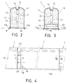
- Fig. 1 therefore illustrates the invention, implemented to provide protection and reinforcement in the lower part on both sides of a partition C. Conventionally, this consists of prefabricated panels juxtaposed 2.
- a continuous sole S prior to the installation of the panels, is provided over the entire length of the partition C, a continuous sole S, fixed firmly to the ground.
- the sole S has a substantial width relative to the thickness of the panels 2, and a height which, generally, is between 20 and 50 cm.
- the sole S consists of a series of identical modules 1 placed end to end, which essentially comprise a casing 10 open at its base and at its ends, advantageously made of stainless steel, and filled with a filler material forming a block 11, good thermal insulator and having appropriate mechanical properties. It can be a synthetic foam or a light concrete, based on polystyrene beads for example. Each module is fixed to the ground and to the module previously installed.
- the casing 10 defines at the top of the module 1 a longitudinal groove 12 intended to receive the base of the partition panels 2.
- the sole S therefore forms two sides on each side of the base, brought to be in different rooms where the temperature conditions can be very different. It is therefore necessary to eliminate as much as possible the thermal bridges between the two parts of the envelope 10 on each side of the groove 12.
- the envelope 10 is subdivided symmetrically into two pieces of sheet metal 13, each folded so as to present a vertical panel, an upper panel with double inclination, and an upper rim forming a part of the groove 12.
- the two sheet metal parts 13 are joined at the bottom of the groove 12 only by a few transverse isthmus 14 regularly spaced. Similarly, at their base, they are only joined at the ends of the module.
- the bottom connection of the parts 13 is provided by a flat transverse cross member 15.
- a median upright 16 connects the latter to the bottom of the groove 12, which upright carries two centering pins 17 arranged one above the other.
- a flat cross member 18 connects the two parts 13 similarly to the cross member 15.
- the cross member 18 is surmounted by an angle iron 19 which defines with it a space 20 open towards the outside.
- a median upright 21 connects the top of the angle 19 and the bottom of the groove 12, which has holes 22 for receiving the centering pins 17.
- the crosspiece 18 has two or more spaced holes, provided for receiving fixing screws to the ground.
- the concrete or foam block 11 comes flush with the outer face of the uprights 16 and 21, the outer edge of the cross member 15 and that of the angle iron 19. It completely fills the envelope 10 and constitutes the ground support of the module.
- the modules 1 must be fixed securely, as in many applications, in particular in the field of the food industry, and for hygienic reasons, a correct seal is necessary between the lower edges of the envelope 10 and the ground.
- the lower edges 13a, 13b of the casing 10, FIGS. 2, 3, protrude downward relative to the underside of the block 11.
- junction can be achieved by means of a seal, for example made of rubber, having two opposite grooves for receiving said edges.
- a seal for example made of rubber, having two opposite grooves for receiving said edges.
- the junction is produced by interlocking, a strip 23 forming the male part being welded to the internal face of the casing 10, projecting from its edge at one end, while at the other end, the female part or groove results from the superimposition by welding on the same internal face of the envelope of a first strip 24 set back from the edge, and of a second strip 25.
- a first module 1 is put in place. It is anchored in the ground at the level of the cross-member 18, the space 20 being provided to allow screwing. The module is therefore held by this end, and over its entire length by the lower edges of the envelope engaged in the ground.
- a second module 1 is placed after the first. It is connected to it by the centering pins 17, and by interlocking the adjacent edges of their envelopes, as illustrated in FIGS. 4 and 6. As can be seen in this last figure, the blocks 11 of filler material are then applied one against the other, of so there is no break in insulation.
- the second module is anchored to the ground at its free end, by screwing the crosspiece 18. This is done over the entire length of the partition to be built, after which the panels 2 are placed in the grooves 12. If water, electricity, compressed air, etc. are installed along the partition, cleaning passages for the pipes or sheaths in the block 11 and the casing 10 of the corresponding module before its installation.
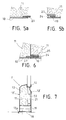
- a passage is shown in FIG. 12, consisting of a horizontal tube 26 embedded in the block 11 and opening at the end. The tube 26 can pass right through the module, or stop at the point of a tap in the casing 10.
- Fig. 14 schematically shows such a tap 27 in the upper panel of the wall 13 of a module, tap made with an external collar, at the end of a vertical hole in the block 11, for the passage of a conduit outlet 28.
- the collar is welded to the duct 28, which is connected below a sink or hand basin 29 fixed above the module, against the partition panel 2.
- modules can be provided, in the form of T, L and X. It is also possible to provide a range of modules shorter than modules 1, to directly make S soles whatever their length.
- the module 1 'shown in FIG. 7 is used to make a single sole, that is to say a sole forming reinforcement only on one side.
- This module is in all respects similar to the module 1 described above, comprising a block 11 of insulating filler material, an envelope 10 ′ in two parts 13, 13 ′ joined by points, with the same end means: low crosspieces, angle iron, uprights, centering pins.
- the part 13 ′ of the envelope is not shouldered, so that the groove 12, instead of being central, is offset on the outside of the module, its outer edge being perpendicular to the vertical wall of the envelope part 13 '.
- a single lower edge 13a of the casing 10 ′ is extended beyond the base of the block 11 which constitutes the bearing surface of the module, hence the need for a single groove in the floor for laying.
- the lower edge of the part 13 ′ can also be extended, if the sealing on the outside needs to be carried out with as much care as on the inside.
- Modules 3 and 3 'of Figs. 8 to 10 differ very little from modules 1 and 1 'in their structure. Like them, they comprise an envelope 10 or 10 ′ enclosing a block of insulating material 11 and defining an upper groove 12 for receiving partition elements 2.
- the block 11 does not completely fill the volume delimited by the envelope 10 or 10 ', but rather, there is reserved a free space 30 intended to receive a sealing concrete, which can be flowed through channels 31 passing through the block 11 from the bottom of the groove 12.
- a cross 18 with an angle 19 to define a space 20 are reproduced at the two ends of the modules 3 and 3 '.
- jacks 32 are mounted in place of screws for fixing to the ground, which is carried out by means of rods 34 engaged from the groove 12 in calibrated channels 33 passing through the block 11, and in holes in the ground aligned with the channels 33.
- the angle 19, and therefore the space 20 above the crosspiece 18 are eliminated, the screw of the jacks 32 being covered above the cross member 18, by means of a closed tube portion, for example.
- the modules 3 or 3 ' are first arranged on a first slab 35, the lower edge of the casings 10 or 10' being slightly raised. They are connected end to end by the adjacent end edges of their casings 10 or 10 ', the jacks 32 allowing adjustment. Then, drilling means are engaged in the channels 33 to provide in the slab for receiving the rods 34 which are then put in place. Note that an advantage of this method of fixing lies in the possibility of fixing the last module arriving against a pre-existing wall or partition.
- the sealing concrete is poured through the channels 31, which comes slightly beyond laterally under the lower edges of the modules. Finally, a finishing slab drowns these lower edges, symbolized by the thin line 36.
- the waterproofing concrete is poured at the desired height just before the installation of the modules 3 and 3 ', the channels 31 then serving as an overflow for the excess concrete.
- the modules can be placed on the slab carrying the floor covering, after a strip of it has been cut and removed.
- a connecting and sealing tape 37 is used, for example of the same material as the casing 10, which is housed by its two sides in two grooves formed in the end edges of the casings 10, by welding by strip points 24 and 25 as previously described.
- the T-module of FIG. 12, bearing the mark 4 is used for the T-junction of two partitions. As shown, its two branches 4b and 4c are single sole elements, and its foot 4a is a double sole element.
- the sheet metal parts 13 of its casing 10 have only one inclined section instead of two above the vertical section. Its slope is preferably at least greater than 30 ° relative to the horizontal, to ensure good flow of the washing water.
- the walls 13 and 13 ' have, at some distance above their lower edge, a small longitudinal recess 40.
- a set of wires is added by welding crossed 42, which is used for attaching a cement or finishing resin, with which one comes to form for example a rounding as shown schematically by the broken line in FIG. 13.
- the recess 41 can be provided to admit tiling.
- the sheet is normal to the vertical plane of the wall 13; and on the surface of the hollow 41, it is advantageously perforated to ensure better attachment of the fixing adhesive to the tiling.
- lateral tabs 43 added by welding to the bottom of its walls 13 and 13 ′ may be provided, which will be screwed or pointed, before being covered with cement or finishing resin, or by the tiling.
- the element 4b of the module 4 is shown incomplete, without its filling concrete 11, to reveal its internal structure.
- the filling concrete 11 is visible in the element 4a and in FIG. 13: it is stopped very close to the lower edge of the walls 13, the free space 30 reserved for the admission of sealing concrete having a very reduced uniform height, of the order of 1 to 2 cm.
- the realization of the waterproofing concrete according to the technique of pouring it at the desired height before the installation of the module is facilitated.
- variant modules according to the invention can combine the characteristics of two modules 1, 3 and 4, or 1 'and 3'.
- Fig. 15 shows a module 5 designed to make the end of a sole S adjacent to a door, of which the frame conventionally comprises uprights with a U-shaped section 50 to engage on the edge of the partition panels 2.
- the side wall 13 of the envelope of the module 5 is extended by a wall 51 which completely covers the end.
- the wall 50 forms an obtuse angle with it, advantageously of the order of 135 °, to allow correct release of the door leaves during opening.
- a section of U-shaped section 52 is placed vertically on the end, welded by the end of its wings to the wall 50.
- Said section 52 has a width equal to the thickness of the partition panels 2.
- the system of the invention is much simpler and faster to use than the other known systems.
- the disassembly of a sole poses no problem and, of course, the modules which constituted it are perfectly reusable.
- the system of the invention induces a significant cost reduction at the level of the panels 2, the surface of which is reduced by the height of the sole S.
Landscapes
- Engineering & Computer Science (AREA)
- Architecture (AREA)
- Civil Engineering (AREA)
- Structural Engineering (AREA)
- Building Environments (AREA)
Applications Claiming Priority (6)
| Application Number | Priority Date | Filing Date | Title |
|---|---|---|---|
| FR9303711A FR2704580A1 (fr) | 1993-03-26 | 1993-03-26 | Système de protection et de renfort des bas de cloisons dans des bâtiments industriels. |
| FR9303711 | 1993-03-26 | ||
| FR9309476 | 1993-07-27 | ||
| FR9309476A FR2704581A1 (fr) | 1993-03-26 | 1993-07-27 | Système de protection et de renfort des bas de cloisons dans des bâtiments industriels. |
| FR9313543 | 1993-11-08 | ||
| FR9313543A FR2704582B1 (fr) | 1993-03-26 | 1993-11-08 | Système de protection et de renfort des bas de cloisons dans des bâtiments industriels. |
Publications (1)
| Publication Number | Publication Date |
|---|---|
| EP0619405A1 true EP0619405A1 (de) | 1994-10-12 |
Family
ID=27252725
Family Applications (1)
| Application Number | Title | Priority Date | Filing Date |
|---|---|---|---|
| EP94460009A Ceased EP0619405A1 (de) | 1993-03-26 | 1994-03-23 | Schutz- oder Verstärkungssystem für Trennwandsockeln in Industriegebäuden |
Country Status (2)
| Country | Link |
|---|---|
| EP (1) | EP0619405A1 (de) |
| FR (1) | FR2704582B1 (de) |
Cited By (6)
| Publication number | Priority date | Publication date | Assignee | Title |
|---|---|---|---|---|
| FR2748509A1 (fr) * | 1996-05-09 | 1997-11-14 | Robaey Jacques | Procede de realisation d'une banquette de protection de la base d'un mur et moyens pour la mise en oeuvre du procede |
| AU720739B2 (en) * | 1996-01-04 | 2000-06-08 | Garry Reginald Johnstone | Cornices and mouldings |
| EP1045086A1 (de) * | 1999-04-16 | 2000-10-18 | Höganas Céramiques France | Verfahren zur Herstellung eines vorgefertigten Elementes auf Basis von Fliesen |
| FR2815063A1 (fr) * | 2000-10-11 | 2002-04-12 | A2Pc 2000 | Systeme de banquette de protection basse de murs ou cloisons |
| FR2847921A1 (fr) * | 2002-11-29 | 2004-06-04 | Chaudrolux | Dosseret de protection de la partie basse d'un mur |
| CN111485702A (zh) * | 2019-01-25 | 2020-08-04 | 河南天久装配式建筑有限公司 | 一种轻质混凝土内墙踢脚板结构及安装方法 |
Citations (8)
| Publication number | Priority date | Publication date | Assignee | Title |
|---|---|---|---|---|
| US2057204A (en) * | 1935-12-05 | 1936-10-13 | Knapp Brothers Mfg Company | Metallic baseboard construction |
| CH344205A (de) * | 1954-07-26 | 1960-01-31 | Braun Pebra Gmbh | Sockelleiste und Verwendung dieser Sockelleiste zur Herstellung eines Fussbodensockels |
| FR1308142A (fr) * | 1961-12-09 | 1962-11-03 | Mullca S A | Panneau joint extensible |
| CH385457A (fr) * | 1962-06-15 | 1964-12-15 | Ravanne Mirco | Dispositif d'amarrage d'un panneau sur un support et utilisation de ce dispositif |
| LU52284A1 (de) * | 1966-10-31 | 1967-01-03 | ||
| CH582286A5 (en) * | 1973-09-28 | 1976-11-30 | Ospelt Edwin | Concrete floor for wet process industries - has prefabricated concrete plates with thermal insulation on its underside |
| DE2927426A1 (de) * | 1979-07-06 | 1981-01-08 | Martin Gabler | Profilleiste |
| FR2640735A1 (fr) * | 1988-12-15 | 1990-06-22 | Wanner Isofi Isolation | Complexe isolant pour le revetement des parois d'une chambre froide et son procede de montage |
-
1993
- 1993-11-08 FR FR9313543A patent/FR2704582B1/fr not_active Expired - Fee Related
-
1994
- 1994-03-23 EP EP94460009A patent/EP0619405A1/de not_active Ceased
Patent Citations (8)
| Publication number | Priority date | Publication date | Assignee | Title |
|---|---|---|---|---|
| US2057204A (en) * | 1935-12-05 | 1936-10-13 | Knapp Brothers Mfg Company | Metallic baseboard construction |
| CH344205A (de) * | 1954-07-26 | 1960-01-31 | Braun Pebra Gmbh | Sockelleiste und Verwendung dieser Sockelleiste zur Herstellung eines Fussbodensockels |
| FR1308142A (fr) * | 1961-12-09 | 1962-11-03 | Mullca S A | Panneau joint extensible |
| CH385457A (fr) * | 1962-06-15 | 1964-12-15 | Ravanne Mirco | Dispositif d'amarrage d'un panneau sur un support et utilisation de ce dispositif |
| LU52284A1 (de) * | 1966-10-31 | 1967-01-03 | ||
| CH582286A5 (en) * | 1973-09-28 | 1976-11-30 | Ospelt Edwin | Concrete floor for wet process industries - has prefabricated concrete plates with thermal insulation on its underside |
| DE2927426A1 (de) * | 1979-07-06 | 1981-01-08 | Martin Gabler | Profilleiste |
| FR2640735A1 (fr) * | 1988-12-15 | 1990-06-22 | Wanner Isofi Isolation | Complexe isolant pour le revetement des parois d'une chambre froide et son procede de montage |
Cited By (8)
| Publication number | Priority date | Publication date | Assignee | Title |
|---|---|---|---|---|
| AU720739B2 (en) * | 1996-01-04 | 2000-06-08 | Garry Reginald Johnstone | Cornices and mouldings |
| FR2748509A1 (fr) * | 1996-05-09 | 1997-11-14 | Robaey Jacques | Procede de realisation d'une banquette de protection de la base d'un mur et moyens pour la mise en oeuvre du procede |
| EP1045086A1 (de) * | 1999-04-16 | 2000-10-18 | Höganas Céramiques France | Verfahren zur Herstellung eines vorgefertigten Elementes auf Basis von Fliesen |
| FR2792351A1 (fr) * | 1999-04-16 | 2000-10-20 | Hoganas Ceramiques France | Procede de construction d'un element prefabrique a base de carrelages |
| FR2815063A1 (fr) * | 2000-10-11 | 2002-04-12 | A2Pc 2000 | Systeme de banquette de protection basse de murs ou cloisons |
| EP1197612A1 (de) * | 2000-10-11 | 2002-04-17 | A2PC 2000 (Sarl) | Schutzwandsockelleiste |
| FR2847921A1 (fr) * | 2002-11-29 | 2004-06-04 | Chaudrolux | Dosseret de protection de la partie basse d'un mur |
| CN111485702A (zh) * | 2019-01-25 | 2020-08-04 | 河南天久装配式建筑有限公司 | 一种轻质混凝土内墙踢脚板结构及安装方法 |
Also Published As
| Publication number | Publication date |
|---|---|
| FR2704582B1 (fr) | 1997-04-11 |
| FR2704582A1 (fr) | 1994-11-04 |
Similar Documents
| Publication | Publication Date | Title |
|---|---|---|
| FR2781036A1 (fr) | Cuve etanche et thermiquement isolante a barriere isolante simplifiee, integree dans une structure porteuse de navire | |
| EP0581664A1 (de) | Panel zum wärmedäuerenden Bekleiden von Gebäudewänden | |
| EP1133605B1 (de) | Verlorene schalung und die verwendung als füllkörper und gewölbe | |
| EP1434920A1 (de) | Wärmesperrvorrichtung für betonboden und damit ausgestatteter boden | |
| FR2633019A1 (fr) | Procede et dispositif de jonction etanche de panneaux exposes au ruissellement | |
| EP0619405A1 (de) | Schutz- oder Verstärkungssystem für Trennwandsockeln in Industriegebäuden | |
| FR2754285A1 (fr) | Element de coffrage isolant pour mur en beton | |
| EP0141453B1 (de) | Vorgefertigte Wandverkleidungsplatte, Herstellungsverfahren und Verwendung | |
| FR3118979A1 (fr) | Panneau de construction et procédé de fabrication d’un mur au moyen d’un tel panneau | |
| EP1916336A1 (de) | Insulation and sealing device for a rail, in particular for a tramway, mounted on sleepers | |
| FR2476719A1 (fr) | Construction formee d'elements prefabriques disposes en rangees superposees dans lesquelles les elements sont disposes tete-beche | |
| FR2704581A1 (fr) | Système de protection et de renfort des bas de cloisons dans des bâtiments industriels. | |
| EP3070220B1 (de) | Verfahren zur behandlung von wärmebrücken | |
| EP1004717B1 (de) | Hohlbausteinsatz | |
| FR2704580A1 (fr) | Système de protection et de renfort des bas de cloisons dans des bâtiments industriels. | |
| EP0784128B1 (de) | Verfahren zur Herstellung eines Paneels mit tragender Holzkonstruktion, durch das Verfahren hergestelltes Paneel, und mindestens ein derartiges Paneel enthaltendes Bauwerk | |
| EP3070222B1 (de) | Fertigbauelement und herstellungsverfahren eines solchen fertigbauelements | |
| FR2642789A1 (fr) | Coffrage de volet roulant pour installation sur la partie superieure d'un cadre de dormant | |
| FR2556041A1 (fr) | Perfectionnement aux vitrages supportes, sans mastic, par des profiles | |
| FR2812323A1 (fr) | Piscine du type composee d'elements prefabriques en beton arme | |
| EP2412889B1 (de) | Halterungsvorrichtung für eine Überdachung und Herstellungsverfahren einer solchen Halterungsvorrichtung | |
| FR2795110A1 (fr) | Coffrage isolant pour la realisation d'un mur en beton | |
| BE506650A (de) | ||
| FR2735803A1 (fr) | Bloc de construction isole autocoffrant | |
| FR2578278A1 (fr) | Procede de construction de batiments par assemblage mecanique d'elements de construction prefabriques et elements correspondants |
Legal Events
| Date | Code | Title | Description |
|---|---|---|---|
| PUAI | Public reference made under article 153(3) epc to a published international application that has entered the european phase |
Free format text: ORIGINAL CODE: 0009012 |
|
| AK | Designated contracting states |
Kind code of ref document: A1 Designated state(s): BE CH DE ES GB IT LI NL PT |
|
| 17P | Request for examination filed |
Effective date: 19941121 |
|
| 17Q | First examination report despatched |
Effective date: 19951106 |
|
| GRAG | Despatch of communication of intention to grant |
Free format text: ORIGINAL CODE: EPIDOS AGRA |
|
| STAA | Information on the status of an ep patent application or granted ep patent |
Free format text: STATUS: THE APPLICATION HAS BEEN REFUSED |
|
| 18R | Application refused |
Effective date: 19981221 |