EP0619441A1 - Vorrichtung zur Dämpfung von Vibrationen und Verfahren zu dessen Herstellung - Google Patents
Vorrichtung zur Dämpfung von Vibrationen und Verfahren zu dessen Herstellung Download PDFInfo
- Publication number
- EP0619441A1 EP0619441A1 EP94400710A EP94400710A EP0619441A1 EP 0619441 A1 EP0619441 A1 EP 0619441A1 EP 94400710 A EP94400710 A EP 94400710A EP 94400710 A EP94400710 A EP 94400710A EP 0619441 A1 EP0619441 A1 EP 0619441A1
- Authority
- EP
- European Patent Office
- Prior art keywords
- visco
- rubber
- vibration
- vibration damping
- vibration isolation
- Prior art date
- Legal status (The legal status is an assumption and is not a legal conclusion. Google has not performed a legal analysis and makes no representation as to the accuracy of the status listed.)
- Granted
Links
Images









Classifications
-
- B—PERFORMING OPERATIONS; TRANSPORTING
- B32—LAYERED PRODUCTS
- B32B—LAYERED PRODUCTS, i.e. PRODUCTS BUILT-UP OF STRATA OF FLAT OR NON-FLAT, e.g. CELLULAR OR HONEYCOMB, FORM
- B32B15/00—Layered products comprising a layer of metal
- B32B15/04—Layered products comprising a layer of metal comprising metal as the main or only constituent of a layer, which is next to another layer of the same or of a different material
- B32B15/06—Layered products comprising a layer of metal comprising metal as the main or only constituent of a layer, which is next to another layer of the same or of a different material of natural rubber or synthetic rubber
-
- B—PERFORMING OPERATIONS; TRANSPORTING
- B32—LAYERED PRODUCTS
- B32B—LAYERED PRODUCTS, i.e. PRODUCTS BUILT-UP OF STRATA OF FLAT OR NON-FLAT, e.g. CELLULAR OR HONEYCOMB, FORM
- B32B7/00—Layered products characterised by the relation between layers; Layered products characterised by the relative orientation of features between layers, or by the relative values of a measurable parameter between layers, i.e. products comprising layers having different physical, chemical or physicochemical properties; Layered products characterised by the interconnection of layers
- B32B7/04—Interconnection of layers
- B32B7/08—Interconnection of layers by mechanical means
-
- B—PERFORMING OPERATIONS; TRANSPORTING
- B32—LAYERED PRODUCTS
- B32B—LAYERED PRODUCTS, i.e. PRODUCTS BUILT-UP OF STRATA OF FLAT OR NON-FLAT, e.g. CELLULAR OR HONEYCOMB, FORM
- B32B25/00—Layered products comprising a layer of natural or synthetic rubber
- B32B25/04—Layered products comprising a layer of natural or synthetic rubber comprising rubber as the main or only constituent of a layer, which is next to another layer of the same or of a different material
- B32B25/042—Layered products comprising a layer of natural or synthetic rubber comprising rubber as the main or only constituent of a layer, which is next to another layer of the same or of a different material of natural rubber or synthetic rubber
-
- B—PERFORMING OPERATIONS; TRANSPORTING
- B32—LAYERED PRODUCTS
- B32B—LAYERED PRODUCTS, i.e. PRODUCTS BUILT-UP OF STRATA OF FLAT OR NON-FLAT, e.g. CELLULAR OR HONEYCOMB, FORM
- B32B7/00—Layered products characterised by the relation between layers; Layered products characterised by the relative orientation of features between layers, or by the relative values of a measurable parameter between layers, i.e. products comprising layers having different physical, chemical or physicochemical properties; Layered products characterised by the interconnection of layers
- B32B7/02—Physical, chemical or physicochemical properties
- B32B7/022—Mechanical properties
-
- B—PERFORMING OPERATIONS; TRANSPORTING
- B32—LAYERED PRODUCTS
- B32B—LAYERED PRODUCTS, i.e. PRODUCTS BUILT-UP OF STRATA OF FLAT OR NON-FLAT, e.g. CELLULAR OR HONEYCOMB, FORM
- B32B7/00—Layered products characterised by the relation between layers; Layered products characterised by the relative orientation of features between layers, or by the relative values of a measurable parameter between layers, i.e. products comprising layers having different physical, chemical or physicochemical properties; Layered products characterised by the interconnection of layers
- B32B7/04—Interconnection of layers
- B32B7/12—Interconnection of layers using interposed adhesives or interposed materials with bonding properties
-
- F—MECHANICAL ENGINEERING; LIGHTING; HEATING; WEAPONS; BLASTING
- F16—ENGINEERING ELEMENTS AND UNITS; GENERAL MEASURES FOR PRODUCING AND MAINTAINING EFFECTIVE FUNCTIONING OF MACHINES OR INSTALLATIONS; THERMAL INSULATION IN GENERAL
- F16B—DEVICES FOR FASTENING OR SECURING CONSTRUCTIONAL ELEMENTS OR MACHINE PARTS TOGETHER, e.g. NAILS, BOLTS, CIRCLIPS, CLAMPS, CLIPS OR WEDGES; JOINTS OR JOINTING
- F16B43/00—Washers or equivalent devices; Other devices for supporting bolt-heads or nuts
-
- F—MECHANICAL ENGINEERING; LIGHTING; HEATING; WEAPONS; BLASTING
- F16—ENGINEERING ELEMENTS AND UNITS; GENERAL MEASURES FOR PRODUCING AND MAINTAINING EFFECTIVE FUNCTIONING OF MACHINES OR INSTALLATIONS; THERMAL INSULATION IN GENERAL
- F16B—DEVICES FOR FASTENING OR SECURING CONSTRUCTIONAL ELEMENTS OR MACHINE PARTS TOGETHER, e.g. NAILS, BOLTS, CIRCLIPS, CLAMPS, CLIPS OR WEDGES; JOINTS OR JOINTING
- F16B5/00—Joining sheets or plates, e.g. panels, to one another or to strips or bars parallel to them
- F16B5/04—Joining sheets or plates, e.g. panels, to one another or to strips or bars parallel to them by means of riveting
-
- F—MECHANICAL ENGINEERING; LIGHTING; HEATING; WEAPONS; BLASTING
- F16—ENGINEERING ELEMENTS AND UNITS; GENERAL MEASURES FOR PRODUCING AND MAINTAINING EFFECTIVE FUNCTIONING OF MACHINES OR INSTALLATIONS; THERMAL INSULATION IN GENERAL
- F16F—SPRINGS; SHOCK-ABSORBERS; MEANS FOR DAMPING VIBRATION
- F16F1/00—Springs
- F16F1/36—Springs made of rubber or other material having high internal friction, e.g. thermoplastic elastomers
- F16F1/40—Springs made of rubber or other material having high internal friction, e.g. thermoplastic elastomers consisting of a stack of similar elements separated by non-elastic intermediate layers
- F16F1/403—Springs made of rubber or other material having high internal friction, e.g. thermoplastic elastomers consisting of a stack of similar elements separated by non-elastic intermediate layers characterised by the shape of the non-elastic interengaging parts between the elements
-
- B—PERFORMING OPERATIONS; TRANSPORTING
- B32—LAYERED PRODUCTS
- B32B—LAYERED PRODUCTS, i.e. PRODUCTS BUILT-UP OF STRATA OF FLAT OR NON-FLAT, e.g. CELLULAR OR HONEYCOMB, FORM
- B32B2307/00—Properties of the layers or laminate
- B32B2307/50—Properties of the layers or laminate having particular mechanical properties
- B32B2307/56—Damping, energy absorption
-
- B—PERFORMING OPERATIONS; TRANSPORTING
- B32—LAYERED PRODUCTS
- B32B—LAYERED PRODUCTS, i.e. PRODUCTS BUILT-UP OF STRATA OF FLAT OR NON-FLAT, e.g. CELLULAR OR HONEYCOMB, FORM
- B32B2309/00—Parameters for the laminating or treatment process; Apparatus details
- B32B2309/08—Dimensions, e.g. volume
- B32B2309/10—Dimensions, e.g. volume linear, e.g. length, distance, width
- B32B2309/105—Thickness
-
- F—MECHANICAL ENGINEERING; LIGHTING; HEATING; WEAPONS; BLASTING
- F16—ENGINEERING ELEMENTS AND UNITS; GENERAL MEASURES FOR PRODUCING AND MAINTAINING EFFECTIVE FUNCTIONING OF MACHINES OR INSTALLATIONS; THERMAL INSULATION IN GENERAL
- F16B—DEVICES FOR FASTENING OR SECURING CONSTRUCTIONAL ELEMENTS OR MACHINE PARTS TOGETHER, e.g. NAILS, BOLTS, CIRCLIPS, CLAMPS, CLIPS OR WEDGES; JOINTS OR JOINTING
- F16B5/00—Joining sheets or plates, e.g. panels, to one another or to strips or bars parallel to them
- F16B5/02—Joining sheets or plates, e.g. panels, to one another or to strips or bars parallel to them by means of fastening members using screw-thread
-
- Y—GENERAL TAGGING OF NEW TECHNOLOGICAL DEVELOPMENTS; GENERAL TAGGING OF CROSS-SECTIONAL TECHNOLOGIES SPANNING OVER SEVERAL SECTIONS OF THE IPC; TECHNICAL SUBJECTS COVERED BY FORMER USPC CROSS-REFERENCE ART COLLECTIONS [XRACs] AND DIGESTS
- Y10—TECHNICAL SUBJECTS COVERED BY FORMER USPC
- Y10S—TECHNICAL SUBJECTS COVERED BY FORMER USPC CROSS-REFERENCE ART COLLECTIONS [XRACs] AND DIGESTS
- Y10S411/00—Expanded, threaded, driven, headed, tool-deformed, or locked-threaded fastener
- Y10S411/90—Fastener or fastener element composed of plural different materials
Definitions
- the present invention relates to a vibration damping body suitable for a washer used for a clamping bolt in a machine, an apparatus, etc. or a body constructed by press such as an oil pan, a ventilation buffle plate, etc. in an automobile and a method for fabricating same.
- Noise is produced generally in such a manner that various sorts of vibrations generated by movement in different kinds of machines and apparatuses originating it, are transferred to other members, are resonated therewith, and radiated them as noise. Vibration isolation materials are used for preventing this transfer of vibrations to other members (vibration isolation).
- vibration isolation materials described above are roughly classified into a group of coil springs and another group of vibration isolation rubbers.
- Coil springs are used for lowering vibration level by varying a natural frequency to avoid resonance with vibration having an object frequency, while vibration isolation rubbers attenuate vibration principally by internal friction within a visco-elastic body made of rubber to isolate vibration as the result.
- vibration isolation rubbers are used for vibration isolation in a wide frequency range.
- a vibration isolation washer formed in a washer shape is used often in a portion bound by means of a bolt for the purpose of preventing that engine vibration in automobile, etc. is transferred to another member such as a head cover, an oil pan, etc. through a clamping bolt, etc. and radiated as noise.
- Usual vibration isolation washers are mainly made of rubber-molded bodies and further in addition to them, various constructions such as a washer made of rubber alone, a washer in which metal plates are stuck by vulcanization adhesion on the upper and lower surfaces of a simple rubber body, etc. are used, depending on the field of utilization.
- a vibration isolation washer in which a metal support is stuck to a surface of a rubber piece by vulcanization adhesion, is widely utilized.
- This type of vibration isolation rubbers consists in that not only the sort and the shape thereof can be arbitrarily chosen, depending on the field of utilization, but also the vibration isolation capability can be freely designed.
- this type of vibration washers have following drawbacks.
- Capability of a rubber-molded vibration isolation washer with metal support depends significantly on properties which rubber has (hardness, tensile strength, compression and recovery, compression set, etc.) and further on heat resistant properties thereof as well as other resistances to environments, in order that it can exhibit stably vibration isolation and other required characteristics. Generally it is believed that these variations are unavoidable.
- a structure in which a plurality of raw material sheets, in each of which a rubber visco-elastic layer is stuck to a metal plate formed in a dish shape, are laminated on each other, in order to improve the vibration isolation effect and a long term creep resistant property.
- this conceived structure cannot exhibit the vibration isolation effect owing to prolongation and complication of the vibration transmission path stated later according to the present invention, but also since different laminated sheets move freely at fastening, unnecessary friction is produced at interfaces of rubber/rubber and rubber/metal, which gives rise to an inconvenience that the surface of the rubber is worn away or peeled.
- JP-A-Sho 60-81511 a structure is proposed, in which rubber layers having the vibration damping effect and two or three metal plates (or vibration damping alloy plates) are laminated and adhered alternately.
- rubber layers having the vibration damping effect and two or three metal plates (or vibration damping alloy plates) are laminated and adhered alternately.
- a vibration damping member composed by putting a macromolecular visco-elastic layer made of rubber, resin, etc. between two metal plates in a sandwich shape is used as a pressed construction itself, which is formed by press, or a macromolecular visco-elastic layer made of rubber, synthetic resin, etc. is disposed on either one of the inner or the outer surface of the construction to obtain a vibration damping property.
- the former has an advantage that the sealing and the vibration damping function can be utilized together by using the sealing function of the macromolecular visco-elastic layer on the surface, while the latter requires a separate sealing member such as a gasket, etc.
- vibration isolation washer it is absolutely necessary for the vibration isolation washer described above for the field of utilization where reliability is considered to be important as parts for an engine in an automobile to have not only a high vibration isolating property but also various characteristics such as resistance against creep, initial clamping properties (easiness to fasten, torque transmissibility, torsion strength), resistance against environment, etc. together and appearance of a vibration isolation washer fulfilling satisfactorily these conditions is desired.
- a ventilation damping structure in which a macromolecular visco-elastic layer is put between two metal plates (constrained damping material), has a disadvantage that cost is high in the aspect of fabrication, although it has a high loss factor. Further, in the case where the constrained vibration damping structure should have a sealing property, it requires a separate gasket.
- a first object of the present invention is to provide a vibration damping construction, which satisfies simultaneously all of the vibration isolation property under a high load environment, the creep resistant property (compression crush resistant property, long term creep resistant property), the initial clamping properties (easiness to clamp, torque transmissibility, torsion strength), and environment resistant property (oil, salt water), in the case where it is applied to a vibration isolation washer, and a method for fabricating same.
- the creep resistant property compression crush resistant property, long term creep resistant property
- the initial clamping properties easiness to clamp, torque transmissibility, torsion strength
- environment resistant property oil, salt water
- a second object of the present invention is to provide a vibration damping construction, capable of giving a unconstrained damping material a constrained vibration damping function, in the case where it is applied to a pressed construction such as an oil pan, a ventilation buffle plate for an automobile, and in addition which can exhibit a vibration damping effect in a wide temperature range, which had not be able to be obtained with a prior art constrained damping steel plate.
- a vibration damping construction according to the present invention is constructed by using a combination of a rigid body with a raw material including a macromolecular visco-elastic layer or two such layers formed on one surface or two surfaces of the rigid body or a combination of such raw materials, laminating members comprising such combinations, and forming them in one body by spot connection.
- a vibration damping body for a vibrating isolation washer is constructed according to the present invention
- raw materials in each of which a rubber visco-elastic layer or such layers is or are disposed on one or two surfaces of a metal plate, are used, which raw materials are laminated on each other, so that rubber visco-elastic layers are opposite to each other, and adhered to each other to form a laminated body; laminated bodies thus obtained or laminated bodies and raw materials are laminated on each other to form a laminated layer construction and caulked mechanically in one body by spot connection by means of a plurality of pawls cut and raised in the thickness direction thereof.
- a macromolecular visco-elastic layer is formed on a base plate, which is a rigid body, by adhesion, and a plate-shaped member, which is a rigid body, is laminated on the surface of this macromolecular visco-elastic layer, which plate-shaped member is bound with the base plate by spot connection.
- the vibration damping body is applied to a vibration damping washer, in spite of the fact that it is thinner than a prior art vibration damping rubber and it has a high rigidity, it is possible to obtain not only a vibration damping and sound proof property higher than that of the prior art vibration damping rubber but also a good and stable clamping property. Further it is possible to obtain a small exposed area of the macromolecular visco-elastic layer made of rubber, etc. and thus it can exhibit an excellent environment resistant property.
- the vibration damping body described above is applied to a pressed construction such as an oil pan, a ventilation buffle plate for an automobile, the vibration damping action thereof can be exhibited in a wide temperature range.
- a1 and b1 indicate basic components of a vibration isolation washer and reference numeral 1 is a metal plate; 2 is a rubber visco-elastic layer; and 3 is an adhesive layer.
- the basic component a1 is constructed by adhering raw materials, each of which includes rubber visco-elastic layers 2 disposed on two surfaces of the metal plate 1, to each other through the adhesive layer 3 so that rubber visco-elastic layers are opposite to each other so as to have a structure of a constrained vibration damping plate itself.
- the basic component b1 includes a metal plate 1, on one surface of which the rubber visco-elastic layer 2 is formed so as to have a structure of an unconstrained damping material itself.
- the basic components b1, b1 are laminated on the basic component a1 so that rubber visco-elastic layers are opposite to each other.
- An aluminium plate, an iron plate, a steel plate, a stainless steel plate, etc. may be cited for the metal plate constituting the raw material described above and a plate about 0.1 to 1.0mm thick is used therefor.
- acrylonitrile butadiene rubber NBR
- styrene butadiene rubber SBR
- natural rubber NR
- butyl rubber IIR
- butadiene rubber BR
- isoprene rubber IR
- chloroprene rubber CR
- ACM acryl rubber
- the raw material described above can be obtained easily by coating one surface or two surfaces of the metal plate with liquid rubber material described above and by vulcanizing the liquid rubber material to form the rubber visco-elastic layer.
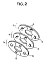
- a plurality of rectangular cut and raised pawls 4 are disposed in the circumferential direction on the basic component b1 in the upper layer and the basic component a1 in the middle layer among the basic components b1 - a1 - b1 described above.
- rectangular cut-off windows 5 having the same shape as the pawls stated above are formed in the basic component b1 in the lower layer.
- the pawls 4 formed on the basic component a1 in the middle layer are engaged with the cut-off windows 5 formed in the basic component b1 in the lower layer and the pawls 4 formed on the basic component b1 in the upper layer is engaged with cut-off windows formed due to the cut and raised pawls 4 on the basic component a1 in the middle layer by laminating the basic components b1 - a1 - b1 on each other and pressing them in the thickness direction. All the basic components b1 - a1- b1 laminated on each other are bound by spot connection due to engaging action of the pawls described above.
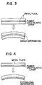
- the basic component a1 has the constrained damping structure indicated in Fig. 3.
- the vibration damping power is exhibited by "shear deformation" of the rubber visco-elastic material due to bending vibration.
- the basic component b1 has the unconstrained damping structure indicated in Fig. 4 and in this structure the vibration damping power is exhibited by "extensional deformation" of the rubber visco-elastic material due to bending vibration
- the constrained type and the unconstrained type are compared, they are different in that the effect is exhibited by the thin rubber visco-elastic layers in the former, while a thickness three or four times as great as that of the metal plate is required for the unconstrained type, a higher vibration damping property can be obtained with increasing number of lamination of the basic components described above, i.e. with increasing total thickness of rubber visco-elastic layers laminated alternately with metal plates.
- the basic components b1, a1 and b1 are not adhered to each other, but bound by spot connection and the surfaces other than the spot connections are only contacted so that extremely small "Coulomb friction" is produced at interfaces between different basic components when vibration is generated. In this way vibration energy is transformed into friction heat, so that vibration absorbing effect can be obtained, too.
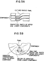
- vibration damping washer constructed as described above, as indicated in Figs. 5A and 5B, e.g. vibration flowing into the basic component, which is on the lower side, is transmitted to the basic component, which is on the upper side, through contacting parts (hatched parts in Fig. 5A) on the side surfaces of the cut and raised pawls, which are formed on the upper side member, and thus vibration damping effect can be obtained by prolongation and complication of the vibration transmission path.
- Figs. 6A, 6B, 6C, 6D, 6E and 6F show various sorts of examples of the direction and the position of the cutting, in the case where the cut and raised pawls 4 for caulking are formed on the basic components, in plan views, while Figs. 7A, 7B, 7C and 7D show them in cross-sectional views, Figs. 7A, 7B and 7C indicating examples of the construction, where they are caulked on one side, Fig. 7D indicating an example of the construction, where it is caulked on the two sides.
- Fig. 8 shows preferable basic components.
- b1 is a raw material, in which a rubber visco-elastic layer 2 is formed on one surface of a metal plate 1 and b2 is a raw material, in which two rubber visco-elastic layers 2 are formed on the two surfaces of a metal plate 1.
- a1 is a multi-layered body, in which raw materials b2 described above are stuck to each other through an adhesive layer 3;
- a2 is a multi-layered body, in which raw materials b1 described above are stuck to each other through an adhesive layer 3;
- a3 is a multi-layered body, in which raw materials b1 and b2 are stuck to each other through an adhesive layer 3.
- the contacting interface at combining these basic components is composed of rubber/rubber or rubber/metal in principle.
- Figs. 9 to 13 show how vibration isolation washers are constructed by combining the basic components indicated in Fig. 8. However spot connecting means are omitted in the figures.
- a vibration isolation washer according to the present embodiment has a structure, in which four basic cqmponents a1 are laminated on each other and bound in one body by using cut and raised pawls described previously, as indicated in Fig. 9.
- Method for Fabricating the Basic Component :
- one surface or two surfaces of a metal plate, which has been subjected to surface processing is/are coated and made react with primer efficient for adhesion to rubber. Thereafter it/they is/are coated thin and uniformly with rubber dissolved in a solvent and subjected to a vulcanization process at a predetermined temperature to obtain the raw material (unconstrained damping material).
- This structure is useful, in the case where it is sealed against liquid (oil, etc.) flowing along the bolt, by disposing rubber layers for the outermost layers.
- Rectangular portions are cut away at the positions for caulking by means of pawls only from the lowest basic component among those laminated on each other.
- three sides of the rectangles at the positions for caulking by means of pawls are cut, leaving the remaining one side not cut, and the rectangles are raised to be used for the caulking.
- the number of caulked positions is 4.
- the arrangement thereof in a plan view is indicated in Fig. 6A and the cross-sectional structure is shown in Fig. 7A.
- a vibration isolation washer according to the present embodiment has such structure, that basic components b1, a1, a1 and b1 are laminated on each other and bound in one body by using cut and raised pawls described previously, as indicated in Fig. 10.
- the present embodiment differs from EMBODIMENT (1) in that the aluminium plates 1 in the outermost basic components b1 are 0.6mm thick. It is in view of intending to resist crush due to concentrated load at the head portion of the bolt that aluminium plates thicker than the others are used for the outermost surfaces.
- a vibration isolation washer according to the present embodiment has such structure, that the number of intermediate basic components is reduced by 1 with respect to that described in EMBODIMENT (2), as indicated in Fig. 11, and there are no other modifications.
- a vibration isolation washer according to the present example for comparison, four basic components a1 described in EMBODIMENT (1) are used, as indicated in Fig. 12, which are assembled by means of a bolt, etc. in a separate state without using any means for "caulking by means of pawls" and “adhesion", to be tested. For this reason attention is paid particularly so that no displacement, etc. is produced between different layers.
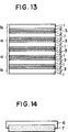
- a vibration isolation washer according to the present example for comparison is constructed by adhering the whole surfaces of the basic components b1, a1, a1 and b1 used in EMBODIMENT (2) in one body, as indicated in Fig. 13. For this reason the overall thickness thereof is greater than that described in EMBODIMENT (2) by the thickness of the adhesive films newly used.
- a polyamide type adhesive film 3 (0.03mm thick) is put between every adjacent two basic components and they are adhered to each other at a temperature lower than their melting point by means of a hot press.
- a vibration isolation washer according to the present example for comparison is constructed by molding a NBR type rubber piece 7 3.5mm thick and sticking it with a support 1mm thick made of iron by vulcanization and adhesion, as indicated in Fig. 14. This is one of the vibration isolation washers most widely utilized heretofore.
- This thickness of the rubber piece is overwhelmingly great among the embodiments and examples for comparison described above and 1.8 times as great as that used in EMBODIMENT (1).
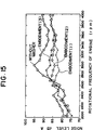
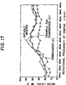
- Sound pressure levels corresponding to different rotational frequencies of engine are measured by using a bench test apparatus for an engine of an automobile.
- Vibration isolation washers according to the embodiments and the examples for comparison are used for all the parts clamped by bolts binding an engine head cover to a cylinder head to be tested.
- the bodies to be tested are clamped to the head cover with a constant torque. Thereafter the engine is started and the rotational frequency is increased with a constant interval.
- Equivalent sound pressure level is measured for every rotational frequency at a position 15cm high over the central portion of the head cover by means of a sound pressure meter.
- the sound pressure level is compared while paying attention specifically to a resonance peak sound pressure level found at 2400 - 3400 rpm and further for characteristic rotational frequency at need, when vibration isolation washers are used and not used.
- the resonance sound pressure level is 95dB(A), in the case where no vibration isolation washers are used.
- a higher sound insulating effect can be expected for vibration isolation washers giving lower sound pressure levels.
- Torque transmissibilities are indicated in the graph in Fig. 19.
- Fig. 20 shows an enlarged graph of a part thereof.
- a relation between the rotational angle of a torque wrench and the attainable torque is measured, when bodies to be tested are clamped to an aluminium plate, in which female screws are formed.
- torque transmissibility is evaluated by using a rotational angle necessary for clamping torque to arrive at 100 kgf-cm.
- the torque transmissibility is higher and more stable clamping is possible, when this value is smaller.
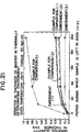
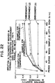
- Compression set which is an index for the long term creep property, is indicated in the graph in Fig. 21.
- Fig. 22 is an enlarged graph of a part of Fig. 21.
- Bodies to be tested are clamped to an aluminium plate, in which female screws are formed, by a bolt with a constant toque. Variations in the thickness of the bodies to be tested after having left them in long periods of time under thermally deteriorating environment are measured and the aspect thereof is observed.
- thermally deteriorating environment is 130°C x 200 hours and bodies to be tested are clamped with a torque of 50 kgf-cm.
- Looseness of the bolt is smaller and a higher remaining torque can be kept, when variations in the thickness are smaller.
- the sound pressure level at the resonance peak is about 85dB(A) and sound pressure levels for other rotational frequencies are also kept generally low.
- the attenuation level of the sound level is really as great as 10dB, compared with that obtained in the case where no washers are used.
- the highest sound insulating effect can be obtained among the embodiments and the examples for comparison.
- Variations in the thickness are about 0.3mm. No protrusions of the rubber visco-elastic layers are found and the aspect after the test is good.
- the sound pressure level at the resonance peak is about 86dB(A). Although it is somewhat higher than that obtained for EMBODIMENT (1), the attenuation level of the sound pressure is as higher as 9dB with respect to that obtained without washer.
- Variations in the thickness are about 0.2mm. No protrusions of the rubber visco-elastic layers, etc. are found and the aspect after the test is good.
- the sound pressure level at the resonance peak is about 88dB(A). Although it is somewhat higher than that obtained for EMBODIMENT (2), decrease in the sound pressure level is as high as 7dB with respect to that obtained without washer and a high sound insulating effect is exhibited. Torque Transmissibility:
- Variations in the thickness are about 01.mm. No protrusions of the rubber visco-elastic layers, etc. are found and the aspect after the test is good.
- the sound pressure level at the resonance peak is about 85dB(A). There are no differences in the sound pressure level from EMBODIMENT (1). (However an upward shift of the peak rotational frequency is found.)
- the sound pressure level at the resonance peak is about 92dB(A), which is higher by 6dB than that obtained in EMBODIMENT (2). On the other hand, it is decreased by about 3dB with respect to that obtained without washer.
- Variations in the thickness are 0.2mm. No protrusions of the rubber visco-elastic layers, etc. are found and the aspect after the test is good.
- the sound pressure level at the resonance peak is about 90dB(A), which is somewhat higher than those obtained in EMBODIMENTS (1), (2) and (3). Although the rubber visco-elastic layers is thickest in embodiments and examples for comparison, decrease in the sound pressure level is only 5dB with respect to that obtained without washer. Torque Transmissibility:
- Variations in the thickness are about 0.9 to 1.0mm, which are three to ten times as great as those obtained in embodiments. Further protrusions and breaks of the rubber visco-elastic layers are found after the test.
- the vibration isolation washer according to the present invention is constructed by using raw materials, in each of which a rubber visco-elastic layer or such layers is or are disposed on one or two surfaces of a metal plate, which raw materials are laminated on each other, so that rubber visco-elastic layers are opposite to each other, and adhered to each other to form a laminated body; and by laminating laminated bodies thus obtained or laminated bodies and raw materials on each other to form a laminated layer construction and caulking them mechanically in one body by spot connection by means of a plurality of pawls cut and raised in the thickness direction thereof, it is possible to realize not only a vibration attenuation effect by rubber visco-elastic layers but also an excellent "torque transmissibility" and "long term creep resistant property” owing to the fact that the total quantity of rubber visco-elastic layers in the overall thickness is necessarily reduced and the amount of compression in every rubber visco-elastic layer is remarkably suppressed.
- each of rubber visco-elastic layers laminated on each other cannot be defined generally, depending on the material as far as the embodiments described above concern, satisfactory results can be obtained, if it is comprised between 0.03 and 0.50mm. However, ideally, if it is comprised between 0.03 and 0.20mm, further satisfactory results can be obtained.
- a higher vibration isolation property (sound insulation property) can be obtained with increasing number of layers laminated on each other in the multi-layered body, each of which constitutes a basic component, that is, with increasing total thickness of the rubber visco-elastic layers laminated alternately with metal plates. This corresponds to a mechanism wherein vibration energy is transformed into thermal energy by internal friction in the rubber visco-elastic layers and as the result vibration isolation is obtained.
- a second mechanism is the "vibration energy absorbing effect by Coulomb friction", which is one of the new vibration isolation mechanisms according to the present invention.
- a third mechanism is a "vibration attenuation effect by prolongation and complication of the vibration transmission path, which is another vibration isolation mechanism according to the present invention.
- the first mechanism for the purpose of securing the overall thickness of the rubber visco-elastic layers giving a better vibration isolation property than that obtained by a prior art vibration isolation washer, it is sufficient to increase the thickness of each of the rubber layers and/or the number of layers laminated on each other.
- the thickness of the rubber layers which can exhibit a high vibration isolation, is fairly great. Further since it is a composite body with metal plates, overall thickness is very great and it cannot be said to be practical.
- the "mechanical spot connecting means by means of pawls" is efficient not only for facilitating production of extremely small “Coulomb friction", which is the second mechanism, but also since it makes efficient use of mechanical strength of a metal material, it has effects of preventing peeling and breaking taking place together with torsion of rubber at initial clamping (torsion strength) and making it possible to transfer precisely torque. Therefore it can be said that it is inevitable for use as a vibration isolation washer, to which twisting torque is loaded necessarily.
- the "mechanical spot connecting means by means of pawls" is fabricated by processing basic components and requires no other "auxiliary materials".
- this gives rise to many advantages that it is possible to design the size of the washer so that the area necessary for vibration isolation is as large as possible, that it is not necessary to take into account chemical and physical influences of the "auxiliary materials" on the mounting portion, etc.
- Fig. 23 is a perspective view of a ventilation buffle plate and Figs. 24A to 24H show various sorts of constructions of the spot connections.
- M is a pressed construction, in which reference numeral 11 is a metal plate serving as a rigid base plate and 12 is a rubber visco-elastic layer having a sealing property, which is formed by adhesion to a surface of the metal plate, and N is a plate member laminated on the rubber visco-elastic layer 12, which is composed of only a metal plate 13, which is bound to the metal plate 11 of the pressed construction at four points by spot connection by means of rivets 14.
- Fig. 24A is an enlarged cross-sectional view of a spot connection portion by a rivet 14 indicated in Fig. 23.
- reference numeral 15 is an adhesive layer adhering the rubber visco-elastic layer 12 to the metal plate 11.
- a screw spot connection using a bolt 16 and a nut 17 indicated in Fig. 24B; a spot connection using an eyelet 18 indicated in Fig. 24C; a spot connection by means of a spot welding portion 19 indicated in Fig. 24D; a spot connection by means of a caulked portion 20 indicated in Fig. 24E, etc. may be arbitrarily chosen, depending on material, thickness, etc. of the base plate and the plate member. Further the number of spot connections, the interval between adjacent two spot connections, etc. may be arbitrarily determined, depending on the construction described above. Not only a metal plate but also a hard plastic plate, a ceramic plate, etc. may be used for the rigid base plate described above.
- the construction of a part where the metal plate 13 of the plate member N is stuck by spot connection is metal plate - rubber visco-elastic layer - metal plate constituting a constrained vibration damping construction.
- the plate member N and the pressed construction M are bound mechanically loosely to each other, in the case where vibration is applied to the pressed construction M, a slight bend is produced in the pressed construction M and in this way slight slide takes place between the rubber visco-elastic layer 12 in the pressed construction M and the metal plate 13 serving as the plate member.
- visco-elastic materials such as rubber are hardly slidable with respect to metal, friction takes place therebetween and vibration can be absorbed by this friction force.
- the plate member N described above is not necessarily brought into contact with the whole surface of the pressed construction, but it is possible to make it exhibit the greatest vibration damping effect by bringing it into contact with the pressed construction at the place, where vibration is greatest due to resonance effect, etc., with a necessary smallest area.
- a member which is formed by adhering one or two macromolecular visco-elastic layers on one or two surfaces of a rigid body, may be used for the plate member N so as to have such structure that this or these macromolecular visco-elastic layers is or are stuck with the base plate by spot connection.
- Figs. 24F and 24G show examples of the construction, in which the rigid base plate in the pressed construction M is composed of only a metal plate 11, while a member, which is formed by adhering one or two rubber visco-elastic layers 22 on one or two surfaces of a metal plate 13 through one or two adhesive layers 21, is used for the plate member N, and this is laminated on the metal plate 11 stated above, which are bound with each other by spot connection by means of a rivet 14.
- spot connection indicated in Fig. 24G can be applied to a case where no sealing parts are required for the construction. Also by these constructions effects similar to those described previously can be obtained.
- Fig. 24G shows examples of the construction, in which the rigid base plate in the pressed construction M is composed of only a metal plate 11, while a member, which is formed by adhering one or two rubber visco-elastic layers 22 on one or two surfaces of a metal plate 13 through one or two adhesive layers 21, is used for the plate member N, and this is laminated on the metal plate 11 stated above
- 24H shows an example of the construction, in which the plate member N is formed by adhering a rubber visco-elastic layer 22 to a surface of a metal plate 13 through an adhesive layer 21, which is laminated on the rubber visco-elastic layer 12 in the pressed construction M.
- a plate member 25 200 ⁇ m thick having a length of 240mm and a width of 15mm is laminated on a rubber visco-elastic layer in an unconstrained vibration damping construction formed by adhering a rubber layer 24 200 ⁇ m thick to an iron plate 23 0.8mm thick having the same length and width as the plate member as indicated in Figs.
- a construction obtained by spot-connecting them by means of a caulking processing at positions indicated by numerals (1) to (7) in the figure is used as a sample and vibration is applied to the central portion thereof by means of a dynamic electric type vibrator 26, the frequency of the applied vibration is varied while measuring force and vibration acceleration by using an impedance head 27 (adhered to the sample) inserted between different spot connections to measure mechanical impedance at a point where vibration is applied, and loss factor is calculated from a resonance curve.
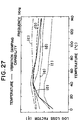
- Fig. 27 shows a loss factor ( ⁇ ) - temperature curve obtained by the experimental example described above.
- the vibration damping effect depicts a sharper peak with increasing number of spot connections and on the other hand, in the case where the number of spot connections decreases extremely, the vibration damping effect is lost rapidly.
- the contacting part between the plate member and the unconstrained vibration damping structure exists only in the neighborhood of the spot connected portion and they are almost not in contact with each other. Therefore no Coulomb friction can be produced and the vibration damping effect decreases rapidly.
- Fig. 28 shows loss factor ( ⁇ ) - temperature curves comparing the experimental examples described previously with experimental examples for comparison indicated below.
- thermosetting adhesive For adhesion of the plate member described above, phenol type thermosetting adhesive is used for obtaining strong adhesion.
- unconstrained vibration damping structure Since the part of unconstrained vibration damping structure is made of one steel plate, it can be processed without giving rise to break, etc. by a prior art embossing fabrication method. However the vibration damping effect is greatest in the neighborhood of 50°C due to the dynamic visco-elastic layer made of rubber and although the peak is somewhat broader than that obtained in EXPERIMENTAL EXAMPLE FOR COMPARISON 1, it is lower in level around it.
- the present invention in spite of the fact that it is so thin and has a rigidity so high that it disproves conventional common sense, not only it can realize a vibration isolation and sound insulation property higher than that obtained by a prior art vibration isolation rubber, but also for the torque transmissibility the rotational angle till a predetermined torque can be suppressed to 1/3 to 1/6 and for the long term creep resistant property the amount of variation in thickness can be reduced to 1/3 to 1/10.
- the exposed surface of rubber is small, it is possible to obtain an epoch-making vibration isolation washer, which can realize an overwhelmingly good environment resistant property.
- the vibration damping effect thereof depends strongly on the dynamic visco-elasticity of the constrained macromolecular visco-elastic layer.
- temperature characteristics of the vibration damping effect thus obtained has a large peak in the neighborhood of the glass transition point of the macromolecular visco-elastic body, only an extremely small vibration damping effect can be obtained in lower and higher temperature regions and it cannot be fit for use, particularly in the case where it is used in a wide temperature region from the room temperature (20°C) to a high temperature (150°C) as in the neighborhood of an engine for an automobile.
- an apparent constrained vibration damping structure can be obtained by binding the plate-shaped member to the unconstrained vibration damping construction in one body by spot connections such as rivet, screw, caulking, spot welding, etc. without adhesion. It can be said that this is a point, where the present invention differs remarkably from prior art techniques.
- the vibration damping effect Since the Coulomb friction does not depend in principle on temperature, if it is in a temperature region where the Coulomb friction effect of the macromolecular visco-elastic body is maintained, the vibration damping effect is kept almost constant and as the result, it can exhibit the vibration damping effect in a wide temperature region.
- the vibration damping effect is kept constant, it has no remarkable peak at a certain temperature, which is found for a prior art vibration damping steel plate, and the constrained vibration damping structure is more advantageous at that temperature.
- the effect should be exhibited in a wide temperature region as around an engine for a vehicle, etc., it is the best way to utilize the vibration damping by friction described above.
- a sealing and a vibration damping function can be utilized in common by utilizing a sealing function of the surface of the macromolecular visco-elastic layer, using the pressed construction, in which a macromolecular visco-elastic layer or such layers are formed on an inner surface or both surfaces of a metal plate.
Landscapes
- Engineering & Computer Science (AREA)
- General Engineering & Computer Science (AREA)
- Mechanical Engineering (AREA)
- Architecture (AREA)
- Bolts, Nuts, And Washers (AREA)
- Vibration Prevention Devices (AREA)
- Laminated Bodies (AREA)
Applications Claiming Priority (4)
| Application Number | Priority Date | Filing Date | Title |
|---|---|---|---|
| JP10347793 | 1993-04-05 | ||
| JP103477/93 | 1993-04-05 | ||
| JP20555893A JP3672330B2 (ja) | 1993-04-05 | 1993-07-29 | 制振構造体 |
| JP205558/93 | 1993-07-29 |
Publications (2)
| Publication Number | Publication Date |
|---|---|
| EP0619441A1 true EP0619441A1 (de) | 1994-10-12 |
| EP0619441B1 EP0619441B1 (de) | 1998-09-02 |
Family
ID=26444116
Family Applications (1)
| Application Number | Title | Priority Date | Filing Date |
|---|---|---|---|
| EP94400710A Expired - Lifetime EP0619441B1 (de) | 1993-04-05 | 1994-03-31 | Vorrichtung zur Dämpfung von Vibrationen und Verfahren zu dessen Herstellung |
Country Status (4)
| Country | Link |
|---|---|
| US (1) | US5489180A (de) |
| EP (1) | EP0619441B1 (de) |
| JP (1) | JP3672330B2 (de) |
| DE (1) | DE69412889T2 (de) |
Cited By (8)
| Publication number | Priority date | Publication date | Assignee | Title |
|---|---|---|---|---|
| WO1995027975A1 (de) * | 1994-04-06 | 1995-10-19 | Z^¿Db A.S. | Schwingungs- und schalldämpfer |
| WO2008144321A3 (en) * | 2007-05-17 | 2009-05-07 | Boeing Co | Hybrid contoured load-spreading washer |
| US8317173B2 (en) | 2006-09-22 | 2012-11-27 | Bridgestone Corporation | Vibration damping system |
| US8528874B2 (en) | 2007-05-17 | 2013-09-10 | The Boeing Company | Hybrid contoured load-spreading washer |
| DE102014016276A1 (de) * | 2014-11-05 | 2016-05-12 | Thyssenkrupp Ag | Anschlagdämpfer |
| CN106194956A (zh) * | 2016-08-28 | 2016-12-07 | 威腾电气集团股份有限公司 | 一种新型防水螺栓结构 |
| US10045519B2 (en) * | 2015-04-09 | 2018-08-14 | Shimano Components (Malaysia) Sdn. Bhd. | Washer for fishing reel |
| CN111702910A (zh) * | 2020-08-11 | 2020-09-25 | 周玉珍 | 一种木块与木板的无痕连接装置 |
Families Citing this family (53)
| Publication number | Priority date | Publication date | Assignee | Title |
|---|---|---|---|---|
| US5833038A (en) * | 1995-11-01 | 1998-11-10 | Sheiba; Lev Solomon | Method and apparatus for broadband earthquake resistant foundation with variable stiffness |
| GB2310694B (en) * | 1996-02-27 | 1999-12-08 | Aisin Seiki | Disc brake assembly |
| US6129326A (en) * | 1997-03-07 | 2000-10-10 | Caterpillar Inc. | Adhesive shock absorber |
| EP1034090B1 (de) | 1997-11-12 | 2003-12-17 | Collins & Aikman Products Co. | Vibrationsdämpfendes verbundmaterial |
| USD414406S (en) | 1998-02-18 | 1999-09-28 | Illinois Tool Works Inc. | Washer assembly |
| DE10030300A1 (de) * | 2000-06-27 | 2002-01-10 | Alfa Laval Flow Gmbh | Klappendichtung |
| CA2446498A1 (en) * | 2001-05-09 | 2002-11-14 | Damptech Aps | Frictional damper for damping movement of structures |
| JP2004053008A (ja) * | 2002-05-31 | 2004-02-19 | Fukoku Co Ltd | ビスカスダンパ |
| US7935118B2 (en) * | 2002-06-21 | 2011-05-03 | Depuy Products, Inc. | Prosthesis removal cutting guide, cutting tool and method |
| US20030236522A1 (en) * | 2002-06-21 | 2003-12-25 | Jack Long | Prosthesis cavity cutting guide, cutting tool and method |
| JP2005212220A (ja) * | 2004-01-28 | 2005-08-11 | Sanwa Packing Kogyo Co Ltd | 制振材料 |
| JP5022571B2 (ja) * | 2005-03-25 | 2012-09-12 | ニチアス株式会社 | ガスケット及びワッシャーの製造方法 |
| JP2009501350A (ja) * | 2005-07-14 | 2009-01-15 | カール・ツァイス・エスエムティー・アーゲー | 光学素子 |
| JP5015465B2 (ja) * | 2006-01-31 | 2012-08-29 | 株式会社ブリヂストン | 防振装置 |
| US8092129B2 (en) | 2006-04-21 | 2012-01-10 | Hubbell Incorporated | Bonding washer |
| DE102007041484A1 (de) * | 2007-08-31 | 2009-03-05 | Thyssenkrupp Steel Ag | Schwingungsdämpfendes Verbundbauteil |
| US8091609B2 (en) * | 2008-01-04 | 2012-01-10 | GM Global Technology Operations LLC | Method of forming casting with frictional damping insert |
| US7878747B2 (en) * | 2008-07-22 | 2011-02-01 | The Boeing Company | Insulating cover for fasteners used in high temperature environments |
| US8047753B2 (en) | 2008-07-22 | 2011-11-01 | The Boeing Company | Insulating washers |
| KR20110048052A (ko) | 2008-08-18 | 2011-05-09 | 프로덕티브 리서치 엘엘씨 | 성형가능한 경량 복합체 |
| JP5289163B2 (ja) * | 2009-04-24 | 2013-09-11 | 株式会社ブリヂストン | 免震構造体用プラグ及び免震構造体 |
| JP5571344B2 (ja) * | 2009-09-25 | 2014-08-13 | 矢崎総業株式会社 | ネジ締め締結構造 |
| US8796580B2 (en) * | 2009-12-28 | 2014-08-05 | Productive Research | Processes for welding composite materials and articles therefrom |
| KR102032405B1 (ko) | 2010-02-15 | 2019-10-16 | 프로덕티브 리서치 엘엘씨 | 성형가능한 경량 복합 재료 시스템 및 방법 |
| KR20140047033A (ko) | 2011-02-21 | 2014-04-21 | 프로덕티브 리서치 엘엘씨 | 특성이 다른 영역들을 포함하는 합성 재료들 및 방법들 |
| US8402702B1 (en) * | 2011-04-01 | 2013-03-26 | Roberto Villaverde | Aseismic sliding isolation system using hydromagnetic bearings |
| CN102691739B (zh) * | 2012-06-11 | 2013-09-18 | 谭晓婧 | 双出杆磁流变弹性体矩形减振器 |
| JP5977096B2 (ja) * | 2012-06-22 | 2016-08-24 | 株式会社Ihi | 結合構造体 |
| US9233526B2 (en) | 2012-08-03 | 2016-01-12 | Productive Research Llc | Composites having improved interlayer adhesion and methods thereof |
| JP6161448B2 (ja) * | 2013-07-17 | 2017-07-12 | アズビル株式会社 | 超音波流量計及び超音波流量計用の超音波吸収体 |
| US20150354663A1 (en) * | 2014-06-05 | 2015-12-10 | Hyundai Motor Company | Engine cover for absorbing vibration and assembling method thereof |
| MX2017002864A (es) * | 2014-09-04 | 2017-05-30 | Dana Automotive Systems Group | Junta. |
| KR102298871B1 (ko) * | 2015-12-11 | 2021-09-06 | 현대자동차 주식회사 | 와셔 및 이를 포함하는 체결 구조 |
| US9897133B2 (en) * | 2016-04-18 | 2018-02-20 | Linkwin Technology Co., Ltd. | Carbon fiber washer |
| US10648734B2 (en) * | 2016-10-14 | 2020-05-12 | Gala Industries, Inc. | Centrifugal pellet dryer |
| JP6792429B2 (ja) * | 2016-11-25 | 2020-11-25 | ナカ工業株式会社 | 回動式手摺り装置 |
| GB2559403B (en) * | 2017-02-06 | 2022-06-01 | Short Brothers Plc | Aircraft electrical isolation component and method of manufacturing electrical isolation component |
| RU2652165C1 (ru) * | 2017-06-14 | 2018-04-25 | Олег Савельевич Кочетов | Стенд для акустических испытаний звукопоглотителей |
| DE102018213305A1 (de) | 2018-08-08 | 2020-02-13 | Siemens Aktiengesellschaft | Vorrichtung und Verfahren zur Schwingungsdämpfung in Hochspannungseinrichtungen |
| CN109103017B (zh) * | 2018-08-28 | 2023-09-26 | 桂林电子科技大学 | 用于电力电容器减振降噪的金属橡胶减振器及其设置方法 |
| DE102018123870A1 (de) * | 2018-09-27 | 2020-04-02 | Schaeffler Technologies AG & Co. KG | Kraftfahrzeuggetriebe |
| WO2020092250A1 (en) | 2018-10-29 | 2020-05-07 | Hubbell Incorporated | Bonding washer |
| US11338552B2 (en) | 2019-02-15 | 2022-05-24 | Productive Research Llc | Composite materials, vehicle applications and methods thereof |
| DE102019106972A1 (de) * | 2019-03-19 | 2020-09-24 | Max Bögl Wind AG | Flachgegründetes Fundament für ein Bauteil |
| CN115004480A (zh) | 2019-12-30 | 2022-09-02 | 哈勃股份有限公司 | 结合夹具 |
| DE102020128549A1 (de) * | 2020-10-29 | 2022-05-05 | Böllhoff Verbindungstechnik GmbH | Dämpfungsanordnung, Bauteil mit Dämpfungsanordnung sowie entsprechende Bauteilverbindung, ein Herstellungsverfahren und ein Verbindungsverfahren |
| CN114688192A (zh) * | 2022-03-28 | 2022-07-01 | 中国重汽集团济南动力有限公司 | 一种重型汽车用金属橡胶支座减振器 |
| CN116512620A (zh) * | 2022-07-23 | 2023-08-01 | 浙江天铁实业股份有限公司 | 道床用谐振板及其制作方法和应用 |
| US12533523B2 (en) | 2022-10-07 | 2026-01-27 | Greatbatch Ltd. | High-voltage electrically insulating designs for use in active implantable medical devices |
| US11980766B2 (en) | 2022-10-07 | 2024-05-14 | Greatbatch Ltd. | Shaped insulating washer that prevents misalignment when positioned between a filter capacitor and a feedthrough |
| US12246183B1 (en) | 2023-10-06 | 2025-03-11 | Greatbatch Ltd. | Self-centering polymeric washer that prevents misalignment when positioned between a feedthrough and a circuit board supporting EMI filter capacitors for a medical device |
| US20260016043A1 (en) * | 2024-07-15 | 2026-01-15 | Carbice Corporation | Coated connector devices and methods of making and using thereof |
| KR102857058B1 (ko) * | 2024-10-31 | 2025-09-10 | 유한회사 만성스틸 | 열교환기용 지그 프레임 |
Citations (3)
| Publication number | Priority date | Publication date | Assignee | Title |
|---|---|---|---|---|
| US4198037A (en) * | 1976-12-28 | 1980-04-15 | Miner Enterprises, Inc. | Method of making polyester elastomer compression spring and resulting product |
| US4953658A (en) * | 1989-06-07 | 1990-09-04 | Ohbayashi Corporation | Seismic isolator |
| EP0510974A1 (de) * | 1991-04-24 | 1992-10-28 | Nichias Corporation | Schwingungsdämpfendes Material |
Family Cites Families (9)
| Publication number | Priority date | Publication date | Assignee | Title |
|---|---|---|---|---|
| DE3018818A1 (de) * | 1980-05-16 | 1981-11-26 | Hochtemperatur-Reaktorbau GmbH, 5000 Köln | Stuetzkonstruktion fuer einen vorgespannten zylindrischen druckbehaelter |
| JPS5783254A (en) * | 1980-11-12 | 1982-05-25 | Nippon Nousan Kogyo Kk | Feed for animal |
| NZ201015A (en) * | 1982-06-18 | 1986-05-09 | New Zealand Dev Finance | Building support:cyclic shear energy absorber |
| JPS6081511A (ja) * | 1983-10-06 | 1985-05-09 | 住友電気工業株式会社 | ワツシヤ |
| US4978581A (en) * | 1986-02-07 | 1990-12-18 | Bridgestone Construction | Anti-seismic bearing |
| US4761925A (en) * | 1986-03-31 | 1988-08-09 | Bridgestone Corporation | Anti-seismic rubber bearing |
| US4899323A (en) * | 1986-08-04 | 1990-02-06 | Bridgestone Corporation | Anti-seismic device |
| JP2589727B2 (ja) * | 1988-01-26 | 1997-03-12 | 株式会社ブリヂストン | 免震ゴム |
| US5014474A (en) * | 1989-04-24 | 1991-05-14 | Fyfe Edward R | System and apparatus for limiting the effect of vibrations between a structure and its foundation |
-
1993
- 1993-07-29 JP JP20555893A patent/JP3672330B2/ja not_active Expired - Lifetime
-
1994
- 1994-03-31 DE DE69412889T patent/DE69412889T2/de not_active Expired - Lifetime
- 1994-03-31 US US08/221,069 patent/US5489180A/en not_active Expired - Lifetime
- 1994-03-31 EP EP94400710A patent/EP0619441B1/de not_active Expired - Lifetime
Patent Citations (3)
| Publication number | Priority date | Publication date | Assignee | Title |
|---|---|---|---|---|
| US4198037A (en) * | 1976-12-28 | 1980-04-15 | Miner Enterprises, Inc. | Method of making polyester elastomer compression spring and resulting product |
| US4953658A (en) * | 1989-06-07 | 1990-09-04 | Ohbayashi Corporation | Seismic isolator |
| EP0510974A1 (de) * | 1991-04-24 | 1992-10-28 | Nichias Corporation | Schwingungsdämpfendes Material |
Cited By (13)
| Publication number | Priority date | Publication date | Assignee | Title |
|---|---|---|---|---|
| AT406098B (de) * | 1994-04-06 | 2000-02-25 | Zdb A S | Schwingungs- und schalldämpfer |
| WO1995027975A1 (de) * | 1994-04-06 | 1995-10-19 | Z^¿Db A.S. | Schwingungs- und schalldämpfer |
| US8317173B2 (en) | 2006-09-22 | 2012-11-27 | Bridgestone Corporation | Vibration damping system |
| US8528874B2 (en) | 2007-05-17 | 2013-09-10 | The Boeing Company | Hybrid contoured load-spreading washer |
| CN101675257B (zh) * | 2007-05-17 | 2012-07-04 | 波音公司 | 混合仿形负载分散垫圈 |
| US8511034B2 (en) | 2007-05-17 | 2013-08-20 | The Boeing Company | Hybrid contoured load-spreading washer |
| WO2008144321A3 (en) * | 2007-05-17 | 2009-05-07 | Boeing Co | Hybrid contoured load-spreading washer |
| DE102014016276A1 (de) * | 2014-11-05 | 2016-05-12 | Thyssenkrupp Ag | Anschlagdämpfer |
| CN107076241A (zh) * | 2014-11-05 | 2017-08-18 | 蒂森克虏伯普利斯坦股份公司 | 止挡减震器 |
| CN107076241B (zh) * | 2014-11-05 | 2020-03-24 | 蒂森克虏伯普利斯坦股份公司 | 止挡减震器 |
| US10045519B2 (en) * | 2015-04-09 | 2018-08-14 | Shimano Components (Malaysia) Sdn. Bhd. | Washer for fishing reel |
| CN106194956A (zh) * | 2016-08-28 | 2016-12-07 | 威腾电气集团股份有限公司 | 一种新型防水螺栓结构 |
| CN111702910A (zh) * | 2020-08-11 | 2020-09-25 | 周玉珍 | 一种木块与木板的无痕连接装置 |
Also Published As
| Publication number | Publication date |
|---|---|
| US5489180A (en) | 1996-02-06 |
| DE69412889D1 (de) | 1998-10-08 |
| DE69412889T2 (de) | 1999-05-12 |
| EP0619441B1 (de) | 1998-09-02 |
| JPH06341488A (ja) | 1994-12-13 |
| JP3672330B2 (ja) | 2005-07-20 |
Similar Documents
| Publication | Publication Date | Title |
|---|---|---|
| EP0619441B1 (de) | Vorrichtung zur Dämpfung von Vibrationen und Verfahren zu dessen Herstellung | |
| EP0510974B1 (de) | Schwingungsdämpfendes Material | |
| US12042884B2 (en) | Laminate including aluminum sheets | |
| US5842546A (en) | Split backplate for noise suppression in brake pad assemblies | |
| EP0335642B1 (de) | Schwingungdämmstoffe und ihre Anwendung für Schalldämmstrukturen | |
| US10520264B2 (en) | Cooling device for a vehicle battery, vehicle battery assembly, and method for producing a cooling device | |
| CN103547485B (zh) | 具有多层消声补片的面板组件 | |
| WO2000001524A1 (en) | Damped laminates having welded through holes and/or edges with decreased spring back and improved fastener force retention, and a method of making | |
| EP0807773B1 (de) | Schichtkörperdichtung | |
| KR101641383B1 (ko) | 개선된 진동 음향 댐핑 특성을 갖는 글레이징, 이러한 글레이징의 제조 방법, 및 차량 객실 내의 방음 방법 | |
| CN102782359B (zh) | 隔振结构体 | |
| CN110792337B (zh) | 具备带有振动阻尼组件的车辆撞销的机动车辆用闭合系统 | |
| KR20040033304A (ko) | 진동 댐핑 물질 | |
| JP2009108912A (ja) | ダイナミックダンパ及びダイナミックダンパ構成部材の組合せ構造体 | |
| CA2137954A1 (en) | Resonance absorber | |
| JP4948763B2 (ja) | ダンピングコイルばね及び振動減衰装置 | |
| KR100475127B1 (ko) | 스토퍼를 구비한 방진 장치 | |
| US7094478B1 (en) | Magnetic damping | |
| KR20020080212A (ko) | 진동감쇄능이 우수한 복층 금속판재 | |
| JP4418664B2 (ja) | オイルパン及びオイルパン用ガスケット | |
| JP7233534B2 (ja) | ディスクブレーキ用シムおよびディスクブレーキ | |
| JP2012237412A (ja) | 振動構造体 | |
| US7401690B2 (en) | Damped clutch plate system and method | |
| CN222483537U (zh) | 一种底护板、电池包框架、电池包及用电设备 | |
| CN215567510U (zh) | 一种制动器消音片 |
Legal Events
| Date | Code | Title | Description |
|---|---|---|---|
| PUAI | Public reference made under article 153(3) epc to a published international application that has entered the european phase |
Free format text: ORIGINAL CODE: 0009012 |
|
| AK | Designated contracting states |
Kind code of ref document: A1 Designated state(s): DE FR GB |
|
| 17P | Request for examination filed |
Effective date: 19950401 |
|
| 17Q | First examination report despatched |
Effective date: 19960410 |
|
| GRAG | Despatch of communication of intention to grant |
Free format text: ORIGINAL CODE: EPIDOS AGRA |
|
| GRAG | Despatch of communication of intention to grant |
Free format text: ORIGINAL CODE: EPIDOS AGRA |
|
| GRAH | Despatch of communication of intention to grant a patent |
Free format text: ORIGINAL CODE: EPIDOS IGRA |
|
| GRAH | Despatch of communication of intention to grant a patent |
Free format text: ORIGINAL CODE: EPIDOS IGRA |
|
| GRAA | (expected) grant |
Free format text: ORIGINAL CODE: 0009210 |
|
| AK | Designated contracting states |
Kind code of ref document: B1 Designated state(s): DE FR GB |
|
| REF | Corresponds to: |
Ref document number: 69412889 Country of ref document: DE Date of ref document: 19981008 |
|
| ET | Fr: translation filed | ||
| PLBE | No opposition filed within time limit |
Free format text: ORIGINAL CODE: 0009261 |
|
| STAA | Information on the status of an ep patent application or granted ep patent |
Free format text: STATUS: NO OPPOSITION FILED WITHIN TIME LIMIT |
|
| 26N | No opposition filed | ||
| REG | Reference to a national code |
Ref country code: GB Ref legal event code: IF02 |
|
| PGFP | Annual fee paid to national office [announced via postgrant information from national office to epo] |
Ref country code: GB Payment date: 20130327 Year of fee payment: 20 Ref country code: FR Payment date: 20130325 Year of fee payment: 20 Ref country code: DE Payment date: 20130327 Year of fee payment: 20 |
|
| REG | Reference to a national code |
Ref country code: DE Ref legal event code: R071 Ref document number: 69412889 Country of ref document: DE |
|
| REG | Reference to a national code |
Ref country code: DE Ref legal event code: R071 Ref document number: 69412889 Country of ref document: DE |
|
| REG | Reference to a national code |
Ref country code: GB Ref legal event code: PE20 Expiry date: 20140330 |
|
| PG25 | Lapsed in a contracting state [announced via postgrant information from national office to epo] |
Ref country code: GB Free format text: LAPSE BECAUSE OF EXPIRATION OF PROTECTION Effective date: 20140330 |
|
| PG25 | Lapsed in a contracting state [announced via postgrant information from national office to epo] |
Ref country code: DE Free format text: LAPSE BECAUSE OF EXPIRATION OF PROTECTION Effective date: 20140401 |