EP0619444A1 - Différentiel de blocage variable - Google Patents
Différentiel de blocage variable Download PDFInfo
- Publication number
- EP0619444A1 EP0619444A1 EP94103474A EP94103474A EP0619444A1 EP 0619444 A1 EP0619444 A1 EP 0619444A1 EP 94103474 A EP94103474 A EP 94103474A EP 94103474 A EP94103474 A EP 94103474A EP 0619444 A1 EP0619444 A1 EP 0619444A1
- Authority
- EP
- European Patent Office
- Prior art keywords
- clutch
- clutch means
- differential gear
- inactive
- pyrolytic carbon
- Prior art date
- Legal status (The legal status is an assumption and is not a legal conclusion. Google has not performed a legal analysis and makes no representation as to the accuracy of the status listed.)
- Granted
Links
- 239000002296 pyrolytic carbon Substances 0.000 claims abstract description 38
- 239000002783 friction material Substances 0.000 claims abstract description 33
- 230000000694 effects Effects 0.000 claims abstract description 10
- 230000007246 mechanism Effects 0.000 claims description 47
- 230000009471 action Effects 0.000 claims description 16
- 229910000831 Steel Inorganic materials 0.000 claims description 7
- 239000010959 steel Substances 0.000 claims description 7
- 230000004044 response Effects 0.000 claims description 4
- 239000000463 material Substances 0.000 claims description 3
- 230000003247 decreasing effect Effects 0.000 description 10
- 230000000979 retarding effect Effects 0.000 description 9
- 230000000630 rising effect Effects 0.000 description 5
- 229910000975 Carbon steel Inorganic materials 0.000 description 4
- 230000007423 decrease Effects 0.000 description 4
- 238000010276 construction Methods 0.000 description 3
- OKTJSMMVPCPJKN-UHFFFAOYSA-N Carbon Chemical compound [C] OKTJSMMVPCPJKN-UHFFFAOYSA-N 0.000 description 2
- JJLJMEJHUUYSSY-UHFFFAOYSA-L Copper hydroxide Chemical compound [OH-].[OH-].[Cu+2] JJLJMEJHUUYSSY-UHFFFAOYSA-L 0.000 description 2
- 230000004075 alteration Effects 0.000 description 2
- 229910052799 carbon Inorganic materials 0.000 description 2
- 239000011248 coating agent Substances 0.000 description 2
- 238000000576 coating method Methods 0.000 description 2
- 238000012986 modification Methods 0.000 description 2
- 230000004048 modification Effects 0.000 description 2
- 239000000758 substrate Substances 0.000 description 2
- 229920000049 Carbon (fiber) Polymers 0.000 description 1
- 230000005540 biological transmission Effects 0.000 description 1
- 239000004917 carbon fiber Substances 0.000 description 1
- 238000005229 chemical vapour deposition Methods 0.000 description 1
- 230000004069 differentiation Effects 0.000 description 1
- 239000000835 fiber Substances 0.000 description 1
- 230000013011 mating Effects 0.000 description 1
- 230000007935 neutral effect Effects 0.000 description 1
- 238000009877 rendering Methods 0.000 description 1
- 239000011435 rock Substances 0.000 description 1
- 239000007787 solid Substances 0.000 description 1
Images


Classifications
-
- F—MECHANICAL ENGINEERING; LIGHTING; HEATING; WEAPONS; BLASTING
- F16—ENGINEERING ELEMENTS AND UNITS; GENERAL MEASURES FOR PRODUCING AND MAINTAINING EFFECTIVE FUNCTIONING OF MACHINES OR INSTALLATIONS; THERMAL INSULATION IN GENERAL
- F16H—GEARING
- F16H48/00—Differential gearings
- F16H48/06—Differential gearings with gears having orbital motion
- F16H48/08—Differential gearings with gears having orbital motion comprising bevel gears
-
- F—MECHANICAL ENGINEERING; LIGHTING; HEATING; WEAPONS; BLASTING
- F16—ENGINEERING ELEMENTS AND UNITS; GENERAL MEASURES FOR PRODUCING AND MAINTAINING EFFECTIVE FUNCTIONING OF MACHINES OR INSTALLATIONS; THERMAL INSULATION IN GENERAL
- F16H—GEARING
- F16H48/00—Differential gearings
- F16H48/20—Arrangements for suppressing or influencing the differential action, e.g. locking devices
- F16H48/22—Arrangements for suppressing or influencing the differential action, e.g. locking devices using friction clutches or brakes
-
- F—MECHANICAL ENGINEERING; LIGHTING; HEATING; WEAPONS; BLASTING
- F16—ENGINEERING ELEMENTS AND UNITS; GENERAL MEASURES FOR PRODUCING AND MAINTAINING EFFECTIVE FUNCTIONING OF MACHINES OR INSTALLATIONS; THERMAL INSULATION IN GENERAL
- F16H—GEARING
- F16H48/00—Differential gearings
- F16H48/20—Arrangements for suppressing or influencing the differential action, e.g. locking devices
- F16H48/24—Arrangements for suppressing or influencing the differential action, e.g. locking devices using positive clutches or brakes
-
- F—MECHANICAL ENGINEERING; LIGHTING; HEATING; WEAPONS; BLASTING
- F16—ENGINEERING ELEMENTS AND UNITS; GENERAL MEASURES FOR PRODUCING AND MAINTAINING EFFECTIVE FUNCTIONING OF MACHINES OR INSTALLATIONS; THERMAL INSULATION IN GENERAL
- F16H—GEARING
- F16H48/00—Differential gearings
- F16H48/38—Constructional details
- F16H2048/382—Methods for manufacturing differential gearings
Definitions
- the present invention relates to differential gear mechanisms, and more particularly, to such mechanisms of the type commonly referred to as "locking differentials".
- Differential gear mechanisms of the general type to which the present invention relates are broadly referred to as “limited slip differentials", and typically include a clutch pack which is operable to limit or retard differentiating action between the output gears (sidegears). More specifically, however, the present invention is intended for use on limited slips of the type referred to as “locking differentials", and will be described in connection therewith.
- a locking differential means are provided for engaging or locking the clutch set, rather than permitting it to slip (i.e., the slip is "limited” to the point of being nonexistent), thus substantially eliminating differentiating action between the output gears.
- Locking differentials are produced and sold commercially by the assignee of the present invention, with the construction and operation of such locking differentials being illustrated and described in great detail in U.S. Patent No. 4,389,909, assigned to the assignee of the present invention and incorporated herein by reference.
- a flyweight mechanism which rotates about its axis of rotation at a speed representative of the differential speed between the two output gears. Above a predetermined rotational speed (speed of differentiation), the flyweight mechanism is actuated to cause ramping of a cam member relative to another cam member. This ramping action of the cam members results in axial movement of the one cam member, which initiates engagement of an adjacent clutch pack.
- the clutch pack is of the "self-actuating" type, i.e., a small amount of frictional engagement within the clutch pack further retards rotation of the adjacent cam member, resulting in further ramping action, which, in turn, causes further axial movement of the cam member and further engagement of the clutch pack.
- the clutch pack immediately adjacent the cam arrangement includes two types of clutch discs:
- One of the key performance criteria of a locking differential is the "time of engagement" of the mechanism, which is the period of time ( ⁇ T) required for the clutch pack to go from a predetermined, lower torque transmitting capacity to a predetermined, higher torque transmitting capacity.
- ⁇ T period of time
- the time of engagement was based upon the ⁇ T from 100 foot-pounds of torque capacity to 1000 foot-pounds of torque capacity.
- the cam angle i.e., the angle defined between the cam surface and the transverse plane.
- the clutch packs have typically comprised a plurality of stamped steel clutch discs, with the discs typically including some sort of pattern stamped into the disc face to enhance frictional engagement between adjacent disc surfaces.
- a differential gear mechanism of the type including a gear case defining a gear chamber, differential gear means disposed in the gear chamber, the differential gear means including at least one input gear and first and second output gears.
- a lock-up means is included for locking up the differential gear means to retard differentiating action.
- the lock-up means includes clutch means operable between an engaged condition, effective to retard relative rotation between the gear case and the output gears, and a disengaged condition.
- the lock-up means further includes cam means operatively associated with the clutch means, and including first and second cam members, the second cam member being axially movable relative to the first cam member in response to relative rotation therebetween, to effect the engaged condition of the clutch means.
- the clutch means comprises active clutch means disposed immediately adjacent the second cam member and operable to effect the time of engagement of the clutch means.
- the improved differential gear mechanism is characterized by the active clutch means comprising at least a pair of engaging clutch surfaces, with one of the pair of clutch surfaces comprising a pyrolytic carbon friction material and the other of the pair of clutch surfaces comprising a non-pyrolytic carbon friction material.
- the clutch means further comprises inactive clutch means operable to provide a major portion of the torque transmitting capacity of the clutch means.
- the inactive clutch means comprises a plurality of pairs of engaging clutch surfaces, all of the inactive clutch surfaces comprising non-pyrolytic carbon friction material.
- the improved differential gear mechanism is characterized by the non-pyrolytic friction material comprising a stamped, steel clutch disc.
- FIG. 1 is an axial cross-section of a locking differential mechanism of the type with which the present invention may be utilized.
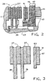
- FIG. 2 is an enlarged, fragmentary, axial cross-section, similar to FIG. 1, illustrating the clutch pack to which the present invention relates.
- FIG. 3 is a further enlarged, axial cross-section, similar to FIG. 2, but showing only the discs comprising the clutch pack.
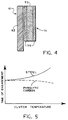
- FIG. 4 is a further enlarged, fragmentary, axial cross-section of only a pair of active clutch discs, illustrating the present invention.
- FIG. 5 is a graph of time of engagement versus clutch temperature, comparing the present invention with the prior art.
- FIG. 6 is a plan view of one of the cam members in use in the locking differential mechanism of the present invention.
- FIG. 7 is a fragmentary side view of the cam member shown in FIG. 6, but on a scale twice that of FIG. 6.
- FIG. 1 is an axial cross-section of a locking differential gear mechanism of the type which may advantageously utilize the present invention.
- the overall construction and operation of the locking differential shown in FIG. 1 is already well known to those skilled in the art, and is illustrated and described in greater detail in above-incorporated U.S. Patent No. 4,389,909.
- the differential gear mechanism includes a gear case 11 which defines therein a gear chamber, generally designated 13. Torque input to the locking differential is typically by means of an input gear 15 (shown only in fragmentary view in FIG. 1).
- the input gear 15 (also referred to as a "ring gear”) is intended to be in toothed engagement with an input pinion gear (not shown in FIG. 1).
- the input gear 15 may be attached to the gear case 11 by means of a plurality of bolts 17.
- a differential gear set including a plurality of pinions 19 (only one of which is shown in FIG. 1), rotatably mounted on a pinion shaft 21 (only a portion of which is shown in FIG. 1).
- the pinion shaft 21 is secured to the gear case 11 by any suitable means.
- the pinions 19 comprise the input gears of the differential gear set, and are in meshing engagement with a pair of side gears 23 and 25, which comprise the output gears of the differential gear set.
- the side gears 23 and 25 are splined to a pair of axle shafts 27 and 29, respectively.
- the gear case 11 includes annular hub portions 31 and 33, surrounding the axle shafts 27 and 29, respectively.
- bearing sets (not shown) are mounted on the hub portions 31 and 33 to provide rotational support for the differential gear mechanism, relative to the main, outer casing (also not shown in FIG. 1).
- the differential gear mechanism is provided with a lock-up means for locking up the differential gear set, and an actuating means for actuating the lock-up means.
- a lock-up means for locking up the differential gear set
- an actuating means for actuating the lock-up means.
- the general construction and operation of the lock-up means and the actuating means are now well known in the art, and will be described only briefly herein.
- U.S. Patent Nos. Re. 28,004, and 3,831,462 both of which are assigned to the assignee of the present invention, and both of which are incorporated herein by reference.
- the lock-up means comprises a clutch pack, generally designated 35 in FIG. 1.
- the clutch pack 35 includes a plurality of clutch discs 37, splined to the gear case 11, and a plurality of clutch discs 39, splined to the sidegear 23.
- the lock-up means further includes a cam mechanism, generally designated 41.
- the primary function of the cam mechanism 41 is to effect movement of the clutch pack 35 from the disengaged condition shown in FIG. 2 to an engaged condition (not shown herein). In the engaged condition, the clutch pack 35 is effective to retard relative rotation between the gear case 11 and the sidegear 23, thus retarding and minimizing differentiating action between the sidegears 23 and 25.
- the cam mechanism 41 includes the side gear 23 and a main cam member 43.
- the side gear 23 defines a cam surface 45
- the cam member 43 defines a cam surface 47 (see FIGS. 2, 6, and 7).
- the cam member 43 also defines a set of external teeth 49, the function of which will be described subsequently.
- the cam surfaces 45 and 47 remain in the neutral position shown in FIG. 1, with the cam member 43 rotating with the sidegear 23, at the same rotational speed. Movement of the clutch pack 35 to the engaged condition is accomplished by retarding rotation of the cam member 43, relative to the sidegear 23, which causes “ramping" of the cam surfaces 45 and 47, as is well known to those skilled in the art. This ramping results in axial movement of the cam member 43 to the left in FIG. 1, thus beginning the engagement of the clutch pack 35.
- the cam surface 47 comprises a plurality of alternating rising surface portions 47a and falling surface portions 47b. It should be clearly understood that the terms “rising” and “falling” are based upon an assumed counter-clockwise direction of travel around the cam member 43.
- Each of the rising surface portions 47a meets the next (in a counter-clockwise direction) falling surface portion 47b at a peak 47c, while being separated from the preceding falling surface portion 47b by a flat, valley surface 47d.
- Each of the rising surface portions 47a is provided with a pad portion 47e, while each of the falling surface portions 47b is provided with a pad portion 47f, the pad portions projecting slightly in an axial direction from the adjacent surface portion.
- each of the rising surface portions 47e and 47f define a cam angle A relative to a transverse surface.
- the mechanism In order to retard rotation of the cam member 43, relative to the sidegear 23, the mechanism includes a retarding mechanism, generally designated 51, which comprises the actuating means for actuating the lock-up means.
- a retarding mechanism generally designated 51
- the retarding mechanism 51 is of the flyweight type, illustrated and described in greater detail in above-incorporated U.S. Patent No. Re. 28,004.
- the retarding mechanism 51 is mounted within the gear case 11 for rotation about its own axis, and includes a cylindrical flyweight portion 53.
- the retarding mechanism 51 further includes an externally-geared portion 55 which is in engagement with the external gear teeth 49 of the cam member 43.
- a clutch pack including a plurality of clutch discs splined to the gear case 11, and a plurality of clutch discs splined to the sidegear 25.
- the individual clutch discs do not bear reference numerals.
- the clutch pack 57 will be understood as comprising inactive discs, as that term was defined in the BACKGROUND OF THE DISCLOSURE.
- all of the clutch discs 37 and 39 also comprise inactive discs.
- the inactive discs in the clutch pack 57 together with the inactive discs 37 and 39 in the clutch pack 35, transmit a major portion of the total torque which is transmitted from the gear case 11 to the sidegears 23 and 25.
- the torque capacity of clutch discs is generally proportional to the area of frictional engagement.
- the active disc pack 61 operably associated with the cam mechanism 41, and more specifically, operably associated with the main cam member 43.
- the active disc pack 61 includes a disc 63 which is in splined engagement with a set of external splines 65 defined by the main cam member 43, for rotation therewith. Disposed axially between the disc 63 and the main cam member 43 is a disc 67. Therefore, the discs 63 and 67 ( and sometimes, the adjacent disc 37) comprise the active discs.
- the structure which has been illustrated and described up to this point represents the conventional locking differential and active and inactive discs typically utilized therein.
- all of the discs in the inactive clutch packs 35 and 57, and in the active clutch pack 61 would comprise plain, stamped steel discs, perhaps including some sort of pattern stamped into the disc surface to enhance frictional engagement between adjacent disc surfaces.
- the active disc pack 61 comprises the disc 63 which is splined to the cam member 43.
- the plain steel disc 67 has been replaced with a disc assembly, generally designated 71.
- the disc assembly 71 comprises a disc member 73, which may be substantially identical to the disc 67 shown in FIG. 3, except that the disc member 73 would typically not have any sort of pattern stamped into either disc surface (i.e., into either the left surface or the right surface).
- pyrolytic carbon friction material 75 comprises a substrate formed of carbon fibers having a coating of carbon deposited on the fibers by chemical vapor deposition, such that the resulting friction material has a relatively open mesh so that the surface texture of the substrate is still discernable after the coating of carbon is applied.
- pyrolytic carbon friction material is described and illustrated in greater detail in U.S. Patent No. 4,700,823, assigned to the assignee of the present invention and incorporated herein by reference.
- pyrolytic carbon will mean any friction material of the type illustrated in, described in, or within the scope of the claims of, the above-incorporated U.S. Patent No. 4,700,823, or which provides the characteristic of the co-efficient of friction not substantially decreasing with increasing temperature. It is preferred, but not essential to the present invention, that the material which comprises "pyrolytic carbon" for purposes of the present invention has a coefficient of friction which actually increases with increasing temperature.
- non-pyrolytic carbon in reference to a friction material, a clutch disc, or a clutch surface, shall mean any such material, disc, or surface which does not comprise “pyrolytic carbon", as defined above. Therefore, in the embodiment of the present invention shown in FIG. 4, the clutch disc 63, which has been described by way of example only as a plain steel disc, would comprise a “non-pyrolytic carbon” disc, or would comprise a disc having "non-pyrolytic carbon" friction surfaces.
- the cam angle A was increased by approximately one degree for each disc member having pyrolytic carbon on its clutch surfaces. Therefore, as shown in FIG. 4, with only a single disc 73 having pyrolytic carbon, the cam angle A of the cam member 43 was increased from about 12.5 degrees to about 13.5 degrees. As is now well known to those skilled in the art, if the engagement of the clutch pack in a locking differential occurs too quickly, for example, in less than .1 seconds, the differential may cycle between the locked and the unlocked conditions.
Landscapes
- Engineering & Computer Science (AREA)
- General Engineering & Computer Science (AREA)
- Mechanical Engineering (AREA)
- Retarders (AREA)
Applications Claiming Priority (4)
| Application Number | Priority Date | Filing Date | Title |
|---|---|---|---|
| US2908393A | 1993-03-10 | 1993-03-10 | |
| US29083 | 1993-03-10 | ||
| US127391 | 1993-09-27 | ||
| US08/127,391 US5484347A (en) | 1993-03-10 | 1993-09-27 | Variable rate locking differential with pyrolitic-carbon friction clutch |
Publications (2)
| Publication Number | Publication Date |
|---|---|
| EP0619444A1 true EP0619444A1 (fr) | 1994-10-12 |
| EP0619444B1 EP0619444B1 (fr) | 1997-05-21 |
Family
ID=26704517
Family Applications (1)
| Application Number | Title | Priority Date | Filing Date |
|---|---|---|---|
| EP94103474A Expired - Lifetime EP0619444B1 (fr) | 1993-03-10 | 1994-03-08 | Différentiel de blocage variable |
Country Status (3)
| Country | Link |
|---|---|
| US (1) | US5484347A (fr) |
| EP (1) | EP0619444B1 (fr) |
| DE (1) | DE69403264T2 (fr) |
Cited By (1)
| Publication number | Priority date | Publication date | Assignee | Title |
|---|---|---|---|---|
| WO1996023144A1 (fr) * | 1995-01-23 | 1996-08-01 | Antonov Automotive Technologies B.V. | Dispositif d'accouplement multi-disques, transmission automatique ainsi equipee et procede de realisation |
Families Citing this family (18)
| Publication number | Priority date | Publication date | Assignee | Title |
|---|---|---|---|---|
| US5863271A (en) * | 1996-08-16 | 1999-01-26 | Hydro-Gear Limited Partnership | Controlled traction cartridge and differential |
| US5897452A (en) * | 1996-08-16 | 1999-04-27 | Hydro-Gear Limited Partnership | Integrated hydrostatic transaxle with controlled traction differential |
| US6122996A (en) | 1998-11-20 | 2000-09-26 | Hydro-Gear Limited Partnership | Hydrostatic transmission |
| US7454907B1 (en) | 1998-11-20 | 2008-11-25 | Hydro-Gear Limited Partnership | Hydrostatic transmission |
| JP3192639B2 (ja) * | 1999-04-08 | 2001-07-30 | 川崎重工業株式会社 | 車輌のブレーキ装置 |
| US6575868B1 (en) | 2000-04-14 | 2003-06-10 | Hydro-Gear Limited Partnership | Transaxle with differential lock mechanism |
| US6319166B1 (en) * | 2000-05-15 | 2001-11-20 | Eaton Corporation | Compact locking differential |
| US6780137B1 (en) | 2002-07-26 | 2004-08-24 | Hydro-Gear Limited Partnership | Differential lock mechanism |
| US7300379B2 (en) * | 2003-11-10 | 2007-11-27 | The Timken Company | Differential with thin film coating at cross shaft and processes for manufacturing the same |
| US7367913B2 (en) * | 2005-02-11 | 2008-05-06 | Team Industries, Inc. | Wet brake system for vehicles |
| DE102005029087A1 (de) | 2005-06-23 | 2007-01-04 | Dr.Ing.H.C. F. Porsche Ag | Lamellen-Sperrdifferential |
| US7438661B2 (en) | 2006-02-15 | 2008-10-21 | Eaton Corporation | Mechanical locking differential lockout mechanism |
| US20080058151A1 (en) * | 2006-09-01 | 2008-03-06 | Kent M. Curtis | Cam gear for mechanical locking differential |
| US8167763B2 (en) | 2009-04-20 | 2012-05-01 | Eaton Corporation | Block mounted lock-out mechanism |
| JP6291588B2 (ja) | 2013-10-15 | 2018-03-14 | イートン コーポレーションEaton Corporation | 機械式噛み合いロックディファレンシャル |
| CA2887514C (fr) | 2014-04-09 | 2023-05-23 | TAP Worldwide, LLC | Differentiel verrouillable |
| US11118664B2 (en) * | 2018-11-06 | 2021-09-14 | American Axle & Manufacturing, Inc. | Limited slip differential with clutch for inhibiting speed differentiation between side gears |
| KR102769435B1 (ko) | 2019-01-10 | 2025-02-19 | 이턴 인텔리전트 파워 리미티드 | 로크 플레이트를 갖는 클러치 팩 |
Citations (3)
| Publication number | Priority date | Publication date | Assignee | Title |
|---|---|---|---|---|
| US3831462A (en) * | 1972-03-16 | 1974-08-27 | Eaton Corp | Limited slip differential |
| EP0037104A2 (fr) * | 1980-03-28 | 1981-10-07 | Eaton Corporation | Embrayage à matière de friction en carbone pyrolytique |
| EP0332443A2 (fr) * | 1988-03-10 | 1989-09-13 | Eaton Corporation | Différentiel anti-patinage |
Family Cites Families (7)
| Publication number | Priority date | Publication date | Assignee | Title |
|---|---|---|---|---|
| US3932568A (en) * | 1973-06-26 | 1976-01-13 | Friction Products Inc. | High-energy brake and brake components |
| US4238013A (en) * | 1978-05-08 | 1980-12-09 | Eaton Corporation | Contact improver for clutch of a slip limiting differential |
| US4389909A (en) * | 1981-05-26 | 1983-06-28 | Eaton Corporation | Cam mechanism for limited slip or locking differential |
| DE3738949A1 (de) * | 1987-11-17 | 1989-05-24 | Textar Gmbh | Bremse fuer strassen-, schienen- und luftfahrzeuge |
| US5007886A (en) * | 1989-12-26 | 1991-04-16 | Eaton Corporation | Limited slip differential |
| US5083650A (en) * | 1991-05-24 | 1992-01-28 | Minnesota Mining And Manufacturing Company | Friction material having heat-resistant paper support bearing resin-bonded carbon particles |
| US5230952A (en) * | 1991-06-17 | 1993-07-27 | Coltec Industries Inc. | Sintered composite friction material comprising fluorocarbon resin |
-
1993
- 1993-09-27 US US08/127,391 patent/US5484347A/en not_active Expired - Lifetime
-
1994
- 1994-03-08 DE DE69403264T patent/DE69403264T2/de not_active Expired - Lifetime
- 1994-03-08 EP EP94103474A patent/EP0619444B1/fr not_active Expired - Lifetime
Patent Citations (3)
| Publication number | Priority date | Publication date | Assignee | Title |
|---|---|---|---|---|
| US3831462A (en) * | 1972-03-16 | 1974-08-27 | Eaton Corp | Limited slip differential |
| EP0037104A2 (fr) * | 1980-03-28 | 1981-10-07 | Eaton Corporation | Embrayage à matière de friction en carbone pyrolytique |
| EP0332443A2 (fr) * | 1988-03-10 | 1989-09-13 | Eaton Corporation | Différentiel anti-patinage |
Cited By (3)
| Publication number | Priority date | Publication date | Assignee | Title |
|---|---|---|---|---|
| WO1996023144A1 (fr) * | 1995-01-23 | 1996-08-01 | Antonov Automotive Technologies B.V. | Dispositif d'accouplement multi-disques, transmission automatique ainsi equipee et procede de realisation |
| US5860890A (en) * | 1995-01-23 | 1999-01-19 | Antonov Automotive Technologies B.V. | Multi-disc coupling device, an automatic transmission equipped therewith, and a manufacturing method therefor |
| AU711108B2 (en) * | 1995-01-23 | 1999-10-07 | Antonov Automotive Technologies B.V. | A multi-disc coupling device, an automatic transmission equipped therewith, and a manufacturing method therefor |
Also Published As
| Publication number | Publication date |
|---|---|
| EP0619444B1 (fr) | 1997-05-21 |
| DE69403264T2 (de) | 1997-11-20 |
| DE69403264D1 (de) | 1997-06-26 |
| US5484347A (en) | 1996-01-16 |
Similar Documents
| Publication | Publication Date | Title |
|---|---|---|
| EP0619444B1 (fr) | Différentiel de blocage variable | |
| US4389909A (en) | Cam mechanism for limited slip or locking differential | |
| US4022084A (en) | Control couplings | |
| US3831462A (en) | Limited slip differential | |
| US2971404A (en) | Locking differential | |
| US4400996A (en) | Positive clutch differential | |
| US5911643A (en) | Differential gear mechanism and improved ball-ramp actuation thereof | |
| EP0130806B1 (fr) | Mécanisme différentiel | |
| US6083134A (en) | Electronically actuated locking differential | |
| US8216106B2 (en) | Locking differential side gear to friction disc unloading | |
| US6537172B1 (en) | Electronically actuated modulatable differential | |
| US3517573A (en) | Centrifugally actuated locking differential | |
| JP2016538512A (ja) | 機械式噛み合いロックディファレンシャル | |
| GB2119040A (en) | Self-locking differential | |
| US4280375A (en) | Controlled differential | |
| EP2057391A1 (fr) | Engrenage à cames pour différentiel à blocage mécanique | |
| US4825724A (en) | Differential gear | |
| KR102750613B1 (ko) | 로크 플레이트를 갖는 클러치 팩 | |
| EP0016641B1 (fr) | Engrenage différentiel à verrouillage | |
| EP1304506B1 (fr) | Différentiel modulable commandé électroniquement | |
| KR19980087496A (ko) | 점성으로 액추에이트된 볼 램프 클러치 | |
| EP0107903B1 (fr) | Entraînement direct avec embrayage secondaire | |
| JP2559680Y2 (ja) | クラッチ | |
| KR20000011401A (ko) | 센터차동장치 | |
| JPH025942B2 (fr) |
Legal Events
| Date | Code | Title | Description |
|---|---|---|---|
| PUAI | Public reference made under article 153(3) epc to a published international application that has entered the european phase |
Free format text: ORIGINAL CODE: 0009012 |
|
| AK | Designated contracting states |
Kind code of ref document: A1 Designated state(s): DE FR GB IT SE |
|
| 17P | Request for examination filed |
Effective date: 19950329 |
|
| 17Q | First examination report despatched |
Effective date: 19960125 |
|
| GRAG | Despatch of communication of intention to grant |
Free format text: ORIGINAL CODE: EPIDOS AGRA |
|
| GRAH | Despatch of communication of intention to grant a patent |
Free format text: ORIGINAL CODE: EPIDOS IGRA |
|
| GRAH | Despatch of communication of intention to grant a patent |
Free format text: ORIGINAL CODE: EPIDOS IGRA |
|
| GRAA | (expected) grant |
Free format text: ORIGINAL CODE: 0009210 |
|
| AK | Designated contracting states |
Kind code of ref document: B1 Designated state(s): DE FR GB IT SE |
|
| REF | Corresponds to: |
Ref document number: 69403264 Country of ref document: DE Date of ref document: 19970626 |
|
| ET | Fr: translation filed | ||
| PLBE | No opposition filed within time limit |
Free format text: ORIGINAL CODE: 0009261 |
|
| STAA | Information on the status of an ep patent application or granted ep patent |
Free format text: STATUS: NO OPPOSITION FILED WITHIN TIME LIMIT |
|
| 26N | No opposition filed | ||
| REG | Reference to a national code |
Ref country code: GB Ref legal event code: IF02 |
|
| PGFP | Annual fee paid to national office [announced via postgrant information from national office to epo] |
Ref country code: IT Payment date: 20120320 Year of fee payment: 19 |
|
| PGFP | Annual fee paid to national office [announced via postgrant information from national office to epo] |
Ref country code: FR Payment date: 20130315 Year of fee payment: 20 Ref country code: SE Payment date: 20130308 Year of fee payment: 20 Ref country code: GB Payment date: 20130225 Year of fee payment: 20 |
|
| PGFP | Annual fee paid to national office [announced via postgrant information from national office to epo] |
Ref country code: DE Payment date: 20130328 Year of fee payment: 20 |
|
| REG | Reference to a national code |
Ref country code: DE Ref legal event code: R071 Ref document number: 69403264 Country of ref document: DE |
|
| REG | Reference to a national code |
Ref country code: GB Ref legal event code: PE20 Expiry date: 20140307 |
|
| REG | Reference to a national code |
Ref country code: SE Ref legal event code: EUG |
|
| PG25 | Lapsed in a contracting state [announced via postgrant information from national office to epo] |
Ref country code: GB Free format text: LAPSE BECAUSE OF EXPIRATION OF PROTECTION Effective date: 20140307 Ref country code: DE Free format text: LAPSE BECAUSE OF EXPIRATION OF PROTECTION Effective date: 20140311 |