EP0619629A2 - Verbindersystem für Kochplatten - Google Patents
Verbindersystem für Kochplatten Download PDFInfo
- Publication number
- EP0619629A2 EP0619629A2 EP94500024A EP94500024A EP0619629A2 EP 0619629 A2 EP0619629 A2 EP 0619629A2 EP 94500024 A EP94500024 A EP 94500024A EP 94500024 A EP94500024 A EP 94500024A EP 0619629 A2 EP0619629 A2 EP 0619629A2
- Authority
- EP
- European Patent Office
- Prior art keywords
- support
- connector
- terminals
- cavities
- conductor cables
- Prior art date
- Legal status (The legal status is an assumption and is not a legal conclusion. Google has not performed a legal analysis and makes no representation as to the accuracy of the status listed.)
- Granted
Links
Images
Classifications
-
- H—ELECTRICITY
- H05—ELECTRIC TECHNIQUES NOT OTHERWISE PROVIDED FOR
- H05B—ELECTRIC HEATING; ELECTRIC LIGHT SOURCES NOT OTHERWISE PROVIDED FOR; CIRCUIT ARRANGEMENTS FOR ELECTRIC LIGHT SOURCES, IN GENERAL
- H05B3/00—Ohmic-resistance heating
- H05B3/68—Heating arrangements specially adapted for cooking plates or analogous hot-plates
- H05B3/74—Non-metallic plates, e.g. vitroceramic, ceramic or glassceramic hobs, also including power or control circuits
-
- H—ELECTRICITY
- H05—ELECTRIC TECHNIQUES NOT OTHERWISE PROVIDED FOR
- H05B—ELECTRIC HEATING; ELECTRIC LIGHT SOURCES NOT OTHERWISE PROVIDED FOR; CIRCUIT ARRANGEMENTS FOR ELECTRIC LIGHT SOURCES, IN GENERAL
- H05B2203/00—Aspects relating to Ohmic resistive heating covered by group H05B3/00
- H05B2203/016—Heaters using particular connecting means
Definitions
- the following invention consists of a connector system for cooking devices, available to join the internal electrical elements, being used in electrical plates and, mainly, in vitroceramic plates, in the connection of the regulators/switches of the controls reciprocally, and with the lights indicating the existence of residual heat in the heaters.
- connection to the regulators and the support of the lights indicating the existence of residual heat in the heaters is performed through some connectors with a variable number of tracks respectively, being that connection carried out by a simple coupling of the connectors in the respective terminals.
- connections should be made by fitting the connectors in relation to the terminals of the regulators and the support of the lights indicating residual heat in the heaters, just by pressing them easily and quickly, thus simplifying the industrialization and with an important rationalisation of the process, all of it representing a significant economic saving, with no need of so much time to carry out that operation.
- this system guarantees a connection of total reliability, thus avoiding possible mismatches in the assembly and future breakdowns.
- the support on which the lights indicating residual heat are assembled in the different heaters of the vitroceramic plates has a number of tabs, on which are connected the terminals of the ends of the conductor cables, joining them with different elements of the plate, such as the regulators/switches, being in the same way supplied with some tabs on which are connected the terminals of the ends of the respective conductor cables that carry out the connection among all the elements in the plate for its perfect operation.
- the cables show different colours and the joining of the terminal of the end of the conductor cables with the tabs of the different elements is carried out using an appropiated tool. This operation implies, despite the operator's ability, a waste of time, which means the increase of the product, given that it is performed individually.
- connections may get loose after being assembled, due to storage or transportation, which may produce the corresponding damage.
- the complexity of the assembly may be easily understood when considering that the support of the lights indicating residual heat in the heaters has several tabs (for example, five), and the controls regulators, one for each heater, of the device controls, have more tabs (for example, eight), which means that the operator, in this case, should carry out, at least, 37 manual connections for each device.
- a connector system for cooking devices which has a connector of several tracks for its coupling to the corresponding tabs of the support of the lights indicating residual heat in the heaters, and as many connectors of several tracks as heaters the device may have, for its coupling to the corresponding regulators of the device controls.
- the coupling connector to the tabs of the lights support indicating residual heat has the cavities to fit the conventional terminals of the corresponding conductor cables lined up, while the coupling connector to the regulators of the device controls has a base frame where are the cavities to place the conventional terminals of the corresponding conductor cables, being the base opposite to the coupling regulator closed by a cover hinged to the support itself, thus allowing a perfect isolation.
- the coupling connector to the regulators of the device controls has a number of grooves in which the conductor cables are inserted, in order to allow the perfect closing of the cover on the corresponding side of the connector, in such a way that the cover hinged to the support has a number of pivots that adjust into the corresponding cavities of the support to do the closing of the cover on it.
- connection cables together with the corresponding coupling connectors to the support of the lights indicating residual heat in the heaters, and the regulators/switches of the device controls, and the only assembly operation is the coupling of the connectors, which is performed quickly and easily.
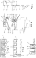
- Figure 1 Shows a perspective of the connector inserted to the tabs of the support of the lights indicating residual heat in the heaters, noticing the cavities to place the corresponding terminals of the conductor cables.
- Figure 2 Shows a perspective in lateral front elevation of the connector in the above figure, where there is a longitudinal section, with regard to one of the cavities or trakcs, to place the terminal of the corresponding conductor cable, noticing the lower base opened so that the tab to be connected can go through it.
- Figure 3 Shows a perspective of the connector of regulators/ switches, with the hinged cover opened, noticing the grooves to place the conductor cables.
- Figure 4 Shows a perspective in lateral front elevation, where are noticed the pivots to fit the cover to the support of the connector itself.
- Figure 5 Shows a view according to a section of the connector shown in Figure 3, through section A-A.
- the connector 1 that is inserted to the support of the lights indicating residual heat in the heaters of the vitroceramic plate is defined by a support supplied with the cavities 2 where are conventionally fitted the terminals of the ends of the conductor cables, which are related to the reductions 3 of one of the sides of the connector 1, in such a way that the tabs of the support of the lights indicating residual heat, are inserted through the lower part 4 of the connector 1 in order to make the connection.
- the connector 5 that is inserted to the regulators/switches of the device controls is defined by a support 13 supplied with the cavities 9 where are place the conventional terminals of the conductor cables, in such a way that the cavities or tracks 9 placed in relation to the perimeter of the support 13 have a reduction 10 through which the conductor cable appears, while the internal cavities or tracks 9 of the support 13, have a groove 11 through which the cable is conducted up to coming out of the support through its corresponding lateral reduction 12.
- the base of the support 13 through which the terminals of the conductor cables are fitted is closed by a cover 6 hinged to the support 13, supplied with some pivots 7 that fit into the respective holes 8 of the support 13, allowing the closing for its perfect isolation.
- the operator receives the conductor cables with the corresponding connectors, in such a way that he only has to couple the connectors 1 and 5 in the respective tabs, operation carried out quickly and with no possibility of error in the connection, which, means an important saving of time which, consequently, leads to an economing saving.
Landscapes
- Chemical & Material Sciences (AREA)
- Engineering & Computer Science (AREA)
- Ceramic Engineering (AREA)
- Details Of Connecting Devices For Male And Female Coupling (AREA)
- Cookers (AREA)
- Baking, Grill, Roasting (AREA)
- Resistance Heating (AREA)
- Multi-Conductor Connections (AREA)
Applications Claiming Priority (2)
| Application Number | Priority Date | Filing Date | Title |
|---|---|---|---|
| ES09300960A ES2070740B1 (es) | 1993-02-17 | 1993-02-17 | Sistema conector para aparatos de coccion. |
| ES9300960 | 1993-02-17 |
Publications (3)
| Publication Number | Publication Date |
|---|---|
| EP0619629A2 true EP0619629A2 (de) | 1994-10-12 |
| EP0619629A3 EP0619629A3 (de) | 1996-02-28 |
| EP0619629B1 EP0619629B1 (de) | 2000-09-06 |
Family
ID=8281708
Family Applications (1)
| Application Number | Title | Priority Date | Filing Date |
|---|---|---|---|
| EP94500024A Expired - Lifetime EP0619629B1 (de) | 1993-02-17 | 1994-02-11 | Verbindersystem für Kochplatten |
Country Status (3)
| Country | Link |
|---|---|
| EP (1) | EP0619629B1 (de) |
| DE (1) | DE69425771T2 (de) |
| ES (1) | ES2070740B1 (de) |
Cited By (2)
| Publication number | Priority date | Publication date | Assignee | Title |
|---|---|---|---|---|
| EP0860662A3 (de) * | 1997-02-19 | 2000-10-04 | BSH Balay, S.A. | Abdeckplatte für das elektrische System einer Kochplatte |
| WO2008108526A3 (en) * | 2007-03-08 | 2009-09-03 | Lg Electronics Inc. | Heating device |
Family Cites Families (5)
| Publication number | Priority date | Publication date | Assignee | Title |
|---|---|---|---|---|
| DE7814217U1 (de) * | 1978-05-11 | 1978-08-24 | Fischer, Karl, 7519 Oberderdingen | Kochmulde mit einer die kochflaeche bildenden glaskeramikplatte |
| DE3728528A1 (de) * | 1987-08-27 | 1989-03-09 | Ego Elektro Blanc & Fischer | Elektrokochplatten-anschlussstueck |
| DE8800513U1 (de) * | 1988-01-18 | 1989-05-18 | Siemens AG, 1000 Berlin und 8000 München | Verteilerdose mit mehreren Klemmanschlüssen |
| FR2627024B1 (fr) * | 1988-02-05 | 1990-07-13 | Seb Sa | Socle en matiere plastique pour recipient de cuisson electrique, procede de fixation du cable d'alimentation a ce socle et recipient pourvu d'un tel socle |
| DE9108462U1 (de) * | 1991-07-09 | 1991-08-29 | Pistor + Boss GmbH, 5880 Lüdenscheid | Vorrichtung zur Anzeige der Restwärme von Kochplatten |
-
1993
- 1993-02-17 ES ES09300960A patent/ES2070740B1/es not_active Expired - Fee Related
-
1994
- 1994-02-11 EP EP94500024A patent/EP0619629B1/de not_active Expired - Lifetime
- 1994-02-11 DE DE69425771T patent/DE69425771T2/de not_active Expired - Fee Related
Cited By (4)
| Publication number | Priority date | Publication date | Assignee | Title |
|---|---|---|---|---|
| EP0860662A3 (de) * | 1997-02-19 | 2000-10-04 | BSH Balay, S.A. | Abdeckplatte für das elektrische System einer Kochplatte |
| WO2008108526A3 (en) * | 2007-03-08 | 2009-09-03 | Lg Electronics Inc. | Heating device |
| KR101306725B1 (ko) * | 2007-03-08 | 2013-09-10 | 엘지전자 주식회사 | 히팅장치 |
| US8981267B2 (en) | 2007-03-08 | 2015-03-17 | Lg Electronics Inc. | Cooktop heating element with improved connection structure |
Also Published As
| Publication number | Publication date |
|---|---|
| DE69425771T2 (de) | 2001-01-04 |
| EP0619629A3 (de) | 1996-02-28 |
| ES2070740R (de) | 1996-11-01 |
| ES2070740B1 (es) | 1997-06-01 |
| DE69425771D1 (de) | 2000-10-12 |
| ES2070740A2 (es) | 1995-06-01 |
| EP0619629B1 (de) | 2000-09-06 |
Similar Documents
| Publication | Publication Date | Title |
|---|---|---|
| US4131805A (en) | Line power cord adaptor | |
| US4815496A (en) | Power feeder for solenoid valves | |
| US5741142A (en) | Ground bus coupling module | |
| US5493194A (en) | Control signal and power bus connector arrangement for a multi-axis motor control | |
| EP0582777B1 (de) | Motoranschlussblock, insbesondere für Elektromotoren | |
| US3800390A (en) | Apparatus for connecting conductors to terminals in a preloaded electrical connector | |
| WO1997041714A1 (de) | Modulares, baugruppenweise erweiterbares peripheriegerät mit selbstaufbauender elektrischer verbindung | |
| EP1400789B1 (de) | Elektrische Leistungs- und Kommunikationssignalverteilungseinheit, insbesondere für Köpfe von kombinatorischen Waagen | |
| US3950058A (en) | Programmable wiring system and junction box for use therein | |
| US5166491A (en) | Master computer controlled modular welder, weld control and power unit apparatus and method | |
| EP0619629A2 (de) | Verbindersystem für Kochplatten | |
| EP0817217A2 (de) | Gerät mit Sicherheitsvorrichtung | |
| US5961335A (en) | Decentralized input/output module for a data bus | |
| CA1144251A (en) | Bolted/welded joint for switchboard run-in connector | |
| JP2000509207A (ja) | 自己支持構造のモジュール拡張式モジュラー型周辺装置 | |
| FR2584873B1 (fr) | Systeme de raccordement electrique pour un reseau specifique de distribution de courant, et adaptateur pour fiche de raccordement electrique et socle de prise de courant correspondants | |
| DE69718717T2 (de) | Elektrisches Gerät | |
| ITPN20020015U1 (it) | Elettrodomestico con dispositivo perfezionato di inserimento del cavodi alimentazione. | |
| US5200885A (en) | Double burn-in board assembly | |
| EP0798835B1 (de) | Schalttafel und Anschlusseinrichtung für elektrische Installationen mit modularen Einrichtungen | |
| GB2048580A (en) | Testing terminal unit and plug | |
| EP0865119A3 (de) | Anschlussdose für ein Verteilernetz | |
| JP3077078B2 (ja) | 耐圧試験用短絡コネクタ | |
| US6167617B1 (en) | Method of blind connecting an I/O module into a cabinet | |
| JP2565594B2 (ja) | 機番設定方式 |
Legal Events
| Date | Code | Title | Description |
|---|---|---|---|
| PUAI | Public reference made under article 153(3) epc to a published international application that has entered the european phase |
Free format text: ORIGINAL CODE: 0009012 |
|
| AK | Designated contracting states |
Kind code of ref document: A2 Designated state(s): DE FR GB NL |
|
| PUAL | Search report despatched |
Free format text: ORIGINAL CODE: 0009013 |
|
| AK | Designated contracting states |
Kind code of ref document: A3 Designated state(s): DE FR GB NL |
|
| 17P | Request for examination filed |
Effective date: 19961029 |
|
| 17Q | First examination report despatched |
Effective date: 19981013 |
|
| GRAG | Despatch of communication of intention to grant |
Free format text: ORIGINAL CODE: EPIDOS AGRA |
|
| GRAG | Despatch of communication of intention to grant |
Free format text: ORIGINAL CODE: EPIDOS AGRA |
|
| GRAH | Despatch of communication of intention to grant a patent |
Free format text: ORIGINAL CODE: EPIDOS IGRA |
|
| RIC1 | Information provided on ipc code assigned before grant |
Free format text: 7H 01R 24/00 A, 7H 05B 3/74 B |
|
| GRAH | Despatch of communication of intention to grant a patent |
Free format text: ORIGINAL CODE: EPIDOS IGRA |
|
| RAP1 | Party data changed (applicant data changed or rights of an application transferred) |
Owner name: BSH BALAY, S.A. |
|
| GRAA | (expected) grant |
Free format text: ORIGINAL CODE: 0009210 |
|
| AK | Designated contracting states |
Kind code of ref document: B1 Designated state(s): DE FR GB NL |
|
| ET | Fr: translation filed | ||
| REF | Corresponds to: |
Ref document number: 69425771 Country of ref document: DE Date of ref document: 20001012 |
|
| PLBE | No opposition filed within time limit |
Free format text: ORIGINAL CODE: 0009261 |
|
| STAA | Information on the status of an ep patent application or granted ep patent |
Free format text: STATUS: NO OPPOSITION FILED WITHIN TIME LIMIT |
|
| 26N | No opposition filed | ||
| REG | Reference to a national code |
Ref country code: GB Ref legal event code: IF02 |
|
| PGFP | Annual fee paid to national office [announced via postgrant information from national office to epo] |
Ref country code: GB Payment date: 20040202 Year of fee payment: 11 |
|
| PGFP | Annual fee paid to national office [announced via postgrant information from national office to epo] |
Ref country code: FR Payment date: 20040218 Year of fee payment: 11 |
|
| PGFP | Annual fee paid to national office [announced via postgrant information from national office to epo] |
Ref country code: NL Payment date: 20040223 Year of fee payment: 11 |
|
| PGFP | Annual fee paid to national office [announced via postgrant information from national office to epo] |
Ref country code: DE Payment date: 20040302 Year of fee payment: 11 |
|
| PG25 | Lapsed in a contracting state [announced via postgrant information from national office to epo] |
Ref country code: GB Free format text: LAPSE BECAUSE OF NON-PAYMENT OF DUE FEES Effective date: 20050211 |
|
| PG25 | Lapsed in a contracting state [announced via postgrant information from national office to epo] |
Ref country code: NL Free format text: LAPSE BECAUSE OF NON-PAYMENT OF DUE FEES Effective date: 20050901 Ref country code: DE Free format text: LAPSE BECAUSE OF NON-PAYMENT OF DUE FEES Effective date: 20050901 |
|
| GBPC | Gb: european patent ceased through non-payment of renewal fee |
Effective date: 20050211 |
|
| PG25 | Lapsed in a contracting state [announced via postgrant information from national office to epo] |
Ref country code: FR Free format text: LAPSE BECAUSE OF NON-PAYMENT OF DUE FEES Effective date: 20051031 |
|
| NLV4 | Nl: lapsed or anulled due to non-payment of the annual fee |
Effective date: 20050901 |
|
| REG | Reference to a national code |
Ref country code: FR Ref legal event code: ST Effective date: 20051031 |