EP0619640A2 - Moteur à réluctance variable - Google Patents
Moteur à réluctance variable Download PDFInfo
- Publication number
- EP0619640A2 EP0619640A2 EP94105387A EP94105387A EP0619640A2 EP 0619640 A2 EP0619640 A2 EP 0619640A2 EP 94105387 A EP94105387 A EP 94105387A EP 94105387 A EP94105387 A EP 94105387A EP 0619640 A2 EP0619640 A2 EP 0619640A2
- Authority
- EP
- European Patent Office
- Prior art keywords
- reluctance motor
- poles
- inductance
- period
- section
- Prior art date
- Legal status (The legal status is an assumption and is not a legal conclusion. Google has not performed a legal analysis and makes no representation as to the accuracy of the status listed.)
- Ceased
Links
Images


Classifications
-
- H—ELECTRICITY
- H02—GENERATION; CONVERSION OR DISTRIBUTION OF ELECTRIC POWER
- H02K—DYNAMO-ELECTRIC MACHINES
- H02K41/00—Propulsion systems in which a rigid body is moved along a path due to dynamo-electric interaction between the body and a magnetic field travelling along the path
- H02K41/02—Linear motors; Sectional motors
- H02K41/03—Synchronous motors; Motors moving step by step; Reluctance motors
-
- H—ELECTRICITY
- H02—GENERATION; CONVERSION OR DISTRIBUTION OF ELECTRIC POWER
- H02K—DYNAMO-ELECTRIC MACHINES
- H02K19/00—Synchronous motors or generators
- H02K19/02—Synchronous motors
- H02K19/10—Synchronous motors for multi-phase current
- H02K19/103—Motors having windings on the stator and a variable reluctance soft-iron rotor without windings
Definitions
- the invention relates to a reluctance motor, consisting of a stationary element and a second, movable element, both of which have a number of poles, the poles of an element being switched on and off by an electrical current I flowing through the excitation coils assigned to the poles in a predetermined order
- Time-limited sections can be magnetized and a magnetic circuit is generated between adjacent poles of the stationary element and the movable element, which tries to align adjacent poles of the two elements in the pursuit of minimum magnetic resistance or maximum inductance L and thereby converts supplied electrical energy into kinetic energy .
- the simplest reluctance motor consists of an electromagnet and an iron core, which are movable relative to each other. If an electric current I flows through the coil of the inductance L of the electromagnet, then the electromagnet and iron core form a closed magnetic circuit and a force F acts between the electromagnet and the iron core, which causes a displacement d s and generates the mechanical energy F ⁇ d s . The relative movement changes the magnetic resistance of the magnetic circuit and thus the inductance L of the coil, which is responsible for the magnetic flux.
- the force between the electromagnet and the iron core, which aims to align both bodies, is At a constant current I, the force F is constant when the inductance L increases linearly with the distance ds covered.
- the reluctance motor does mechanical work, it absorbs electrical energy. If I is constant, the absorbed electrical energy 2 ⁇ ⁇ L each converted half into mechanical (useful) energy and reversibly into energy stored in the magnetic field.
- a continuously operating drive system must therefore consist of at least two periodically activatable subsystems (phases), the periods of which essentially have two sections.
- phases the periods of which essentially have two sections.
- electrical energy is supplied and converted into mechanical energy (movement) and magnetic energy (reversible in Magnetic field stored) converted, in order to generate a constant force, the inductance L must increase linearly: dL / ds> 0.
- the magnetic energy coupled with the current I is converted back into electrical energy. If the motor is also to run in the opposite direction, then for symmetry reasons it applies that the inductance L decreases linearly at the beginning of the second section. dL / ds ⁇ 0.
- the course of the inductance L thus follows a triangular function; this course applies to both subsystems, the period of the first subsystem being out of phase by 1/2 period.
- the disadvantages of the two-phase system are that no targeted directional control is possible because the derivation of the inductance function at the reversal point is not continuous, and that after the reversal point in which the inductance L is at a maximum, the current cannot be jumped back to zero . Since the slope of the inductance function in this section is negative (dL / ds ⁇ 0), there is a braking force and the system functions as a generator, with some of the mechanical energy generated being converted back into electrical energy. The smoothness of the engine suffers.
- the change in inductance L of a phase is a function of the angle of rotation of a rotary motor in an idealized form.
- the inductance L shows a course which is very unfavorable for a continuous movement. Because of the inductance curve shown, it cannot be avoided that after the reversal point has been exceeded, a braking torque occurs during the drop from L max to L min , which significantly impairs the smooth running of the motor.
- the invention is therefore based on the object of optimizing the periodic course of excitation current I and inductance L and of coordinating the geometric arrangement and design of the poles of the stationary element and of the movable element of the reluctance motor and of executing them in such a way that they run very smoothly, ie constant Power effect is achieved and also an economical production of such motors is guaranteed.
- This object is achieved in that the geometric arrangement and design of the poles of the stationary element and the movable element of the reluctance motor and the periodic course of excitation current I and inductance L of a phase during the movement of the reluctance motor are so coordinated that in the first section the period the inductance L is constant and minimum L min and the excitation current I increases from zero to the setpoint I soll , that in the second section of the period the inductance L increases linearly from the minimum value L min to the maximum value L max with constant excitation current I soll that in the third section of the period the inductance L maintains the maximum value L max and the excitation current I drops to zero, and that in the fourth section of the period the inductance L decreases from the maximum value L max to the initial value L min and the excitation current I is zero .
- the first section takes 1/12 of the period, the second section 1/3 of the period, the third section 1/4 of the period and the fourth section 1/3 of the period be.
- each pole of the movable element is provided with excitation coils, the pole being in the form of a hexagon wound from sheet metal, the opposite tips of which are cut off to form two halves which can be wound separately, and in that the side surfaces of the poles formed by the end faces of the sheets have trapezoidal incisions extending from the pole surfaces and running inwards.
- the magnetic circuit is oriented perpendicular to the direction of movement of the movable element.
- the invention provides that the orientation of the laminated sheets of the stationary element and the movable element is crossed.
- a reluctance motor which generates a continuously and constantly acting force and thus has a high level of smoothness, and which, due to the geometrical design of the poles and the orientation of the magnetic field lines, is simple to construct and economical to produce is.
- the embodiment of the reluctance motor according to the invention enables long-range transport systems to be implemented, and because of the very large force at low speeds, the motor is advantageously used as a generator for slow-running drives (wind generator without gear).
- the electrical reluctance motor is known both as a rotary and a linear motor and is used equally. It is common to both motors that they consist of a stationary element, hereinafter referred to as the stator, and of a movable element, both of which are equipped with a series of poles.
- the stator In the rotary motor, the stator is designed as a circular ring, in the interior of which the movable element executes rotary movements and is accordingly referred to as a rotor.
- the stator is elongated and the movable element, hereinafter referred to as the actuator, performs linear movements within the stator.
- FIG. 1 shows a schematic illustration of a side view of a linear reluctance motor denoted by 1, the stator 2 of which has comb-like projecting poles 4 which are fastened on corresponding supports 2a, 2b with any magnetic properties, for example concrete, plastic or similar materials.
- the actuator 3 Arranged between the stator poles 4 is the actuator 3 which is movable in the direction of the arrow and which, in the three-phase reluctance motor 1 shown as an exemplary embodiment, consists of three interconnected actuator poles 5.
- the actuator poles 5 are provided with excitation coils 6 and not, as is customary, the stator poles 4. This embodiment proves to be the case with elongated linear motors 1, i.e.
- the electrical energy supplied is concentrated on three actuator poles 5, which results in a higher current density and can lead to undesired heating;
- the excitation current I must be supplied to the excitation coils 6 of the movable actuator poles 5 via known connection elements, which are not shown in the drawing.
- the magnetic circuit of the reluctance motor 1 consists of the series connection of a low magnetic resistance with a constant value, which is generated by the core of the excitation coil 6 and the stator pole 4, and a high magnetic resistance with a periodically variable value, which is created by the air gap 8 between the stator pole 4 and moving actuator pole 5 is generated.
- the invention provides to design the magnetic circuit so that the magnetic resistance and thus the inversely proportional inductance L of a phase can be changed periodically so that it is constant and minimal L at the beginning of the period min , then increases linearly from the minimum value L min to the maximum value L max , then remains constant and finally decreases again to the minimum output value L min , the course of the excitation current I being matched to the course of the inductance L.
- a phase generates a force only during 1/3 of its period.
- a continuously and constantly acting force is generated during the entire period, without braking effects due to non-coordinated inductance and excitation current profiles impairing the smooth running of the reluctance motor 1.
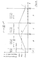
- 3a to 3d schematically show the course of the movement of an actuator pole 5 within the stator poles 4 during a period and the corresponding location-dependent profile of the inductance L.
- the starting position of the actuator pole 5 is identified by the solid rectangle, the end position of the actuator pole 5 by the dashed rectangle and the direction of movement by the arrow.
- the actuator pole 5 moves, for example, with its right edge from the left into the area of two opposite stator poles 4 until the right edges of the actuator pole 5 and opposite stator poles 4 are in alignment; the inductance L increases linearly from L min to L max .
- the actuator pole 5 moves further to the right within the area of opposite stator poles 4 until its left edge is aligned with the left edges of the stator poles 4; the inductance remains constant and is a maximum of L max .
- section D the actuator pole 5 moves out of the area of the opposite stator poles 4 and returns to its starting position according to FIG. 3a; the inductance L decreases linearly from L max to L min .
- a reluctance motor that shows this behavior is the linear motor 1 shown in FIG. 1 with the stator and actuator poles 4, 5 designed and arranged according to the invention.
- the width x 1 of the pole face 9 of a stator pole 4 is related to the distance x 2 of two adjacent stator poles 4 like 1: 2.
- the design of the poles 4, 5 is also of crucial importance for the quality of the reluctance motor 1.
- magnetically conductive materials for example iron, ferrites or amorphous materials for the magnetic and copper for the electrical circuit. These materials are not ideal. Copper has an ohmic resistance and converts electrical energy into heat.
- the magnetically conductive materials whether hard or soft, cannot be magnetized to any degree and also generate heat when remagnetized.
- the cores of the stator and actuator poles 4, 5 can be made of mutually insulated, mutually bonded sheets of magnetically conductive materials, usually iron, be composed.
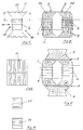
- the structure of such an actuator pole 5 according to the invention is shown in FIGS. 4 to 8 in different views.
- the invention provides for the geometry of the actuator pole 5 to approximate the circular shape, as a result of which a smaller magnetic field length can be achieved compared to the conventional rectangular shape.
- the circular shape can be adjusted with good approximation if, as can be seen from the front view of an actuator pole in FIG. 4, the core of the actuator pole 5 emerges from a hexagon wound from a strip-shaped sheet metal, the opposite tips of the hexagon being cut off.
- the two halves 5a, 5b formed are wound separately in the central part, so that two electromagnets are formed, the adjacent poles of which are a north and a south pole N, S (FIG. 8).
- the core of the pole 5 has a trapezoidal cut 11 on both sides formed by the end faces of the metal sheets 7.
- this creates the required winding space for the excitation coil 6 and, on the other hand, the cross-sectional area of the core is made square in the area of the surrounding winding, as the sectional illustration in FIG. 7 shows.
- the resulting advantages are that the actuator poles 3 of the three phases can be mounted very close to each other, which leads to a short construction of the entire actuator 3 and in the linear motor 1 to a larger stroke and that the winding length is minimal due to the square cross section .
- the L gradient d L / d s determines the force of the motor. It is state of the art to multiply d L / d s by forming teeth on the poles, the achievable speed decreasing but the power remaining constant.
- the pole faces 9 are toothed and the sheets 7 of the stator poles 4 are made thinner.
- the pole toothing 10 extends perpendicular to the direction of movement of the actuator pole, which is indicated by an arrow in FIG. 5, from one end of the pole 5 to the other end.
- the pole toothing is designed such that the width of the pole teeth relates to the width of the interdental spaces such as 7/12: 5/12, which is not clearly evident from FIGS. 5 and 6.
- the magnetic circuit which can be seen from the course of the magnetic field lines with the actuator and stator poles 4, 5 aligned in FIG. 8, is not oriented in the direction of movement of the actuator 3 as is usual, but perpendicular to it.
- the stator 2 no longer consists of long toothed metal sheets 7, as before, but that the stator poles 4 can be assembled from simple sheet metal pieces. This makes it very cheap to manufacture, and even pieces of waste can be used to produce transformer cores.
- the inventive design of the stator 2 and the stator poles 4 allows that the stator 2 can be bent to a limited extent and transport systems are possible over larger distances. In addition, the space between the stator poles 4 is free and gives a good possibility of cooling.
Landscapes
- Engineering & Computer Science (AREA)
- Power Engineering (AREA)
- Physics & Mathematics (AREA)
- Chemical & Material Sciences (AREA)
- Combustion & Propulsion (AREA)
- Electromagnetism (AREA)
- Synchronous Machinery (AREA)
- Linear Motors (AREA)
Applications Claiming Priority (2)
| Application Number | Priority Date | Filing Date | Title |
|---|---|---|---|
| DE4311664 | 1993-04-08 | ||
| DE19934311664 DE4311664A1 (de) | 1993-04-08 | 1993-04-08 | Reluktanzmotor |
Publications (2)
| Publication Number | Publication Date |
|---|---|
| EP0619640A2 true EP0619640A2 (fr) | 1994-10-12 |
| EP0619640A3 EP0619640A3 (fr) | 1995-08-16 |
Family
ID=6485111
Family Applications (1)
| Application Number | Title | Priority Date | Filing Date |
|---|---|---|---|
| EP94105387A Ceased EP0619640A3 (fr) | 1993-04-08 | 1994-04-07 | Moteur à réluctance variable. |
Country Status (2)
| Country | Link |
|---|---|
| EP (1) | EP0619640A3 (fr) |
| DE (1) | DE4311664A1 (fr) |
Families Citing this family (4)
| Publication number | Priority date | Publication date | Assignee | Title |
|---|---|---|---|---|
| DE19604645A1 (de) * | 1996-02-08 | 1997-08-14 | Stemme Otto | Elektroantrieb |
| DE19846872B4 (de) * | 1998-10-12 | 2006-06-08 | Sew-Eurodrive Gmbh & Co. Kg | Linearer geschalteter Reluktanzmotor und Verfahren zum Betreiben eines linearen geschalteten Reluktanzmotors |
| DE102017127021A1 (de) | 2017-11-16 | 2019-05-16 | Technische Universität Wien | Reluktanz-Linearaktor und damit ausgeführte Werkzeuge/Antriebe |
| DE102022117759A1 (de) | 2022-07-15 | 2024-01-18 | Technische Universität Wien | Linearaktor mit optimierter Induktivität und Verfahren zum Wickeln und Verschalten von Spulen |
Family Cites Families (8)
| Publication number | Priority date | Publication date | Assignee | Title |
|---|---|---|---|---|
| GB1561032A (en) * | 1976-06-10 | 1980-02-13 | Workman J | Laminated foil stator |
| GB1591346A (en) * | 1977-03-30 | 1981-06-17 | Chloride Group Ltd | Reluctance electric motor drive systems |
| US4149808A (en) * | 1977-09-14 | 1979-04-17 | Exxon Research & Engineering Co. | Linear drive for a printing apparatus |
| FR2510838A1 (fr) * | 1981-07-28 | 1983-02-04 | Od Polt Institut | Moteur electrique lineaire a deux coordonnees |
| GB2105536B (en) * | 1981-09-08 | 1985-09-18 | Chloride Group Ltd | A multi-phase switched variable-reluctance motor |
| FR2544926B1 (fr) * | 1983-04-20 | 1986-05-30 | Jarret Jacques | Anneau magnetique pour generateurs rectilignes a pistons libres |
| GB8816713D0 (en) * | 1988-07-14 | 1988-08-17 | Univ Court Of University Of Gl | Motor drive system |
| US5015903A (en) * | 1988-08-15 | 1991-05-14 | Pacific Scientific Company | Electronically commutated reluctance motor |
-
1993
- 1993-04-08 DE DE19934311664 patent/DE4311664A1/de not_active Ceased
-
1994
- 1994-04-07 EP EP94105387A patent/EP0619640A3/fr not_active Ceased
Also Published As
| Publication number | Publication date |
|---|---|
| DE4311664A1 (de) | 1994-10-13 |
| EP0619640A3 (fr) | 1995-08-16 |
Similar Documents
| Publication | Publication Date | Title |
|---|---|---|
| DE69214812T2 (de) | Elektrische maschinen | |
| EP0762619B1 (fr) | Méthode et dispositif pour réduire la pulsation du couple dans un moteur électrique | |
| DE69121583T2 (de) | Kommutierter mehrphasenreluktanzmotor | |
| DE69406706T2 (de) | Hybriderregungstype eines Permanentmagnet-Synchronmotors | |
| EP1064712B1 (fr) | Moteur a flux transversal polyphase | |
| DE69113482T2 (de) | Elektrischer motor. | |
| EP3545610B1 (fr) | Machine synchrone à démultiplication magnétique de champ tournant et concentration de flux | |
| WO1999001924A1 (fr) | Machine electrique a dents magnetiques douces et son procede de fabrication | |
| EP1314236B1 (fr) | Machine electrique pour frequences de demagnetisation elevees | |
| DE102012212637A1 (de) | Gießtechnisch hergestellte elektrische Spule | |
| DE2515133B2 (de) | Reluktanzmaschinenanordnung | |
| DE10220822B4 (de) | Linearmotor | |
| DE2623234B2 (fr) | ||
| EP2605367A1 (fr) | Machine à flux transversal dotée de structures de Halbach | |
| DE2030789C3 (de) | Reluktanzmaschine | |
| DE68910181T2 (de) | Elektrische Maschinen. | |
| DE102009057446B4 (de) | Elektrische Maschine | |
| DE60125194T2 (de) | Wanderfeld Synchronmotor | |
| DE3401163C2 (de) | Elektrische Maschine oder magnetische Tragvorrichtung | |
| DE4306727A1 (de) | Einphasiger Reluktanzmotor zum Starten dieses Motors in einer gewünschten Drehrichtung | |
| EP0619640A2 (fr) | Moteur à réluctance variable | |
| EP0134827A1 (fr) | Entraînement électromagnétique pour mouvements linéaires ou rotatifs continus et pas à pas | |
| WO2014071960A1 (fr) | Moteur électrique présentant une inductance améliorée, et procédé d'enroulement et de connexion de bobines | |
| DD224725A1 (de) | Schrittmotor | |
| DE4302807C2 (de) | Mehrphasige elektrische Maschine und Verfahren zu ihrer Herstellung |
Legal Events
| Date | Code | Title | Description |
|---|---|---|---|
| PUAI | Public reference made under article 153(3) epc to a published international application that has entered the european phase |
Free format text: ORIGINAL CODE: 0009012 |
|
| AK | Designated contracting states |
Kind code of ref document: A2 Designated state(s): AT BE CH DE DK ES FR GB IE IT LI NL PT SE |
|
| PUAL | Search report despatched |
Free format text: ORIGINAL CODE: 0009013 |
|
| AK | Designated contracting states |
Kind code of ref document: A3 Designated state(s): AT BE CH DE DK ES FR GB IE IT LI NL PT SE |
|
| 17P | Request for examination filed |
Effective date: 19960213 |
|
| 17Q | First examination report despatched |
Effective date: 19960326 |
|
| STAA | Information on the status of an ep patent application or granted ep patent |
Free format text: STATUS: THE APPLICATION HAS BEEN REFUSED |
|
| 18R | Application refused |
Effective date: 19980108 |