EP0619963A1 - Instrument zur Erlangung der Schönheit - Google Patents
Instrument zur Erlangung der Schönheit Download PDFInfo
- Publication number
- EP0619963A1 EP0619963A1 EP93202847A EP93202847A EP0619963A1 EP 0619963 A1 EP0619963 A1 EP 0619963A1 EP 93202847 A EP93202847 A EP 93202847A EP 93202847 A EP93202847 A EP 93202847A EP 0619963 A1 EP0619963 A1 EP 0619963A1
- Authority
- EP
- European Patent Office
- Prior art keywords
- opening portion
- electromagnet
- unit according
- beauty unit
- pressing
- Prior art date
- Legal status (The legal status is an assumption and is not a legal conclusion. Google has not performed a legal analysis and makes no representation as to the accuracy of the status listed.)
- Withdrawn
Links
Images



Classifications
-
- A—HUMAN NECESSITIES
- A45—HAND OR TRAVELLING ARTICLES
- A45D—HAIRDRESSING OR SHAVING EQUIPMENT; EQUIPMENT FOR COSMETICS OR COSMETIC TREATMENTS, e.g. FOR MANICURING OR PEDICURING
- A45D44/00—Other cosmetic or toiletry articles, e.g. for hairdressers' rooms
-
- A—HUMAN NECESSITIES
- A61—MEDICAL OR VETERINARY SCIENCE; HYGIENE
- A61H—PHYSICAL THERAPY APPARATUS, e.g. DEVICES FOR LOCATING OR STIMULATING REFLEX POINTS IN THE BODY; ARTIFICIAL RESPIRATION; MASSAGE; BATHING DEVICES FOR SPECIAL THERAPEUTIC OR HYGIENIC PURPOSES OR SPECIFIC PARTS OF THE BODY
- A61H9/00—Pneumatic or hydraulic massage
- A61H9/005—Pneumatic massage
-
- A—HUMAN NECESSITIES
- A61—MEDICAL OR VETERINARY SCIENCE; HYGIENE
- A61H—PHYSICAL THERAPY APPARATUS, e.g. DEVICES FOR LOCATING OR STIMULATING REFLEX POINTS IN THE BODY; ARTIFICIAL RESPIRATION; MASSAGE; BATHING DEVICES FOR SPECIAL THERAPEUTIC OR HYGIENIC PURPOSES OR SPECIFIC PARTS OF THE BODY
- A61H9/00—Pneumatic or hydraulic massage
- A61H9/005—Pneumatic massage
- A61H9/0071—Pneumatic massage by localized pressure, e.g. air streams or jets
Definitions
- the present invention relates to a beauty unit for applying an absorbing action and a pressing action to the skin.
- a conventional beauty unit in which an absorbing action and a pressing action are applied to the skin so as to rise stains, makeup dregs or the like adhered to a sweat gland and a sebaceous gland to the skin surface or a massage is given to the skin so as to facilitate the circulation of the blood.
- a beauty unit as described has a body capable of being carried by hand.
- the body is interiorly provided with a motor, a motion conversion mechanism for converting rotation of the motor into reciprocating motion, and an operating body in which a diaphragm is operated by the motion conversion mechanism to alternately form a negative pressure state and a pressing state.
- a skin contact portion is provided on the outside of the body. This skin contact portion is brought into pressure contact with the skin surface to thereby apply the absorbing action and the pressing action to the skin surface.
- An object of the present invention is to improve the above-described disadvantages of the prior art and to provide a beauty unit whose portion carried by hand is light in weight and manipulatability is excellent.
- a beauty unit comprises an electromagnet excited by a commercial power supply, an air pump having an absorbing opening portion for guiding negative pressure air and a discharge opening portion for guiding a pressing opening portion wherein a negative pressure state and a pressing state are alternately formed in an internal chamber by amplitude motion of diaphragms, operating members associated with the exciting action of the electromagnet to apply the amplitude motion to the diaphragms of the air pump, a control circuit for controlling the exciting action of the electromagnet, a body having inserting opening portions connected to the absorbing opening portion and the discharge opening portion, respectively, and an manipulating member comprising a flexible tube having a rear end connector capable of being inserted into the inserting opening portion provided at one end and a skin contact appliance provided at the other end.
- the air pump is formed at both left and right sides with diaphragms for receiving external vibrations from the center portion to provide amplitude, and further formed at both left and right sides with operating members, which are in turn connected to the center portions of the diaphragms.
- the control circuit comprises a frequency switching circuit having a terminal for continuously outputting commertial frequencies to the electromagnet and a terminal for intermittently outputting commertial frequencies, an output switching circuit for switching the magnitude of output of a commercial power supply, a light emitting element to be lighted when a power supply is inputted, and a light emitting element to be lighted when the output of the frequency switching circuit is turned ON.
- the body comprises a square bottom plate and a cover for covering the upper portion of the bottom plate.
- the electromagnet, the air pump, the operating members, the control circuit are arranged on the bottom plate. These parts are covered with the cover, and the inserting opening portion is exposed to a part of the cover, A switching rotatable knob for the frequency switching circuit and a switching pressing portion for the output switching circuit in the control circuit are projected through a hole provided in the cover.
- the light emitting elements are provided opposite to a transparent plate provided on the body.
- a front connector is provided at the front end of the introducing tube, and the connector is removably closely fitted in a hollow shaft portion of the skin contact appliance provided integral with the bowl-like contact portion at the extreme end of the hollow shaft portion.
- a front connector is provided at the front end of the introducing pipe, and the connector is removably closely fitted in the hollow shaft portion of the skin contact appliance comprising an instrument having a diaphragm which provides amplitude by vibration of air and a pressing element which is vibrated by the amplitude of the diaphragm at the extreme end of the hollow shaft portion.
- the front connector has in its outer periphery a recessed groove extending from an intermediate position to the foremost edge in the lengthwise direction thereof, and the skin contact appliance has in its inner periphery of the shaft portion a recessed groove extending from an intermediate position to the end edge in the lengthwise direction.
- the control circuit when a commercial power supply is applied by a power supply cord, the control circuit is operated so that N-pole and S-pole of the electromagnet are alternately magnetized.
- the diaphragms provide the amplitude by the operating members which are vibrated in response to the exciting action, and thus the negative pressure state and the pressing state are alternately formed in the internal chamber of the air pump.
- the negative pressure air generated by the negative pressure state is introduced into the absorption opening portion, and the pressing air generated by the pressing state is introduced into the discharge opening portion.
- the electromagnet When the frequency switching circuit is switched, the electromagnet is continuously or intermittently excited, and when the output switching circuit is switched, the magnitude of the magnetizing force is adjusted.
- the exciting state of the electromagnet is displayed by the light emitting element.
- the rear end connector of the operating appliance is connected to the inserting opening portion in communication with the absorption opening portion or the discharge opening portion, and the skin contact appliance is pressed against the skin. Then, when the rear end connector is connected to the absorption opening portion, it is possible to apply the absorption action to the skin. When the rear end connector is connected to the discharge opening portion, it is possible to apply the pressing action to the skin. Further, when a skin contact appliance provided with a pressing element is used, it is possibly to give the skin a massage.
- the unit can be used without occurrence of fatigue, and the manipulatability of the unit is excellent. Further it is possible to further add a large capacity electromagnet, an air pump and accessorial parts to the main body portion. Moreover, since the electromaget can be excited continuously or intermittently or the magnitude of the exciting action can be controlled, the unit can be applied to many modes of use. Furthermore, there is a further advantage that the intermittent pressing action and absorbing action can be positively carried out.
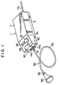
- the main body 1 comprises a shallow square bottom plate 2 having a rising rib along the peripheral edge and a deep box-like cover 3 whose lower surface is open and front portion is inclined frontwardly.
- the bottom plate 2 and the cover 3 are fastened by screws in the state where they are vertically joined together.
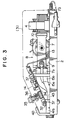
- the bottom plate 2 is provided with an electromagnet 4, a closed tubular air pump 8 whose both sides are closed by diaphragmes 6 and 6 and which alternately forms a negative pressure state and a pressing state in an internal chamber by applying amplitude motion to center portions of the diaphragms 6 and 6 and having an absorption opening portion 7a for introducing a negative pressure air and a discharge opening portion 7b for introducing a pressing air, a pair of operating members 12 and 13 having a base end 9 fixedly mounted on the air pump 8 opposite to left and right positons of the air pump 8 and having a magnet 10 opposite to the magnetizing surface of the electromagnet 4 at the free end thereof, a control circuit 14 for controlling the exciting of the electromagnet 4, and connecting tubes 15a and 15b connected to the absorption opening portion 7a and the discharge opening portion 7b, respectively.
- Boss portions 11 provided in the center portions of the diaphragms 6 and 6 forming the side of the air pump 8 are connected in the intermediate position to the pair of left and right operating members 12 and 13, respectively.
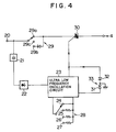
- a ultralow frequency oscillation circuit 23 comprised of IC is connected to an input terminal 20 of a commercial power supply through a series circuit of a voltage dropping capacitor 21 and a rectification circuit 22.
- a frequency switching circuit 28 Connected to the ultralow frequency oscillation circuit 23 is a frequency switching circuit 28 having a terminal 24 for continuously outputting the frequency and terminals 25, 26 and 27 for intermittently outputting the frequency at intervals of 0.08 second, 0.28 seconds and 1.2 seconds.
- a TRIAC SSR Solid State Relay
- the gate of the TRIAC SSR 30 is connected to the output end of the ultralow frequency oscillation circuit 23.
- a display circuit 33 comprising a light emitting element 31 of green, for example, which is lighted when a power supply is inputted and a light emitting element 32 of red, for example, which is lighted when the gate output is ON is connected to the frequency switching circuit 28.
- control circuit 14 is disposed on a printed board 34 and is provided with a rotatable knob 35 for switching the frequency switching circuit 28 and a push botton 36 which is tiltable in a see-saw manner for switching the output switching circuit 29.
- the printed board 34 is mounted in a frontwrdly inclined state by four corner portions thereof securely attached to four supports 37 stood upright on the bottom plate 2.
- the rotatable knob 35 and the push button 36 are projected so that they can be operated externally through a through-hole 38 provided in the inclined front surface portion 3a of the cover 3 when the cover 3 is securely attached to the bottom plate 2.
- a transparent plate 40 On the front central portion of the bottom plate 2 is stood upright a transparent plate 40, at the lower portion of which inserting opening portions 41a and 41b connected to the connecting tubes 15a and 15b, respectively, are arranged in parallel, the upper portion thereof being inwardly curved.
- This transparent plate 40 is fitted in a cut recess portion 42 provided in the front central portion of the cover 3 when the latter is mounted on the bottom plate 2.
- the light emitting elements 31 and 32 are positioned opposedly of the curved portion of the transparent plate 40.
- a filter 43 is interposed interiorly of the inserting opening portions 41a and 41b.
- an operating appliance 50 for applying an absorbing action and a pressing action to the skin comprises a lengthy flexible introducing tube 53 formed of synthetic resin provided at the rear end with a front connector 51 with a flange which can be selectively inserted into the inserting opening portions 41a and 41b and at the front end with a front connector 52 with a flange which can be inserted into skin contact appliances 56 and 67 which will be described later; a skin contct appliance 56 formed of synthetic resin in the form of a funnel as a whole in which a contact portion 55 is integrally provided at the extreme end of a hollow shaft portion 54 having the front connector 52 closely fitted therein as shown in Figs.
- said skin contact appliance 56 comprising a hemispherical cap 61 integrally provided at the extreme end of a hollow shaft portion 60 having the front connector 52 closely fitted therein and a lid plate 63 for closing the open surface of the cap 61 and having a diaphragm 62 fixedly fitted therein as shown in Figs. 7 and 8; and the skin contact appliance 67 having a warhead-like pressing portion 65 projected from a fitting hole 66 bored in the center portion of the lid plate 63 through a shaft 64 provided in the center portion of the diaphragm 62 so that the diaphragm 62 is subjected to amplitude by the entry of pressurized air to provide the pressing portion 65 amplitude.
- the front connector 52 comprises a tubular body having a flange 68 in the middle thereof.
- An axially extending engaging protrusion 69 is provided close to the flange 68 of an outer half portion 52a of the front connector 52, and a recessed groove 70 extending from an axial intermediate position to an outer end edge is provided at a position displaced by 90° therefrom.
- Two engaging grooves 71a and 71b selectively engaged with the engaging protrusion 69 are provided in the inner peripheral surfaces of the shaft portions 54 and 60 into which the front connector 52 is closely fitted diametrically opposing to a position of the opening portion thereof, and a recessed groove 72 is provided positioned in the middle therebetween, said recessed groove 72 extending from the lengthwise intermediate position to the end edge so that when the engaging protrusion 69 is engaged with one engaging groove 71a, the recessed groove 72 comes into communication with the recessed groove 70.
- the rotatable knob 35 is operated to be rotated to select, for example, the terminal 24 for continuation of the frequency switching circuit 28, the ON signal is continuously outputted from the ultralow frequency oscillation circuit 23. Accordingly, the electromagnet 4 is alternately excited to N-pole and S-pole at a period of 50/60 HZ to repeat the absorption action and repulsion action between the electromagnet 4 and the magnet 10 whereby the operating members 12 and 13 are vibrated. With this vibration, the center portions of the diaphragms 6 and 6 which constitute the sides of the air pump 8 provide amplitude in the direction of face.
- the internal chamber of the air pump 8 repeatedly assumes the negative pressure state and the pressing state, and when the internal chamber assumes the negative pressure state, the negative pressure air is guided into the absorption opening portion 7a.
- the pressurized air is guided into the discharge opening portion 7b, and the gate signal of the TRIAC SSR 30 is turned ON so that the red light emitting diode 32 is lighted to display the operating state.
- the exciting action of the magnet 4 is controlled at a period of 1.2 seconds, for example.
- the strong (high) and weak (low) states of air pressure can be selected by depressing the push button 36, and the continuous operation and intermittent operation can be selected by rotating the rotatable knob 35.
- the front connector 52 of the introducing tube 53 is connected to the shaft portion 54 and the rear connector 51 is connected to one of the inserting opening portions 41a and 41b provided on the main body 1.
- the contact portion 55 is then brought into pressure contact with the skin surface.
- the pressing action can be applied continuously or intermittently to the skin surface.
- the absorbing action can be applied continuously or intermittently to the skin surface to thereby enable rising stains, makeup dregs or the like adhered to a sweat gland and a sebaceous gland to the skin surface and giving a stimulus to the skin so as to facilitate the circulation of the blood.
- the front connector 52 of the introducing tube 53 is connected to the shaft portion 60 and the rear connector 51 thereof is connected to the inserting opening portion 41a or 41b provided on the main body 1.
- the pressing portion 65 is urged against the skin surface.
- the rotatable knob 35 is rotated to select the terminals 25 to 27 for intermittence.
- the diaphragm 62 is subjected to amplitude intermittently by the vibration of air, and therefore, the pressing portion 6 is also intermittently vibrated to enable giving a massage to the skin.
- the recessed grooves 70 and 72 are closed each other by the inner peripheral surface of the other so that the suction force and the pressing force within the contact portion 55 or the vibration pressure of the pressing portion can be increased.
- the imaginary line in Fig. 6 when the engaging protrusion 69 is engaged with the other engaging groove 71a, the recessed grooves 70 and 72 become communicated. Therefore, when the interior of the skin contact appliances 56 and 67 is changed from the pressing state to the stopping state, the pressure in the skin contact appliances 56 and 67 temporarily restores to the atmospheric pressure. Accordingly, this action is repeatedly carried out so that the intermittent pressing action and absorbing action are positively carried out.
Landscapes
- Health & Medical Sciences (AREA)
- Epidemiology (AREA)
- Pain & Pain Management (AREA)
- Physical Education & Sports Medicine (AREA)
- Rehabilitation Therapy (AREA)
- Life Sciences & Earth Sciences (AREA)
- Animal Behavior & Ethology (AREA)
- General Health & Medical Sciences (AREA)
- Public Health (AREA)
- Veterinary Medicine (AREA)
- Percussion Or Vibration Massage (AREA)
- Massaging Devices (AREA)
Applications Claiming Priority (2)
| Application Number | Priority Date | Filing Date | Title |
|---|---|---|---|
| JP5111199A JP2739090B2 (ja) | 1993-04-15 | 1993-04-15 | 美容器 |
| JP111199/93 | 1993-04-15 |
Publications (1)
| Publication Number | Publication Date |
|---|---|
| EP0619963A1 true EP0619963A1 (de) | 1994-10-19 |
Family
ID=14555019
Family Applications (1)
| Application Number | Title | Priority Date | Filing Date |
|---|---|---|---|
| EP93202847A Withdrawn EP0619963A1 (de) | 1993-04-15 | 1993-10-07 | Instrument zur Erlangung der Schönheit |
Country Status (3)
| Country | Link |
|---|---|
| US (1) | US5377702A (de) |
| EP (1) | EP0619963A1 (de) |
| JP (1) | JP2739090B2 (de) |
Cited By (2)
| Publication number | Priority date | Publication date | Assignee | Title |
|---|---|---|---|---|
| WO2006094337A1 (en) * | 2005-03-09 | 2006-09-14 | Ronald Allan Greenberg | An apparatus and method of body contouring and skin conditioning using a mobile handpiece |
| WO2007068060A1 (en) * | 2005-12-15 | 2007-06-21 | Ronald Allan Greenberg | A miniaturised apparatus of body contouring and skin conditioning using a handpiece |
Families Citing this family (21)
| Publication number | Priority date | Publication date | Assignee | Title |
|---|---|---|---|---|
| WO2000028939A2 (en) * | 1998-11-18 | 2000-05-25 | Urometrics, Inc. | Clitoral treatment devices and methods |
| EP1428490A1 (de) * | 2002-12-11 | 2004-06-16 | Koninklijke Philips Electronics N.V. | Körperpflegegerät mit einer Saugpipette |
| TWI240160B (en) * | 2004-01-29 | 2005-09-21 | Asustek Comp Inc | Electronic device with light-passed board |
| ITRM20040597A1 (it) * | 2004-12-06 | 2005-03-06 | Axe S R L | Dispositivo di condizionamento della capacita' di coordinamento della reazione delle fibrille muscolari attraverso un'onda di pressione, e sua applicazione in campo estetico e terapeutico. |
| WO2008059565A1 (en) * | 2006-11-15 | 2008-05-22 | Numax Co., Ltd. | Sucking massage device |
| USD590066S1 (en) | 2008-07-11 | 2009-04-07 | Sportsheets International, Inc. | Contoured massager |
| USD599486S1 (en) | 2008-07-11 | 2009-09-01 | Sportsheets International, Inc. | Curved massager with protrusions |
| USD596307S1 (en) | 2008-07-11 | 2009-07-14 | Sportsheets International, Inc. | Contoured massager with bend |
| USD604425S1 (en) | 2008-07-11 | 2009-11-17 | Sportsheets International, Inc. | Contoured massager with extension |
| US20120157895A1 (en) * | 2009-08-26 | 2012-06-21 | The University Of Kansas | Device, system, and method for mechanosensory nerve ending stimulation |
| US20140296751A1 (en) * | 2011-11-14 | 2014-10-02 | Diamond Medical Aesthetics Pty Ltd | Apparatus and method of body contouring and skin conditioning |
| JP2014014644A (ja) * | 2012-06-13 | 2014-01-30 | Sharp Corp | 保湿装置およびそれを搭載する電気機器、ならびに保湿方法 |
| DE202013012252U1 (de) | 2013-09-23 | 2015-11-12 | Novoluto Gmbh | Stimulationsvorrichtung |
| WO2015073381A1 (en) | 2013-11-14 | 2015-05-21 | Epic Medical Concepts & Innovations, Inc. | Pneumatic somatosensory stimulation device and method |
| DE202015105689U1 (de) | 2015-03-13 | 2015-11-11 | Novoluto Gmbh | Stimulationsvorrichtung mit Fortsatz |
| AU2016208327A1 (en) | 2016-04-04 | 2017-10-19 | EIS GmbH | Pressure wave massager |
| CN106176159B (zh) * | 2016-07-22 | 2018-06-19 | 张应龙 | 一种人体揪痧按摩机 |
| DE202016008412U1 (de) | 2016-10-05 | 2017-11-09 | Novoluto Gmbh | Stiftförmige Stimulationsvorrichtung |
| JPWO2018074193A1 (ja) * | 2016-10-21 | 2019-07-11 | 株式会社村田製作所 | 吸引器および吸引システム |
| DE102018107961A1 (de) | 2018-04-04 | 2019-10-10 | Novoluto Gmbh | Vorrichtung zum Stimulieren der Klitoris mit einem veränderlichen Druckfeld und Verfahren zum Erzeugen eines veränderlichen Druckfelds |
| EP3685809B2 (de) | 2019-01-24 | 2025-10-01 | Novoluto GmbH | Stimulationsvorrichtung für einen männlichen penis |
Citations (4)
| Publication number | Priority date | Publication date | Assignee | Title |
|---|---|---|---|---|
| US4364378A (en) * | 1976-10-22 | 1982-12-21 | Seuss Willy | Massage apparatus with electrostatic field |
| DE3401522A1 (de) * | 1984-01-18 | 1985-07-25 | Hans Dr.med. 8550 Forchheim Zöbelein | Saugmassagegeraet |
| EP0264851A2 (de) * | 1986-10-18 | 1988-04-27 | Azz International Co., Ltd. | Mit Unterdruck arbeitendes Hautreinigungsgerät |
| EP0365230A2 (de) * | 1988-10-15 | 1990-04-25 | Kanebo, Ltd. | Sauggerät |
Family Cites Families (8)
| Publication number | Priority date | Publication date | Assignee | Title |
|---|---|---|---|---|
| GB102290A (en) * | 1916-02-14 | 1916-11-30 | Dorothy Burke | Improved Construction of Apparatus for Cleaning or Removing Dust from Ladies' Hair. |
| US1882040A (en) * | 1930-03-08 | 1932-10-11 | William A Roehm | Suction-massage apparatus |
| US2249500A (en) * | 1940-02-12 | 1941-07-15 | Vair Corp | Skin cleaning device |
| FR1060405A (fr) * | 1952-07-18 | 1954-04-01 | Appareil aspirateur pour cheveux coupés ou analogues | |
| FR2072609A5 (de) * | 1969-12-01 | 1971-09-24 | Kawada Sohji | |
| US3906940A (en) * | 1974-08-26 | 1975-09-23 | Sohji Kawada | Facial treatment device |
| JPH028746A (ja) * | 1988-06-27 | 1990-01-12 | Hitachi Ltd | 分析装置 |
| JPH02147124U (de) * | 1989-05-16 | 1990-12-13 |
-
1993
- 1993-04-15 JP JP5111199A patent/JP2739090B2/ja not_active Expired - Lifetime
- 1993-10-05 US US08/131,806 patent/US5377702A/en not_active Expired - Fee Related
- 1993-10-07 EP EP93202847A patent/EP0619963A1/de not_active Withdrawn
Patent Citations (4)
| Publication number | Priority date | Publication date | Assignee | Title |
|---|---|---|---|---|
| US4364378A (en) * | 1976-10-22 | 1982-12-21 | Seuss Willy | Massage apparatus with electrostatic field |
| DE3401522A1 (de) * | 1984-01-18 | 1985-07-25 | Hans Dr.med. 8550 Forchheim Zöbelein | Saugmassagegeraet |
| EP0264851A2 (de) * | 1986-10-18 | 1988-04-27 | Azz International Co., Ltd. | Mit Unterdruck arbeitendes Hautreinigungsgerät |
| EP0365230A2 (de) * | 1988-10-15 | 1990-04-25 | Kanebo, Ltd. | Sauggerät |
Cited By (2)
| Publication number | Priority date | Publication date | Assignee | Title |
|---|---|---|---|---|
| WO2006094337A1 (en) * | 2005-03-09 | 2006-09-14 | Ronald Allan Greenberg | An apparatus and method of body contouring and skin conditioning using a mobile handpiece |
| WO2007068060A1 (en) * | 2005-12-15 | 2007-06-21 | Ronald Allan Greenberg | A miniaturised apparatus of body contouring and skin conditioning using a handpiece |
Also Published As
| Publication number | Publication date |
|---|---|
| JPH06296653A (ja) | 1994-10-25 |
| US5377702A (en) | 1995-01-03 |
| JP2739090B2 (ja) | 1998-04-08 |
Similar Documents
| Publication | Publication Date | Title |
|---|---|---|
| US5377702A (en) | Beauty unit | |
| US11484463B2 (en) | Compression wave massage device | |
| US5727273A (en) | Electric toothbrush assembly with sterilizing and charging devices | |
| KR930001308B1 (ko) | 무선저주파 치료기 | |
| US20220175612A1 (en) | Stimulation device | |
| US20060069329A1 (en) | Waterproof massage device with removable battery compartment | |
| US20120207532A1 (en) | Automatic switch for a power circuit usable in a bottle | |
| US20110230802A1 (en) | Massage device with magnetic field effect control capabilities | |
| US20230172793A1 (en) | Stimulation device | |
| AU2019438954B2 (en) | Appliance for stimulating a human erogenous zone with a variable pressure field | |
| US20230210717A1 (en) | Stimulation device | |
| WO2000056378A1 (en) | Portable electronic device for sucking air from cupping glass | |
| KR20220112622A (ko) | 마사지 툴 교체형 진동 마사지기 | |
| GB2316784A (en) | Acoustic alarm employing a resonant cavity arrangement | |
| AU2023348357A1 (en) | Pressure wave massage device | |
| CN213251028U (zh) | 驱动机构及按摩器 | |
| KR20180047458A (ko) | 경락 및 진동 겸용 마사지 기구 | |
| CN109602589B (zh) | 吸拉式按摩器 | |
| CN222171348U (zh) | 一种可拆卸乳贴 | |
| US12251353B1 (en) | Rotary massage device | |
| CN221332441U (zh) | 促渗美容仪 | |
| KR200298345Y1 (ko) | 초음파를 이용한 피부미용장치 | |
| JPH09173147A (ja) | 振動ブラシ | |
| JP4380763B6 (ja) | 配線器具 | |
| KR200348315Y1 (ko) | 진동기능을 구비한 화장품 용기의 캡 |
Legal Events
| Date | Code | Title | Description |
|---|---|---|---|
| PUAI | Public reference made under article 153(3) epc to a published international application that has entered the european phase |
Free format text: ORIGINAL CODE: 0009012 |
|
| AK | Designated contracting states |
Kind code of ref document: A1 Designated state(s): DE FR GB |
|
| 17P | Request for examination filed |
Effective date: 19950413 |
|
| 17Q | First examination report despatched |
Effective date: 19970303 |
|
| GRAG | Despatch of communication of intention to grant |
Free format text: ORIGINAL CODE: EPIDOS AGRA |
|
| GRAG | Despatch of communication of intention to grant |
Free format text: ORIGINAL CODE: EPIDOS AGRA |
|
| GRAH | Despatch of communication of intention to grant a patent |
Free format text: ORIGINAL CODE: EPIDOS IGRA |
|
| 18D | Application deemed to be withdrawn |
Effective date: 19981201 |