EP0620034B1 - Appareil de collection de poussière pour gaz à haute température - Google Patents
Appareil de collection de poussière pour gaz à haute température Download PDFInfo
- Publication number
- EP0620034B1 EP0620034B1 EP94301741A EP94301741A EP0620034B1 EP 0620034 B1 EP0620034 B1 EP 0620034B1 EP 94301741 A EP94301741 A EP 94301741A EP 94301741 A EP94301741 A EP 94301741A EP 0620034 B1 EP0620034 B1 EP 0620034B1
- Authority
- EP
- European Patent Office
- Prior art keywords
- dust collecting
- collecting apparatus
- housing
- upright
- cylindrical housing
- Prior art date
- Legal status (The legal status is an assumption and is not a legal conclusion. Google has not performed a legal analysis and makes no representation as to the accuracy of the status listed.)
- Expired - Lifetime
Links
- 239000000428 dust Substances 0.000 title claims description 38
- 239000007789 gas Substances 0.000 claims description 59
- 230000000712 assembly Effects 0.000 claims description 29
- 238000000429 assembly Methods 0.000 claims description 29
- 230000006698 induction Effects 0.000 claims description 25
- 238000005192 partition Methods 0.000 claims description 14
- 238000005406 washing Methods 0.000 claims description 10
- 230000002093 peripheral effect Effects 0.000 claims description 6
- 229910010293 ceramic material Inorganic materials 0.000 claims description 5
- 238000007789 sealing Methods 0.000 claims description 5
- 210000003850 cellular structure Anatomy 0.000 claims description 3
- 239000000919 ceramic Substances 0.000 claims description 2
- 239000000835 fiber Substances 0.000 claims description 2
- 230000000717 retained effect Effects 0.000 claims description 2
- 238000011001 backwashing Methods 0.000 claims 2
- 239000010419 fine particle Substances 0.000 description 4
- 230000000694 effects Effects 0.000 description 2
- 238000001914 filtration Methods 0.000 description 2
- 239000011449 brick Substances 0.000 description 1
- 238000010276 construction Methods 0.000 description 1
- 230000008602 contraction Effects 0.000 description 1
- 238000006073 displacement reaction Methods 0.000 description 1
- 239000000463 material Substances 0.000 description 1
- 239000002184 metal Substances 0.000 description 1
- 230000035882 stress Effects 0.000 description 1
- 230000008646 thermal stress Effects 0.000 description 1
Images


Classifications
-
- B—PERFORMING OPERATIONS; TRANSPORTING
- B01—PHYSICAL OR CHEMICAL PROCESSES OR APPARATUS IN GENERAL
- B01D—SEPARATION
- B01D46/00—Filters or filtering processes specially modified for separating dispersed particles from gases or vapours
- B01D46/24—Particle separators, e.g. dust precipitators, using rigid hollow filter bodies
- B01D46/2403—Particle separators, e.g. dust precipitators, using rigid hollow filter bodies characterised by the physical shape or structure of the filtering element
- B01D46/2418—Honeycomb filters
-
- B—PERFORMING OPERATIONS; TRANSPORTING
- B01—PHYSICAL OR CHEMICAL PROCESSES OR APPARATUS IN GENERAL
- B01D—SEPARATION
- B01D46/00—Filters or filtering processes specially modified for separating dispersed particles from gases or vapours
- B01D46/56—Filters or filtering processes specially modified for separating dispersed particles from gases or vapours with multiple filtering elements, characterised by their mutual disposition
- B01D46/58—Filters or filtering processes specially modified for separating dispersed particles from gases or vapours with multiple filtering elements, characterised by their mutual disposition connected in parallel
-
- B—PERFORMING OPERATIONS; TRANSPORTING
- B01—PHYSICAL OR CHEMICAL PROCESSES OR APPARATUS IN GENERAL
- B01D—SEPARATION
- B01D46/00—Filters or filtering processes specially modified for separating dispersed particles from gases or vapours
- B01D46/66—Regeneration of the filtering material or filter elements inside the filter
- B01D46/70—Regeneration of the filtering material or filter elements inside the filter by acting counter-currently on the filtering surface, e.g. by flushing on the non-cake side of the filter
-
- B—PERFORMING OPERATIONS; TRANSPORTING
- B01—PHYSICAL OR CHEMICAL PROCESSES OR APPARATUS IN GENERAL
- B01D—SEPARATION
- B01D2273/00—Operation of filters specially adapted for separating dispersed particles from gases or vapours
- B01D2273/20—High temperature filtration
Definitions
- the present invention relates to a dust collecting apparatus for purifying high-temperaure gases.
- Japanese Patent Laid-open Publication No. 4-354506 there is disclosed a dust collecting apparatus of this kind which has an upright cylindrical housing provided therein with a pair of radially spaced vertical partition wall members secured at their side edges to an internal peripheral wall of the cylindrical housing to form a pair of vertical gas induction passages along the internal peripheral wall and to form a discharge passage at the center of the cylindrical housing, plural pairs of vertically spaced horizontal support members fixed to the vertical partition wall members, plural sets of filter assemblies vertically mounted on each pair of the horizontal support members in such a manner that the filter assemblies are exposed at their inner ends to the vertical discharge passage and at their outer ends to the vertical induction passages, the filter assemblies each being composed of a plurality of filter elements integrally assembled as a unit, each of the filter elements being made of porous ceramic material and having a thin walled cellular structure formed with a plurality of axial passages separated from each other by thin partition walls, where
- the purifying efficiency of the dust collecting apparatus is extremely high.
- the component parts of the dust collecting apparatus such as the cylindrical housing body, the vertical partition wall members, the horizontal support members and the filter assemblies are made of different materials, that is to say, the vertical partition wall members are made of metal, while the filter assemblies are made of porous ceramic material superior in durability and when the dust collecting apparatus is adapted to purify high-temperature gases at a high temperature more than 700°C, the joint portions of the filter assemblies with the vertical partition wall members are subjected to heavy stress due to difference in thermal expansion and contraction of the component parts, resulting in damage of the filter assemblies in a short period of time.
- EP-A-57251 describes a hot gas filtration system in which filter elements, formed of porous ceramic material and having inlet (dirty) passages at 90° to outlet (clean) passages, are mounted on the wall of a central vertical duct.
- filter elements formed of porous ceramic material and having inlet (dirty) passages at 90° to outlet (clean) passages, are mounted on the wall of a central vertical duct.
- the gas being cleaned passes into the duct through the filter elements from the gas entry space which is bounded by the outer wall of the filter housing.
- the duct appears to be suspended from the top of the housing. The effect of thermal expansion on the construction is not discussed.
- a dust collecting apparatus for purifying high-temperature gases applied thereto, as set out in claim 1.
- the filter assembly unit includes plural sets of circumferentially spaced filter assemblies vertically mounted one above another on the support beams of the upright cylindrical housing.
- the lateral support beams are provided at a plurality of vertically spaced steps within the upright cylindrical housing, and a plurality of the filter assembly units are mounted on the lateral support beams at the respective steps.
- Fig. 1 illustrates a dust collecting apparatus for purifying high-temperature gases in accordance with the present invention.
- the dust collecting apparatus includes a plurality of vertically spaced filter assembly units 20 mounted within an upright cylindrical housing 11.
- the filter assembly units 20 each are composed of a plurality of circumferentially equally spaced filter assemblies 21 each of which is composed of a plurality of filter elements 21a horizontally arranged in parallel to one another and assembled as a unit as shown in Fig. 4.
- the filter elements 21a each are made of porous ceramic material and have a thin walled cellular structure or honeycomb structure formed with a plurality of axial passages separated from each other by thin partition walls, wherein a first group of the axial passages are closed at their one ends and opened at their other ends, while a second group of the axial passages are opened at their one ends and closed at their other ends.
- the first group of axial passages are arranged as inlet passages of high-temperature gases to be purified, while the second group of axial passages are arranged as discharge passages of purified gases.
- the high-temperature gases to be purified are introduced into the first group of axial inlet passages and discharged from the second group of axial discharge passages across the thin partition walls of the axial passages so that fine particles are collected from the gases at the partition walls to discharge the gases as purified clean gases from the second group of axial discharge passages.
- the upright cylindrical housing 11 of the dust collecting apparatus is composed of an outer metallic cylindrical body 11a and inner cylindrical fire-brick layers 11b, 11c and 11d.
- the upright cylindrical housing 11 is integrally formed therein with plural pairs of arched support beams 12 which are made of firebrick and equally spaced in a vertical direction.
- Each pair of the arched support beams 12 are horizontally arranged in parallel to border on vertical discharge passages P 2 along the internal peripheral surface of upright cylindrical houisng 11 and are provided thereon with a plurality of equally spaced parallel support beams 13 made of firebrick.
- the inner ends of parallel support beams 13 are aligned to border on a vertical gas induction passage at the center of the upright cylindrical housing 11.
- a first gas induction duct 14 is fixedly connected to an uppermost opening of upright cylindrical housing 11, and a second gas induction duct 15 is fixedly connected to the lower end of gas induction duct 14.
- the second gas induction duct 15 is extended into the interior of housing 11 and positioned at the center of housing 11.
- the upright cylindrical housing 11 is formed at its internal lowermost end with an annular stepped portion 11e the central portion of which is formed as a dust discharge hole 11f for connection to a dust collecting hopper (not shown).
- the filter assemblies 21 of the respective filter assembly units 20 are arranged at three steps in the vertical direction and in four lines in the circumferential direction.
- the filter units 20 each are composed of twelve filter assemblies 21.
- the filter assemblies 21 each are contained within a casing 21b which is mounted on each side wall 22a of an internal upright support housing 22 through a sealing plate 23.
- the internal upright support housing 22 is formed of square in cross-section and has an upper cylindrical portion 22b integrally formed at its upper end and a lower cylindrical portion 22c integrally formed at its lower end.
- the upright support housing 22 is formed at each side wall thereof with three square openings 22d which are equally spaced in the vertical direction, and the filter assemblies 21 each are coupled with the respective square openings 22d of support housing 22.
- the sealing plates 23 each are formed with three square openings 23a in the vertical direction which are arranged to correspond with the square openings 22d of internal upright support housing 22.
- the sealing plates 23 each are attached to each internal surface of side walls 22a in such a manner that each internal end of the filter assemblies 21 is sealed by engagment with the sealing plate 23 at each periphery of square openings 23a.
- the lowermost filter assembly unit 20 is placed on the lowermost annular stepped portion 11e of housing 11, and the other filter assembly units 20 each are placed on the respective support beams 13 supported on the respective arched beams 12.
- the internal upright support housing 22 is coupled at its lower cylindrical portion 22c with the dust discharge duct 11f in the bottom portion of housing 11 and at its upper cylindrical portion 22b with the lower cylindrical portion 22c of upright support housing 22 located at the upper step thereof.
- the upright support housing 22 is coupled at its lower cylindrical portion 22c with the upper cylindrical portion 22b of upright support housing 22 located at the lower step thereof and at its upper cylindrical portion 22b with the lower cylindrical portion 22c of upright support housing 22 located at the upper step thereof.
- the upright support housing 22 is coupled at its lower cylindrical portion 22c with the upper cylindrical portion 22b of upright support housing 22 located at the lower step thereof and at its upper cylindrical portion 22b with the gas induction duct 15.
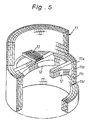
- a heat-resisting annular seal member 24a of ceramic fibers is interposed between the upper cylidrical portion 22b of the uppermost filter assembly unit 20 and the gas induction duct 15 and retained by an annular thrust plate 24b.
- the upper cylindrical portion 22b of the uppermost filter assembly unit 20 is assembled to be axially displaceable relative to the gas induction duct 15.
- a heat-resisting annular seal member similar to the annular seal member 24a is interposed between the upper and lower cylindrical portions 22b and 22c to permit relative displacement of the support housings coupled with each other.
- the gas induction passage P 1 formed in the internal upright support housings 22 is communicated with the gas induction ducts 14, 15 at its upper end and communicated with the dust discharge duct 11f at its lower end.
- the vertical discharge passages P 2 are formed among the filter assemblies 21 to discharge purified gases therethrough.
- the filter assemblies 21 of the respective filter assembly units 20 each are engaged at their outside corners with a pair of circumferentially spaced throttle plates 16 and a pair of vertically spaced partition plates 17 which are provided along the internal peripheral surface of housing 11.
- the pair of circumferentially spaced throttle plates 16 are assembled with the pair of vertically spaced partition plates 17 to form a cavity R which contains therein a reverse washing means 30.
- the throttle plates 16 each are formed with a semi-circular opening 16a through which the cavity R is communicated with the gas discharge passage P 2 .
- the reverse washing means 30 includes a radial supply pipe 31, a vertical main pipe 32 connected to the radial supply pipe 31 and a plurality of vertically spaced lateral sub-pipes 33 connected to the vertical main pipe 32.
- the radial supply pipe 31 extends outwardly through the peripheral wall of housing 11 and connected to a supply source of gas or air under pressure (not shown).
- the lateral sub-pipes 33 are connected to the vertical main pipe 32 perpendicularly thereto in parallel to one another and opposed to each outside of the filter elements 21a.
- the lateral sub-pipes 33 each are formed with a plurality of jet holes which are opened toward the respective filter elements 21a to intermittently spurt jet streams of washing gas or air into the discharge axial passages of the respective filter elements 21a.
- the upper cylindrical portions 22b of the respective internal upright support housings 22 are axially displaced relative to the upper induction duct 15 and the lower cylindrical portions 22c at each joint portion therewith. Accordingly, in spite of the lowermost internal support housing 22 being mounted on the lower end of the cylindrical housing 11, even if the gas induction duct 15 and internal upright support housings 22 are thermally expanded or contracted, the component parts of the dust collecting apparatus will be protected from thermal stress applied thereto.
- the filter assemblies 21 each are composed of the plurality of filter elements 21a
- the filter assembly units 20 each are composed of the plurality of filter assemblies 21, and the filter assembly units 20 are arranged at vertically spaced plural steps. With such an arrangement of the filter assembly units 20, it is able to noticeably enhance the gas purifying performance of the dust collecting apparatus.
- the reverse washing means 30 is provided within the respective cavities R formed at each outside of the filter assemblies 21, and the discharge passages P 2 each are communicated with the respective cavities R through the respective semi-circular openings 16a of throttle plates 16.
- the throttle plates 16 act to prevent reverse flow of washing gas or air spurted from the reverse washing means 30 thereby to effectively supply the washing gas or air into the axial discharge passages of filter elements 21a. This is useful to enhance the washing efficiency of the filter elements 21a.
Landscapes
- Chemical & Material Sciences (AREA)
- Chemical Kinetics & Catalysis (AREA)
- Physics & Mathematics (AREA)
- Geometry (AREA)
- Filtering Of Dispersed Particles In Gases (AREA)
Claims (7)
- Appareil de collecte de poussières pour la purification des gaz haute température qui lui sont appliqués pour être purifiés, l'appareil de collecte de poussières ayant un logement cylindrique dressé (11) pourvu d'un logement de support dressé interne (22), un certain nombre de poutres latérales de support (12, 13) qui bordent un passage vertical d'induction de gaz (P1) et un passage verticale d'évacuation (P2) et au moins une unité d'assemblages de filtres (20) composée d'un certain nombre d'assemblages de filtres (21) circonférentiellement espacés, placés sur les poutres de support et couplés d'une manière étanche à l'air au logement de support interne dressé, de manière que les assemblages de filtres (21) soient exposés à l'une de leurs extrémités au passage vertical d'induction de gaz (P1) et à l'autre de leurs extrémités au passage vertical d'évacuation (P2), chacun desdits assemblages de filtre (21) étant chacun composé d'un certain nombre d'éléments de filtre (21a) assemblés en une unité, chacun desdits éléments de filtres (21a) étant fait d'une matière céramique poreuse et ayant une structure cellulaire à paroi mince formée avec un certain de passages axiaux séparés les uns des autres par des parois minces de séparation, où un premier groupe desdits passages axiaux est ouvert aux premières extrémités pour y introduire des gaz à haute température à purifier par le passage vertical d'induction de gaz et fermé aux autres extrémités alors qu'un second groupe desdits passages axiaux est fermé aux premières extrémités et ouvert aux autres extrémités pour évacuer les gaz purifiés dans le passage vertical d'évacuation,
caractérisé en ce que lesdites poutres latérales de support (12, 13) sont montées à la surface interne dudit logement cylindrique dressé, ledit logement interne de support dressé (22) est disposé dans ledit logement cylindrique dressé (11) concentriquement à celui-ci et intérieurement auxdits assemblages de filtres (21) pour former le passage vertical d'induction de gaz (P1), le logement cylindrique (11) a un certain nombre desdits passages verticaux d'évacuation (P2) qui sont circonférentiellement espacés et placés le long d'une surface périphérique interne dudit logement cylindrique, lesdits assemblages de filtres (21) sont couplés à leurs extrémités internes avec des ouvertures correspondantes (22d) formées dans ledit logement de support (22) pour les connecter audit passage vertical d'induction de gaz (P1), à l'aide de plaques d'étanchéité (23) engageant les assemblages de filtres sur les périphéries des ouvertures (22d) du logement de support (22), l'extrémité inférieure dudit logement interne dressé de support (22) est montée sur une extrémité inférieure dudit logement cylindrique dressé (11) pour une connexion à une trémie collectrice de poussières et ledit logement interne dressé de support (22) est couplé verticalement déplaçable, d'une façon étanche à l'air, à son extrémité supérieure (22b), à une gaine d'induction de gaz (15) connectée à une extrémité supérieure dudit logement cylindrique (11). - Appareil de collecte de poussières selon la revendication 1, où ladite unité d'assemblages de filtres (20) comporte plusieurs groupes desdits assemblages de filtres circonférentiellement espacés (21) verticalement montés les uns au dessus des autres sur les poutres de support (12, 13) dudit logement cylindrique dressé (11).
- Appareil de collecte de poussières selon la revendication 1 ou 2, où lesdits poutres latérales de support (12, 13) sont prévues en un certain nombre d'échelons verticalement espacés dans ledit logement cylindrique dressé (11) et un certain nombre desdites unités d'assemblages de filtres (20) sont montées sur lesdites poutres latérales de support (12, 13) aux échelons respectifs.
- Appareil de collecte de poussières selon la revendication 1, 2 ou 3, où lesdites poutres latérales de support (12, 13) s'étendent horizontalement.
- Appareil de collecte de poussières selon l'une quelconque des revendications 1 à 4, où un moyen de contre-lavage (30) est prévu à chaque extérieur desdits assemblages de filtres (21) pour éjecter des courants de gaz ou d'air dans le second groupe desdits passages axiaux desdits éléments de filtre (21a).
- Appareil de collecte de poussières selon la revendication 5, où un moyen d'étranglement (16, 16a) est prévu entre ledit moyen de contre-lavage (30) et chacun desdits passages verticaux d'évacuation (P2) pour empêcher un écoulement inverse du gaz de lavage ou de l'air dans lesdits passages verticaux d'évacuation (P2).
- Appareil de collecte de poussières selon l'une quelconque des revendications 1 à 6, où un organe formant joint annulaire thermo-résistant (24a) en fibres céramiques est interposé entre l'extrémité supérieure (22b) dudit logement interne dressé de support (22) et une portion extrême inférieure de ladite gaine d'induction de gaz (15) et est retenu par une plaque annulaire de poussée (24b).
Applications Claiming Priority (2)
| Application Number | Priority Date | Filing Date | Title |
|---|---|---|---|
| JP51855/93 | 1993-03-12 | ||
| JP5051855A JP2718615B2 (ja) | 1993-03-12 | 1993-03-12 | 高温ガス用集塵装置 |
Publications (2)
| Publication Number | Publication Date |
|---|---|
| EP0620034A1 EP0620034A1 (fr) | 1994-10-19 |
| EP0620034B1 true EP0620034B1 (fr) | 1998-10-28 |
Family
ID=12898481
Family Applications (1)
| Application Number | Title | Priority Date | Filing Date |
|---|---|---|---|
| EP94301741A Expired - Lifetime EP0620034B1 (fr) | 1993-03-12 | 1994-03-11 | Appareil de collection de poussière pour gaz à haute température |
Country Status (4)
| Country | Link |
|---|---|
| US (1) | US5421847A (fr) |
| EP (1) | EP0620034B1 (fr) |
| JP (1) | JP2718615B2 (fr) |
| DE (1) | DE69414161T2 (fr) |
Families Citing this family (3)
| Publication number | Priority date | Publication date | Assignee | Title |
|---|---|---|---|---|
| JP3066247B2 (ja) * | 1994-05-31 | 2000-07-17 | 日本碍子株式会社 | 集塵装置 |
| US5518513A (en) * | 1994-09-16 | 1996-05-21 | Mitsubishi Jukogyo Kabushiki Kaisha | Dust removing apparatus |
| US5944859A (en) * | 1996-05-06 | 1999-08-31 | Siemens Westinghouse Power Corporation | Hot gas filter and system assembly |
Family Cites Families (18)
| Publication number | Priority date | Publication date | Assignee | Title |
|---|---|---|---|---|
| JPS556042U (fr) * | 1978-06-27 | 1980-01-16 | ||
| US4343631A (en) * | 1981-01-30 | 1982-08-10 | Westinghouse Electric Corp. | Hot gas particulate removal |
| US4419108A (en) * | 1982-02-22 | 1983-12-06 | Corning Glass Works | Filter apparatus and method of filtering |
| US4416675A (en) * | 1982-02-22 | 1983-11-22 | Corning Glass Works | High capacity solid particulate filter apparatus |
| EP0124863B1 (fr) * | 1983-05-06 | 1991-04-03 | Asahi Glass Company Ltd. | Procédé pour traiter des gaz contenant de la poussière et dispositif pour la mise en oeuvre du procédé |
| US4737176A (en) * | 1986-05-19 | 1988-04-12 | The United States Of America As Represented By The United States Department Of Energy | Hot gas cross flow filtering module |
| US4830749A (en) * | 1986-07-15 | 1989-05-16 | Ngk Insulators, Ltd. | Liquid waste filtering apparatus |
| IT1196822B (it) * | 1986-12-05 | 1988-11-25 | Iveco Fiat | Filtro autorigenerante per i gas di scarico di un motore a combustione interna |
| EP0317501A1 (fr) * | 1987-11-18 | 1989-05-24 | Alusuisse-Lonza Services Ag | Filtre pour l'épuration des gaz d'échappement de moteurs diesel |
| US4830642A (en) * | 1988-02-19 | 1989-05-16 | Cv International, Inc. | Filter system with in situ cleaning of an operating filter unit |
| US4904287A (en) * | 1988-12-22 | 1990-02-27 | Electric Power Research Institute | Compact ceramic tube filter array high-temperature gas filtration |
| US4960448A (en) * | 1989-10-16 | 1990-10-02 | Universal Porosics, Inc. | High temperature gas filter |
| DE3941321C2 (de) * | 1989-12-14 | 1993-10-14 | Herbert Huettlin | Filteranordnung zum Entstauben von Gasen |
| DE4030086C1 (fr) * | 1990-09-21 | 1991-12-12 | Herbert 7853 Steinen De Huettlin | |
| US5078760A (en) * | 1991-02-11 | 1992-01-07 | Westinghouse Electric Corp. | Separation of particulate from gases produced by combustion of fossil material |
| JPH0661416B2 (ja) * | 1991-02-25 | 1994-08-17 | 日本碍子株式会社 | 排ガス処理装置 |
| JPH0661417B2 (ja) * | 1991-05-29 | 1994-08-17 | 日本碍子株式会社 | ガス処理装置 |
| JP2945800B2 (ja) * | 1992-03-16 | 1999-09-06 | 日本碍子株式会社 | ガス処理装置 |
-
1993
- 1993-03-12 JP JP5051855A patent/JP2718615B2/ja not_active Expired - Lifetime
-
1994
- 1994-03-11 DE DE69414161T patent/DE69414161T2/de not_active Expired - Fee Related
- 1994-03-11 US US08/208,718 patent/US5421847A/en not_active Expired - Fee Related
- 1994-03-11 EP EP94301741A patent/EP0620034B1/fr not_active Expired - Lifetime
Also Published As
| Publication number | Publication date |
|---|---|
| JP2718615B2 (ja) | 1998-02-25 |
| DE69414161T2 (de) | 1999-04-22 |
| US5421847A (en) | 1995-06-06 |
| DE69414161D1 (de) | 1998-12-03 |
| JPH06262017A (ja) | 1994-09-20 |
| EP0620034A1 (fr) | 1994-10-19 |
Similar Documents
| Publication | Publication Date | Title |
|---|---|---|
| US5601626A (en) | Support construction of filter element in dust collecting apparatus | |
| FI84979B (fi) | Filter foer separering av partiklar fraon en het gasstroem. | |
| EP0501733B1 (fr) | Dispositif d'épuration des gaz d'échappement | |
| KR950007911B1 (ko) | 고온 가스로부터의 입자 물질 분리 장치 | |
| KR100365121B1 (ko) | 필터 시스템 | |
| JPS6012115A (ja) | 垂直方向段型微粒子濾過装置 | |
| JPS62225221A (ja) | パテイキユレ−トトラツプ | |
| JPH05261228A (ja) | 高温高圧ガスの除塵装置 | |
| US5474585A (en) | Filtering apparatus | |
| US5037461A (en) | Filtration apparatus | |
| EP0944422B1 (fr) | Ensemble filtre/systeme de gaz chaud | |
| EP0620034B1 (fr) | Appareil de collection de poussière pour gaz à haute température | |
| US5284498A (en) | Cylindrical filters in a tube sheet for cleaning high temperature gases | |
| US5593471A (en) | Dust collecting apparatus | |
| US5152815A (en) | Type 114 tiered filter | |
| KR101591568B1 (ko) | 고효율 집진기 | |
| WO1994014522A1 (fr) | Filtre | |
| RU2147915C1 (ru) | Регенерируемый фильтр для тонкой очистки газов от пыли | |
| JPH11114338A (ja) | 高温排ガス処理用のセラミック製フィルタ装置 | |
| JPH0543846Y2 (fr) | ||
| JPH05345109A (ja) | 高温ガス濾過装置 | |
| RU2182847C1 (ru) | Аппарат каталитического окисления | |
| SU1535595A1 (ru) | Фильтр дл очистки газов от пыли | |
| JPH05231126A (ja) | フィルタモジュールおよびディーゼル機関用パティキュレートトラップ | |
| JP2003251125A (ja) | ガスフィルター装置 |
Legal Events
| Date | Code | Title | Description |
|---|---|---|---|
| PUAI | Public reference made under article 153(3) epc to a published international application that has entered the european phase |
Free format text: ORIGINAL CODE: 0009012 |
|
| AK | Designated contracting states |
Kind code of ref document: A1 Designated state(s): DE FR GB |
|
| 17P | Request for examination filed |
Effective date: 19941205 |
|
| 17Q | First examination report despatched |
Effective date: 19951110 |
|
| GRAG | Despatch of communication of intention to grant |
Free format text: ORIGINAL CODE: EPIDOS AGRA |
|
| GRAG | Despatch of communication of intention to grant |
Free format text: ORIGINAL CODE: EPIDOS AGRA |
|
| GRAG | Despatch of communication of intention to grant |
Free format text: ORIGINAL CODE: EPIDOS AGRA |
|
| GRAH | Despatch of communication of intention to grant a patent |
Free format text: ORIGINAL CODE: EPIDOS IGRA |
|
| GRAH | Despatch of communication of intention to grant a patent |
Free format text: ORIGINAL CODE: EPIDOS IGRA |
|
| GRAA | (expected) grant |
Free format text: ORIGINAL CODE: 0009210 |
|
| AK | Designated contracting states |
Kind code of ref document: B1 Designated state(s): DE FR GB |
|
| REF | Corresponds to: |
Ref document number: 69414161 Country of ref document: DE Date of ref document: 19981203 |
|
| ET | Fr: translation filed | ||
| PLBE | No opposition filed within time limit |
Free format text: ORIGINAL CODE: 0009261 |
|
| STAA | Information on the status of an ep patent application or granted ep patent |
Free format text: STATUS: NO OPPOSITION FILED WITHIN TIME LIMIT |
|
| 26N | No opposition filed | ||
| REG | Reference to a national code |
Ref country code: GB Ref legal event code: IF02 |
|
| PGFP | Annual fee paid to national office [announced via postgrant information from national office to epo] |
Ref country code: GB Payment date: 20020301 Year of fee payment: 9 |
|
| PGFP | Annual fee paid to national office [announced via postgrant information from national office to epo] |
Ref country code: FR Payment date: 20020320 Year of fee payment: 9 |
|
| PGFP | Annual fee paid to national office [announced via postgrant information from national office to epo] |
Ref country code: DE Payment date: 20020527 Year of fee payment: 9 |
|
| PG25 | Lapsed in a contracting state [announced via postgrant information from national office to epo] |
Ref country code: GB Free format text: LAPSE BECAUSE OF NON-PAYMENT OF DUE FEES Effective date: 20030311 |
|
| PG25 | Lapsed in a contracting state [announced via postgrant information from national office to epo] |
Ref country code: DE Free format text: LAPSE BECAUSE OF NON-PAYMENT OF DUE FEES Effective date: 20031001 |
|
| GBPC | Gb: european patent ceased through non-payment of renewal fee |
Effective date: 20030311 |
|
| PG25 | Lapsed in a contracting state [announced via postgrant information from national office to epo] |
Ref country code: FR Free format text: LAPSE BECAUSE OF NON-PAYMENT OF DUE FEES Effective date: 20031127 |
|
| REG | Reference to a national code |
Ref country code: FR Ref legal event code: ST |