EP0620059B1 - Procédé pour fabriquer un fil métallique à section tronçonique - Google Patents
Procédé pour fabriquer un fil métallique à section tronçonique Download PDFInfo
- Publication number
- EP0620059B1 EP0620059B1 EP94105805A EP94105805A EP0620059B1 EP 0620059 B1 EP0620059 B1 EP 0620059B1 EP 94105805 A EP94105805 A EP 94105805A EP 94105805 A EP94105805 A EP 94105805A EP 0620059 B1 EP0620059 B1 EP 0620059B1
- Authority
- EP
- European Patent Office
- Prior art keywords
- wires
- starting
- profile
- wire
- steel
- Prior art date
- Legal status (The legal status is an assumption and is not a legal conclusion. Google has not performed a legal analysis and makes no representation as to the accuracy of the status listed.)
- Expired - Lifetime
Links
Images

Classifications
-
- B—PERFORMING OPERATIONS; TRANSPORTING
- B23—MACHINE TOOLS; METAL-WORKING NOT OTHERWISE PROVIDED FOR
- B23K—SOLDERING OR UNSOLDERING; WELDING; CLADDING OR PLATING BY SOLDERING OR WELDING; CUTTING BY APPLYING HEAT LOCALLY, e.g. FLAME CUTTING; WORKING BY LASER BEAM
- B23K15/00—Electron-beam welding or cutting
- B23K15/0046—Welding
- B23K15/0053—Seam welding
- B23K15/006—Seam welding of rectilinear seams
-
- B—PERFORMING OPERATIONS; TRANSPORTING
- B21—MECHANICAL METAL-WORKING WITHOUT ESSENTIALLY REMOVING MATERIAL; PUNCHING METAL
- B21B—ROLLING OF METAL
- B21B1/00—Metal-rolling methods or mills for making semi-finished products of solid or profiled cross-section; Sequence of operations in milling trains; Layout of rolling-mill plant, e.g. grouping of stands; Succession of passes or of sectional pass alternations
- B21B1/08—Metal-rolling methods or mills for making semi-finished products of solid or profiled cross-section; Sequence of operations in milling trains; Layout of rolling-mill plant, e.g. grouping of stands; Succession of passes or of sectional pass alternations for rolling structural sections, i.e. work of special cross-section, e.g. angle steel
-
- B—PERFORMING OPERATIONS; TRANSPORTING
- B21—MECHANICAL METAL-WORKING WITHOUT ESSENTIALLY REMOVING MATERIAL; PUNCHING METAL
- B21F—WORKING OR PROCESSING OF METAL WIRE
- B21F15/00—Connecting wire to wire or other metallic material or objects; Connecting parts by means of wire
- B21F15/02—Connecting wire to wire or other metallic material or objects; Connecting parts by means of wire wire with wire
- B21F15/06—Connecting wire to wire or other metallic material or objects; Connecting parts by means of wire wire with wire with additional connecting elements or material
- B21F15/08—Connecting wire to wire or other metallic material or objects; Connecting parts by means of wire wire with wire with additional connecting elements or material making use of soldering or welding
-
- B—PERFORMING OPERATIONS; TRANSPORTING
- B21—MECHANICAL METAL-WORKING WITHOUT ESSENTIALLY REMOVING MATERIAL; PUNCHING METAL
- B21B—ROLLING OF METAL
- B21B1/00—Metal-rolling methods or mills for making semi-finished products of solid or profiled cross-section; Sequence of operations in milling trains; Layout of rolling-mill plant, e.g. grouping of stands; Succession of passes or of sectional pass alternations
- B21B1/08—Metal-rolling methods or mills for making semi-finished products of solid or profiled cross-section; Sequence of operations in milling trains; Layout of rolling-mill plant, e.g. grouping of stands; Succession of passes or of sectional pass alternations for rolling structural sections, i.e. work of special cross-section, e.g. angle steel
- B21B1/09—L-sections
-
- B—PERFORMING OPERATIONS; TRANSPORTING
- B21—MECHANICAL METAL-WORKING WITHOUT ESSENTIALLY REMOVING MATERIAL; PUNCHING METAL
- B21B—ROLLING OF METAL
- B21B15/00—Arrangements for performing additional metal-working operations specially combined with or arranged in, or specially adapted for use in connection with, metal-rolling mills
- B21B2015/0092—Welding in the rolling direction
-
- B—PERFORMING OPERATIONS; TRANSPORTING
- B21—MECHANICAL METAL-WORKING WITHOUT ESSENTIALLY REMOVING MATERIAL; PUNCHING METAL
- B21B—ROLLING OF METAL
- B21B3/00—Rolling materials of special alloys so far as the composition of the alloy requires or permits special rolling methods or sequences ; Rolling of aluminium, copper, zinc or other non-ferrous metals
- B21B3/02—Rolling special iron alloys, e.g. stainless steel
Definitions
- the invention relates to a method for the production of profile wire by profile pressing of the starting wire, in particular for the production of all-steel fittings.
- profile wires are usually produced by profile rolling starting wires with a substantially circular cross-section into the desired shape or the desired profile.
- a disadvantage of the known methods is that with them the end profile by deforming the output wire can be achieved with a uniform starting cross-section, which can only be achieved by a large number of deformation steps.
- the invention has for its object to further develop the known method for the production of profile wire so that the finished process product can be produced in a simple manner while avoiding unnecessary process steps.
- this object is achieved by joining and connecting at least two output wires, along regions running essentially in the longitudinal direction of the wires and by profile pressing the connected output wires while keeping the ratios of the cross-sectional areas perpendicular to the longitudinal direction of the output wires relative to one another.
- the profiled wires produced have no curvature along their longitudinal extent. Furthermore, there are no curvatures or other deformations of the connection areas along which the starting wires have been connected to one another before the pressing in the case of profiled wires produced by this method.
- Another advantage of the method according to the invention is furthermore that the roughnesses generated during the production of the connection between the wires along the connection area or areas are practically inevitably eliminated by the subsequent molding processes.
- the areas along which the output wires are joined can be selected so that the output wires can be connected to one another in a simple manner, while the connection areas in the profile wire obtained by the compression molding are no longer accessible for the production of a fixed connection have to.
- the fact that the foot part and blade part of such profiled wires should have different material properties has proven to be disadvantageous. It is advantageous for the foot section if it is very flexible so that it does not break or tear when it is pulled onto the roller, whereas the sheet section should be characterized by high wear resistance in order to ensure a long service life of the clothing. Due to these different material requirements, there is a great limitation in the selection of the starting materials when carrying out the known processes.
- At least two of the output wires to be processed consist of different materials.
- at least one wire can be made of unalloyed steel (e.g. C 10 steel) and at least one wire made of alloy steel.
- the wires are preferably connected by welding. Electron beam welding in a high vacuum is particularly preferred because this ensures a particularly clean connection without additives.
- the wires can be annealed to reduce any increases in tension and hardness that may have occurred.
- the profile pressing can be done by profile rolling and / or profile drawing. Depending on the material and the required degree of deformation, the rolling and / or drawing can take place in several cold and / or hot rolling and / or drawing stages. It is again particularly advantageous to anneal the wires after each cold rolling or drawing step in order to return any tension and hardening that may have occurred.
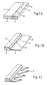
- two output wires 1 and 2 are used, of which the output wire 1 consists of unalloyed C 10 steel and the output wire 2 consists of high-alloy and wear-resistant CrMo steel.
- These output wires 1 and 2 are first brought into a rectangular cross section 3 and 4, respectively, in a manner not illustrated in any more detail, and, as shown in FIG. 1 a, joined together along a connecting region 5.
- the output wires 1 and 2 are shaped so that the narrow sides of the rectangular cross sections match in length.
- the wires are joined together so that the narrow sides of the output wires coincide with each other.
- the wires When assembled, the wires are connected to one another in a high vacuum by electron beam welding.
- the resulting weld seam which extends in a straight line in the longitudinal direction, is designated by 6 in FIG. 1A.
- the interconnected wires are annealed to reduce the stresses and differences in hardness that have occurred.
- the joined wires are profile-pressed in several cold rolling stages. Each individual cold rolling stage is ended before the individual duct wires have reached their maximum deformability. Tensions and differences in hardness that occur during cold rolling are reduced by annealing after each cold rolling step.
- the cold rolling is carried out in such a way that the ratios of the cross-sectional areas 3 and 4 or 3 'and 4' to one another remain the same. This ensures that the surfaces 5 and 5 ', along which the output wires are connected to one another, are not deformed at right angles to the longitudinal direction.
- the profile wire shown in Fig. 1B can serve as a starting product for an all-steel set.
- the section 1 'made of unalloyed C 10 steel serves as the foot part of the set and the section 2' made of high-alloy CrMo steel serves as the sheet part.
- teeth 7 are punched into the sheet part 2 'and these are then hardened by annealing at about 1200 ° C. and subsequent quenching. To improve the hardness properties of the teeth, they are left on after hardening. Since the profile wire consists of two welded parts, it is not fully hardened.
- the method according to the invention can be used to produce an all-steel fitting, the base part of which has good flexibility and the leaf part of which has high wear resistance, without being subject to restrictions in the selection of the starting materials.
- the method for producing an all-steel set according to FIG. 2 differs only in that 1 that the narrow side of the wire 12 comes to rest on the long side of the wire 11 and the connection area 15 only part of the long side of the wire 11 when the output wires 11 and 12, which are again brought to a rectangular cross section, are joined together covers.
- the profile pressing is carried out again so that the ratios of the cross-sectional areas 13 and 14 or 13 'and 14' to each other remain constant.
- the weld seam 16 also extends in a straight line in the longitudinal direction in the intermediate product shown in FIG. 2B, and the connection region 15 ′ has no deformation in the longitudinal direction.
- the method according to the invention is not limited to the possible embodiments described with reference to the drawing.
- other materials may be used for the output wires, more than two output wires joined together, or other methods of making the connection between the wires, such as e.g. Brazing, induction welding or cold welding can be used.
- ceramic materials can also be used as the material for the output wires.
Landscapes
- Engineering & Computer Science (AREA)
- Mechanical Engineering (AREA)
- Wire Processing (AREA)
- Electrical Discharge Machining, Electrochemical Machining, And Combined Machining (AREA)
- Nonmetallic Welding Materials (AREA)
- Yarns And Mechanical Finishing Of Yarns Or Ropes (AREA)
- Metal Rolling (AREA)
- Welding Or Cutting Using Electron Beams (AREA)
- Forging (AREA)
- Preliminary Treatment Of Fibers (AREA)
- Pressure Welding/Diffusion-Bonding (AREA)
Claims (17)
- Procédé de fabrication de fils métalliques profilés, par pressage de profilage du fil métallique initial, en particulier pour la fabrication de garnitures tout acier, comportant les étapes ci-après :a) assemblage et liaison d'au moins deux fils métalliques initiaux, le long de zones s'étendant sensiblement dans la direction longitudinale des fils métalliques,b) pressage de profilage des fils métalliques initiaux reliés, avec maintien constant des caractéristiques des surfaces de sections transversales, perpendiculairement par rapport à la direction longitudinale des fils métalliques initiaux, l'un par rapport à l'autre.
- Procédé selon la revendication 1, caractérisé en ce qu'au moins deux fils métalliques initiaux sont composés de matériaux différents.
- Procédé selon l'une des revendications précédentes, caractérisé en ce qu'au moins un fil métallique initial est composé d'acier non allié et au moins un fil métallique initial est composé d'acier allié.
- Procédé selon la revendication 3, caractérisé en ce que l'acier non allié est un acier C10.
- Procédé selon l'une des revendications précédentes, caractérisé en ce qu'au moins un fil métallique initial est pressé au profil avant assemblage.
- Procédé selon l'une des revendications précédentes, caractérisé en ce que la liaison s'effectue par soudage.
- Procédé selon la revendication 6, caractérisé en ce que le soudage s'effectue par soudage à bombardement électronique, sous-vide poussé, sans adjonction d'additifs.
- Procédé selon l'une des revendications 6 ou 7, caractérisé en ce que les fils métalliques initiaux sont recuits après soudage.
- Procédé selon l'une des revendications précédentes, caractérisé en ce que le pressage de profilage s'effectue par laminage aux rouleaux de profilage et/ou par étirage de profilage.
- Procédé selon la revendication 9, caractérisé en ce que le laminage aux rouleaux de profilage et/ou l'étirage de profilage s'effectuent en une combinaison de plusieurs étapes de laminage aux rouleaux à froid et/ou à chaud et/ou d'étirage.
- Procédé selon la revendication 10, caractérisé en ce que les fils métalliques initiaux sont chaque fois recuits après les étapes de laminage à rouleaux à froid et/ou d'étirage.
- Procédé selon l'une des revendications précédentes, caractérisé en ce que deux fils métalliques initiaux sont assemblés et reliés.
- Procédé selon la revendication 12, caractérisé en ce que deux fils métalliques initiaux sont des fils métalliques plats à profil rectangulaire, produits par laminage aux rouleaux.
- Procédé selon la revendication 13, caractérisé en ce que les fils métalliques initiaux assemblés et reliés sont pressés, pour obtenir la forme d'une garniture tout acier, avec une partie pied et une partie lame.
- Procédé selon la revendication 14, caractérisé en ce que la partie pied est en acier non allié et la partie lame est en acier allié.
- Procédé selon l'une des revendications 14 ou 15, caractérisé en ce que des dents sot découpées par estampage dans la partie lame après laminage et ces dents sont durcies par trempage.
- Procédé selon la revendication 16, caractérisé en ce que les dents durcies par trempage sont soumises à un traitement de revenu.
Applications Claiming Priority (2)
| Application Number | Priority Date | Filing Date | Title |
|---|---|---|---|
| DE4312122 | 1993-04-14 | ||
| DE4312122A DE4312122A1 (de) | 1993-04-14 | 1993-04-14 | Verfahren zur Herstellung von Profildraht |
Publications (2)
| Publication Number | Publication Date |
|---|---|
| EP0620059A1 EP0620059A1 (fr) | 1994-10-19 |
| EP0620059B1 true EP0620059B1 (fr) | 1997-03-05 |
Family
ID=6485416
Family Applications (1)
| Application Number | Title | Priority Date | Filing Date |
|---|---|---|---|
| EP94105805A Expired - Lifetime EP0620059B1 (fr) | 1993-04-14 | 1994-04-14 | Procédé pour fabriquer un fil métallique à section tronçonique |
Country Status (6)
| Country | Link |
|---|---|
| US (1) | US5452627A (fr) |
| EP (1) | EP0620059B1 (fr) |
| JP (1) | JPH06304692A (fr) |
| AT (1) | ATE149389T1 (fr) |
| DE (2) | DE4312122A1 (fr) |
| ES (1) | ES2061426T3 (fr) |
Families Citing this family (10)
| Publication number | Priority date | Publication date | Assignee | Title |
|---|---|---|---|---|
| DE19616787C1 (de) * | 1996-04-26 | 1997-10-02 | Riwo Drahtwerk Gmbh | Profildraht zur Verwendung auf Karden |
| AT500151B1 (de) * | 2002-08-12 | 2007-09-15 | Boehler Uddeholm Prec Strip Gm | Vormaterial für sägeblätter oder sägebänder |
| DE102005025627B3 (de) * | 2005-06-03 | 2006-10-05 | Graf + Cie Ag | Verfahren und Vorrichtung zum Herstellen von Sägezahn- und Ganzstahlgarnituren sowie Sägezahndraht |
| DE102006009732A1 (de) * | 2006-03-02 | 2007-09-06 | Graf, Ralph A. | Kämmeinrichtung für einen Rundkamm und Vrfahren zur Herstellung der Kämmeinrichtung |
| DE102006030763A1 (de) * | 2006-06-23 | 2008-01-03 | Wilhelm Stahlecker Gmbh | Zahngarnitur für einen Kamm einer Kämm-Maschine |
| CN101745780B (zh) * | 2008-12-10 | 2011-04-13 | 上海工程技术大学 | 一种粗线径钢丝送料槽板的制造方法 |
| CN107186436B (zh) * | 2017-04-27 | 2019-12-27 | 嘉峪关天源新材料有限责任公司 | 一种平环高梯度强磁选机用复合聚磁介质的制造方法 |
| CN110524102B (zh) * | 2019-08-22 | 2021-04-02 | 山东省科学院新材料研究所 | 一种有效增强焊接接头质量的装置及方法 |
| CN113020262B (zh) * | 2021-03-25 | 2022-11-08 | 太原理工大学 | 一种预制交叉波纹界面的金属复合板轧制方法 |
| CN116586812B (zh) * | 2023-05-22 | 2025-12-30 | 大连理工大学 | 一种用于提升构筑件界面结合效果的基材表面 |
Family Cites Families (9)
| Publication number | Priority date | Publication date | Assignee | Title |
|---|---|---|---|---|
| US2786788A (en) * | 1953-11-16 | 1957-03-26 | Doall Co | High speed tool steel saw band and method of making the same |
| US3387338A (en) * | 1964-10-30 | 1968-06-11 | Kanai Hiroyuki | Metallic card clothing |
| US3593600A (en) * | 1969-04-29 | 1971-07-20 | Continental Can Co | Band saw blade apparatus and methods |
| US3835526A (en) * | 1971-02-03 | 1974-09-17 | Rmi Co | Method of forming tapered metal pieces |
| US3737979A (en) * | 1971-08-05 | 1973-06-12 | Anaconda American Brass Co | Method of manufacturing longitudinally welded strips of different thicknesses and widths |
| US3834207A (en) * | 1972-08-30 | 1974-09-10 | Anaconda American Brass Co | Method and apparatus for forming an accurately dimensioned metal strip having varying thickness |
| US4476194A (en) * | 1982-11-10 | 1984-10-09 | United Technologies Corporation | Contour forming conical shapes |
| AT391826B (de) * | 1987-12-04 | 1990-12-10 | Boehler Gmbh | Bi-metallband fuer metallsaegen |
| US5215245A (en) * | 1991-04-03 | 1993-06-01 | Carrier Corporation | Method for roll embossing metal strip |
-
1993
- 1993-04-14 DE DE4312122A patent/DE4312122A1/de not_active Withdrawn
-
1994
- 1994-03-31 JP JP6096831A patent/JPH06304692A/ja active Pending
- 1994-04-14 EP EP94105805A patent/EP0620059B1/fr not_active Expired - Lifetime
- 1994-04-14 DE DE59401874T patent/DE59401874D1/de not_active Expired - Fee Related
- 1994-04-14 US US08/227,543 patent/US5452627A/en not_active Expired - Lifetime
- 1994-04-14 ES ES94105805T patent/ES2061426T3/es not_active Expired - Lifetime
- 1994-04-14 AT AT94105805T patent/ATE149389T1/de not_active IP Right Cessation
Also Published As
| Publication number | Publication date |
|---|---|
| ES2061426T1 (es) | 1994-12-16 |
| US5452627A (en) | 1995-09-26 |
| EP0620059A1 (fr) | 1994-10-19 |
| ATE149389T1 (de) | 1997-03-15 |
| DE59401874D1 (de) | 1997-04-10 |
| JPH06304692A (ja) | 1994-11-01 |
| DE4312122A1 (de) | 1994-10-20 |
| ES2061426T3 (es) | 1997-05-16 |
Similar Documents
| Publication | Publication Date | Title |
|---|---|---|
| EP2119514B1 (fr) | Procédé pour le dressage d'une bande métallique | |
| DE2723382A1 (de) | Verfahren zur herstellung von stahlfasern fuer stahlbeton | |
| DE3813272A1 (de) | Verbindungsstruktur fuer einen rotor mit welle | |
| DE1503939A1 (de) | Saegeblatt und Verfahren zu seiner Herstellung | |
| DE4200489C2 (de) | Zweiteiliger Ölring und Verfahren zu dessen Herstellung | |
| DE60222785T2 (de) | Verfahren und gerät zur herstellung von schienen | |
| DE69527143T2 (de) | Walzwerk zur herstellung von winkelstahl aus bandstahl | |
| EP0620059A1 (fr) | Procédé pour fabriquer un fil métallique à section tronçonique | |
| DE60023820T2 (de) | Verfahren zur Herstellung von gebogenen und deformierten metallischen Teilen | |
| EP0301228A1 (fr) | Procédé de fabrication de feuillard laminé à chaud | |
| DE1452020A1 (de) | Verfahren zum Walzen von Schienenprofilen | |
| DE2607755A1 (de) | Verfahren zum kaltwalzen einer kontur in metallringen | |
| DE3889030T2 (de) | Hartgezogener Ölvergüteter Stahldraht mit vorgeformtem Durchschnitt und Verfahren zu dessen Herstellung. | |
| DE2757071C3 (de) | Verfahren zum Herstellen gleichzeitig mehrerer Knüppel | |
| EP0849027B1 (fr) | Méthode de fabrication de plaques et bandes profilées | |
| DE19748321A1 (de) | Verfahren zur Herstellung von Material mit modifiziertem Querschnitt | |
| DE69523013T2 (de) | Verfahren zur Herstellung eines Flachstahldraht für Seitenleisten eines Ölrings zur Verwendung in einem Verbrennungsmotor | |
| EP0470512B1 (fr) | Procédé pour dresser des rubans métalliques en courant | |
| EP0965399B1 (fr) | Procédé de fabrication d'un ressort en fil à partir d'un fil métallique dur ayant une section rondée | |
| DE19628714C1 (de) | Verfahren zur Herstellung von Präzisionsstahlrohren | |
| DE60004094T2 (de) | Kaltgeformte, flachgewalzte stahlprofile | |
| DE2923532B1 (de) | Verwendung eines ferritischen rostfreien Stahls fuer in geschweisstem Zustand ohne Waermenachbehandlung gegen interkristalline Korrosion bestaendige Gegenstaende | |
| DE2656277A1 (de) | Verfahren und vorrichtung zum herstellen von betonbewehrungsstaeben | |
| DE69211492T2 (de) | Verfahren zur Herstellung von Stahlbrammen mit quadratischem Querschnitt und danach hergestellte Brammen | |
| AT149549B (de) | Verfahren und Vorrichtung zur Herstellung von Rohren und Profilen aller Art auf kaltem Wege durch Biegen von Bändern oder Blechstreifen. |
Legal Events
| Date | Code | Title | Description |
|---|---|---|---|
| PUAI | Public reference made under article 153(3) epc to a published international application that has entered the european phase |
Free format text: ORIGINAL CODE: 0009012 |
|
| AK | Designated contracting states |
Kind code of ref document: A1 Designated state(s): AT BE DE ES FR IT NL |
|
| ITCL | It: translation for ep claims filed |
Representative=s name: ING. C. GREGORJ S.P.A. |
|
| TCNL | Nl: translation of patent claims filed | ||
| EL | Fr: translation of claims filed | ||
| REG | Reference to a national code |
Ref country code: ES Ref legal event code: BA2A Ref document number: 2061426 Country of ref document: ES Kind code of ref document: T1 |
|
| 17P | Request for examination filed |
Effective date: 19950302 |
|
| GRAG | Despatch of communication of intention to grant |
Free format text: ORIGINAL CODE: EPIDOS AGRA |
|
| 17Q | First examination report despatched |
Effective date: 19960528 |
|
| GRAH | Despatch of communication of intention to grant a patent |
Free format text: ORIGINAL CODE: EPIDOS IGRA |
|
| RBV | Designated contracting states (corrected) |
Designated state(s): AT BE DE ES FR IT NL |
|
| RAP1 | Party data changed (applicant data changed or rights of an application transferred) |
Owner name: GRAF + CIE AG |
|
| GRAH | Despatch of communication of intention to grant a patent |
Free format text: ORIGINAL CODE: EPIDOS IGRA |
|
| GRAA | (expected) grant |
Free format text: ORIGINAL CODE: 0009210 |
|
| AK | Designated contracting states |
Kind code of ref document: B1 Designated state(s): AT BE DE ES FR IT NL |
|
| REF | Corresponds to: |
Ref document number: 149389 Country of ref document: AT Date of ref document: 19970315 Kind code of ref document: T |
|
| REF | Corresponds to: |
Ref document number: 59401874 Country of ref document: DE Date of ref document: 19970410 |
|
| ET | Fr: translation filed | ||
| ITF | It: translation for a ep patent filed | ||
| REG | Reference to a national code |
Ref country code: ES Ref legal event code: FG2A Ref document number: 2061426 Country of ref document: ES Kind code of ref document: T3 |
|
| PLBE | No opposition filed within time limit |
Free format text: ORIGINAL CODE: 0009261 |
|
| STAA | Information on the status of an ep patent application or granted ep patent |
Free format text: STATUS: NO OPPOSITION FILED WITHIN TIME LIMIT |
|
| 26N | No opposition filed | ||
| PGFP | Annual fee paid to national office [announced via postgrant information from national office to epo] |
Ref country code: AT Payment date: 19980427 Year of fee payment: 5 |
|
| PG25 | Lapsed in a contracting state [announced via postgrant information from national office to epo] |
Ref country code: AT Free format text: LAPSE BECAUSE OF NON-PAYMENT OF DUE FEES Effective date: 19990414 |
|
| PGFP | Annual fee paid to national office [announced via postgrant information from national office to epo] |
Ref country code: NL Payment date: 20040429 Year of fee payment: 11 |
|
| PG25 | Lapsed in a contracting state [announced via postgrant information from national office to epo] |
Ref country code: NL Free format text: LAPSE BECAUSE OF NON-PAYMENT OF DUE FEES Effective date: 20051101 |
|
| NLV4 | Nl: lapsed or anulled due to non-payment of the annual fee |
Effective date: 20051101 |
|
| PGFP | Annual fee paid to national office [announced via postgrant information from national office to epo] |
Ref country code: FR Payment date: 20060410 Year of fee payment: 13 |
|
| PGFP | Annual fee paid to national office [announced via postgrant information from national office to epo] |
Ref country code: ES Payment date: 20070412 Year of fee payment: 14 |
|
| PGFP | Annual fee paid to national office [announced via postgrant information from national office to epo] |
Ref country code: DE Payment date: 20070629 Year of fee payment: 14 |
|
| PGFP | Annual fee paid to national office [announced via postgrant information from national office to epo] |
Ref country code: IT Payment date: 20070515 Year of fee payment: 14 Ref country code: BE Payment date: 20070424 Year of fee payment: 14 |
|
| BERE | Be: lapsed |
Owner name: *GRAF + CIE A.G. Effective date: 20080430 |
|
| PG25 | Lapsed in a contracting state [announced via postgrant information from national office to epo] |
Ref country code: DE Free format text: LAPSE BECAUSE OF NON-PAYMENT OF DUE FEES Effective date: 20081101 |
|
| REG | Reference to a national code |
Ref country code: FR Ref legal event code: ST Effective date: 20081231 |
|
| PG25 | Lapsed in a contracting state [announced via postgrant information from national office to epo] |
Ref country code: BE Free format text: LAPSE BECAUSE OF NON-PAYMENT OF DUE FEES Effective date: 20080430 |
|
| PG25 | Lapsed in a contracting state [announced via postgrant information from national office to epo] |
Ref country code: FR Free format text: LAPSE BECAUSE OF NON-PAYMENT OF DUE FEES Effective date: 20080430 |
|
| PG25 | Lapsed in a contracting state [announced via postgrant information from national office to epo] |
Ref country code: FR Free format text: LAPSE BECAUSE OF NON-PAYMENT OF DUE FEES Effective date: 20070430 |
|
| REG | Reference to a national code |
Ref country code: ES Ref legal event code: FD2A Effective date: 20080415 |
|
| PG25 | Lapsed in a contracting state [announced via postgrant information from national office to epo] |
Ref country code: ES Free format text: LAPSE BECAUSE OF NON-PAYMENT OF DUE FEES Effective date: 20080415 |
|
| PG25 | Lapsed in a contracting state [announced via postgrant information from national office to epo] |
Ref country code: IT Free format text: LAPSE BECAUSE OF NON-PAYMENT OF DUE FEES Effective date: 20080414 |