EP0620132A1 - Installation pour entraîner, guider et diriger une roue de véhicule - Google Patents
Installation pour entraîner, guider et diriger une roue de véhicule Download PDFInfo
- Publication number
- EP0620132A1 EP0620132A1 EP94105501A EP94105501A EP0620132A1 EP 0620132 A1 EP0620132 A1 EP 0620132A1 EP 94105501 A EP94105501 A EP 94105501A EP 94105501 A EP94105501 A EP 94105501A EP 0620132 A1 EP0620132 A1 EP 0620132A1
- Authority
- EP
- European Patent Office
- Prior art keywords
- vehicle
- spring cylinder
- steering
- wheel
- vehicle wheel
- Prior art date
- Legal status (The legal status is an assumption and is not a legal conclusion. Google has not performed a legal analysis and makes no representation as to the accuracy of the status listed.)
- Granted
Links
Images

Classifications
-
- B—PERFORMING OPERATIONS; TRANSPORTING
- B60—VEHICLES IN GENERAL
- B60K—ARRANGEMENT OR MOUNTING OF PROPULSION UNITS OR OF TRANSMISSIONS IN VEHICLES; ARRANGEMENT OR MOUNTING OF PLURAL DIVERSE PRIME-MOVERS IN VEHICLES; AUXILIARY DRIVES FOR VEHICLES; INSTRUMENTATION OR DASHBOARDS FOR VEHICLES; ARRANGEMENTS IN CONNECTION WITH COOLING, AIR INTAKE, GAS EXHAUST OR FUEL SUPPLY OF PROPULSION UNITS IN VEHICLES
- B60K7/00—Disposition of motor in, or adjacent to, traction wheel
- B60K7/0015—Disposition of motor in, or adjacent to, traction wheel the motor being hydraulic
-
- B—PERFORMING OPERATIONS; TRANSPORTING
- B60—VEHICLES IN GENERAL
- B60G—VEHICLE SUSPENSION ARRANGEMENTS
- B60G11/00—Resilient suspensions characterised by arrangement, location or kind of springs
- B60G11/26—Resilient suspensions characterised by arrangement, location or kind of springs having fluid springs only, e.g. hydropneumatic springs
- B60G11/265—Resilient suspensions characterised by arrangement, location or kind of springs having fluid springs only, e.g. hydropneumatic springs hydraulic springs
-
- B—PERFORMING OPERATIONS; TRANSPORTING
- B60—VEHICLES IN GENERAL
- B60G—VEHICLE SUSPENSION ARRANGEMENTS
- B60G17/00—Resilient suspensions having means for adjusting the spring or vibration-damper characteristics, for regulating the distance between a supporting surface and a sprung part of vehicle or for locking suspension during use to meet varying vehicular or surface conditions, e.g. due to speed or load
- B60G17/02—Spring characteristics, e.g. mechanical springs and mechanical adjusting means
- B60G17/04—Spring characteristics, e.g. mechanical springs and mechanical adjusting means fluid spring characteristics
- B60G17/0408—Spring characteristics, e.g. mechanical springs and mechanical adjusting means fluid spring characteristics details, e.g. antifreeze for suspension fluid, pumps, retarding means per se
-
- B—PERFORMING OPERATIONS; TRANSPORTING
- B60—VEHICLES IN GENERAL
- B60G—VEHICLE SUSPENSION ARRANGEMENTS
- B60G3/00—Resilient suspensions for a single wheel
- B60G3/01—Resilient suspensions for a single wheel the wheel being mounted for sliding movement, e.g. in or on a vertical guide
-
- B—PERFORMING OPERATIONS; TRANSPORTING
- B60—VEHICLES IN GENERAL
- B60G—VEHICLE SUSPENSION ARRANGEMENTS
- B60G3/00—Resilient suspensions for a single wheel
- B60G3/02—Resilient suspensions for a single wheel with a single pivoted arm
- B60G3/04—Resilient suspensions for a single wheel with a single pivoted arm the arm being essentially transverse to the longitudinal axis of the vehicle
- B60G3/06—Resilient suspensions for a single wheel with a single pivoted arm the arm being essentially transverse to the longitudinal axis of the vehicle the arm being rigid
-
- B—PERFORMING OPERATIONS; TRANSPORTING
- B60—VEHICLES IN GENERAL
- B60G—VEHICLE SUSPENSION ARRANGEMENTS
- B60G3/00—Resilient suspensions for a single wheel
- B60G3/18—Resilient suspensions for a single wheel with two or more pivoted arms, e.g. parallelogram
- B60G3/20—Resilient suspensions for a single wheel with two or more pivoted arms, e.g. parallelogram all arms being rigid
-
- B—PERFORMING OPERATIONS; TRANSPORTING
- B60—VEHICLES IN GENERAL
- B60K—ARRANGEMENT OR MOUNTING OF PROPULSION UNITS OR OF TRANSMISSIONS IN VEHICLES; ARRANGEMENT OR MOUNTING OF PLURAL DIVERSE PRIME-MOVERS IN VEHICLES; AUXILIARY DRIVES FOR VEHICLES; INSTRUMENTATION OR DASHBOARDS FOR VEHICLES; ARRANGEMENTS IN CONNECTION WITH COOLING, AIR INTAKE, GAS EXHAUST OR FUEL SUPPLY OF PROPULSION UNITS IN VEHICLES
- B60K17/00—Arrangement or mounting of transmissions in vehicles
- B60K17/04—Arrangement or mounting of transmissions in vehicles characterised by arrangement, location or kind of gearing
- B60K17/043—Transmission unit disposed in on near the vehicle wheel, or between the differential gear unit and the wheel
-
- B—PERFORMING OPERATIONS; TRANSPORTING
- B60—VEHICLES IN GENERAL
- B60K—ARRANGEMENT OR MOUNTING OF PROPULSION UNITS OR OF TRANSMISSIONS IN VEHICLES; ARRANGEMENT OR MOUNTING OF PLURAL DIVERSE PRIME-MOVERS IN VEHICLES; AUXILIARY DRIVES FOR VEHICLES; INSTRUMENTATION OR DASHBOARDS FOR VEHICLES; ARRANGEMENTS IN CONNECTION WITH COOLING, AIR INTAKE, GAS EXHAUST OR FUEL SUPPLY OF PROPULSION UNITS IN VEHICLES
- B60K17/00—Arrangement or mounting of transmissions in vehicles
- B60K17/04—Arrangement or mounting of transmissions in vehicles characterised by arrangement, location or kind of gearing
- B60K17/14—Arrangement or mounting of transmissions in vehicles characterised by arrangement, location or kind of gearing the motor of fluid or electric gearing being disposed in, or adjacent to, traction wheel
-
- B—PERFORMING OPERATIONS; TRANSPORTING
- B60—VEHICLES IN GENERAL
- B60K—ARRANGEMENT OR MOUNTING OF PROPULSION UNITS OR OF TRANSMISSIONS IN VEHICLES; ARRANGEMENT OR MOUNTING OF PLURAL DIVERSE PRIME-MOVERS IN VEHICLES; AUXILIARY DRIVES FOR VEHICLES; INSTRUMENTATION OR DASHBOARDS FOR VEHICLES; ARRANGEMENTS IN CONNECTION WITH COOLING, AIR INTAKE, GAS EXHAUST OR FUEL SUPPLY OF PROPULSION UNITS IN VEHICLES
- B60K17/00—Arrangement or mounting of transmissions in vehicles
- B60K17/30—Arrangement or mounting of transmissions in vehicles the ultimate propulsive elements, e.g. ground wheels, being steerable
-
- B—PERFORMING OPERATIONS; TRANSPORTING
- B62—LAND VEHICLES FOR TRAVELLING OTHERWISE THAN ON RAILS
- B62D—MOTOR VEHICLES; TRAILERS
- B62D7/00—Steering linkage; Stub axles or their mountings
- B62D7/16—Arrangement of linkage connections
-
- B—PERFORMING OPERATIONS; TRANSPORTING
- B62—LAND VEHICLES FOR TRAVELLING OTHERWISE THAN ON RAILS
- B62D—MOTOR VEHICLES; TRAILERS
- B62D7/00—Steering linkage; Stub axles or their mountings
- B62D7/20—Links, e.g. track rods
-
- B—PERFORMING OPERATIONS; TRANSPORTING
- B60—VEHICLES IN GENERAL
- B60G—VEHICLE SUSPENSION ARRANGEMENTS
- B60G2200/00—Indexing codes relating to suspension types
- B60G2200/10—Independent suspensions
- B60G2200/14—Independent suspensions with lateral arms
- B60G2200/142—Independent suspensions with lateral arms with a single lateral arm, e.g. MacPherson type
-
- B—PERFORMING OPERATIONS; TRANSPORTING
- B60—VEHICLES IN GENERAL
- B60G—VEHICLE SUSPENSION ARRANGEMENTS
- B60G2300/00—Indexing codes relating to the type of vehicle
- B60G2300/36—Independent Multi-axle long vehicles
-
- B—PERFORMING OPERATIONS; TRANSPORTING
- B60—VEHICLES IN GENERAL
- B60G—VEHICLE SUSPENSION ARRANGEMENTS
- B60G2400/00—Indexing codes relating to detected, measured or calculated conditions or factors
- B60G2400/25—Stroke; Height; Displacement
- B60G2400/252—Stroke; Height; Displacement vertical
-
- B—PERFORMING OPERATIONS; TRANSPORTING
- B60—VEHICLES IN GENERAL
- B60K—ARRANGEMENT OR MOUNTING OF PROPULSION UNITS OR OF TRANSMISSIONS IN VEHICLES; ARRANGEMENT OR MOUNTING OF PLURAL DIVERSE PRIME-MOVERS IN VEHICLES; AUXILIARY DRIVES FOR VEHICLES; INSTRUMENTATION OR DASHBOARDS FOR VEHICLES; ARRANGEMENTS IN CONNECTION WITH COOLING, AIR INTAKE, GAS EXHAUST OR FUEL SUPPLY OF PROPULSION UNITS IN VEHICLES
- B60K7/00—Disposition of motor in, or adjacent to, traction wheel
- B60K2007/0038—Disposition of motor in, or adjacent to, traction wheel the motor moving together with the wheel axle
-
- B—PERFORMING OPERATIONS; TRANSPORTING
- B60—VEHICLES IN GENERAL
- B60K—ARRANGEMENT OR MOUNTING OF PROPULSION UNITS OR OF TRANSMISSIONS IN VEHICLES; ARRANGEMENT OR MOUNTING OF PLURAL DIVERSE PRIME-MOVERS IN VEHICLES; AUXILIARY DRIVES FOR VEHICLES; INSTRUMENTATION OR DASHBOARDS FOR VEHICLES; ARRANGEMENTS IN CONNECTION WITH COOLING, AIR INTAKE, GAS EXHAUST OR FUEL SUPPLY OF PROPULSION UNITS IN VEHICLES
- B60K7/00—Disposition of motor in, or adjacent to, traction wheel
- B60K2007/0092—Disposition of motor in, or adjacent to, traction wheel the motor axle being coaxial to the wheel axle
Definitions
- Conventional vehicles particularly heavy duty vehicles, have a considerable (frame) height as a result of their conventional driving and suspension design.
- Conventional rigid axles in the area of the vehicle's longitudinal axis i.e. A lot of space in the area of the center of the vehicle, which leads to considerable heights of the vehicle frame above the ground due to the long spring travel typical of rigid axles, especially with larger wheel or tire diameters.
- Vehicles in particular heavy goods vehicles, which operate on construction sites or which are supposed to pass through factory building entrances, as well as such heavy goods vehicles which are supposed to drive on public roads and thereby have to drive under bridges and cross tunnels, are subject to restrictions with regard to their overall height.
- an increase in the usable vehicle height i.e. the height above the vehicle frame, can essentially only be achieved by correspondingly lowering the vehicle frame height (above the ground).
- the invention is therefore based on the object of innovations in the field of wheel suspension and the drive concept for vehicles, in particular heavy-duty vehicles allow the frame height to be significantly reduced.
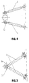
- the vehicle wheel R which has a wheel axle 13 is held on an axle support 7 and guided with the aid of a spring cylinder and with the aid of control arms 3.
- the spring cylinder comprises an inner tube 1a and an outer tube 1b.
- the inner and outer tubes are slidable and rotatable relative to each other.
- a hydraulic oil supply extends through the center of the spring cylinder 6 ', which consists essentially of two concentric tubes which are sealed so that the two tubes can move in the longitudinal direction to one another and can rotate relative to one another. Furthermore, the hydraulic oil duct 6 'is provided with oil compensation devices (not shown) in order to compensate for volume changes as a result of spring movements.
- the hydraulic bushing 6 ' is connected to a hydraulic oil supply 6.
- the hydraulic oil bushing 6 ′ is in flow connection with a hydraulic motor 2, which represents an independent wheel drive and is received in the axle support 7 together with a manual transmission 4.
- the axle support 7 and thus also the hydraulic motor 2 and the manual transmission 4 are arranged in the hub area of the vehicle wheel R, i.e. in the area of the wheel axle or the wheel center of rotation 13.
- the lower end of the spring cylinder outer tube 1b is fixedly connected to the upper side of the axle support 7, while the upper end of the spring cylinder inner tube 1a is supported in an elastic bearing 8 in a spatially movable or three-dimensional manner.
- This elastic bearing 8 which is preferably designed as a rubber bearing, is fastened to a cross member 14 which extends essentially parallel to the wheel axis 13.
- This cross member 14 is held by a carrier 9, with the upper end of which the cross member is connected.
- the lower end of the carrier 9 is welded to the vehicle frame 12.
- the vehicle frame 12 is arranged so deep that it is essentially at the level of the wheel axle 13, ie essentially at the level of the hydraulic motor 2.
- the two wishbones 3 are articulated with their ends 3a facing the vehicle wheel on the underside of the axle support 7, while the opposite ends of the wishbones 3 are articulated on the underside of the vehicle frame 12.
- the ends 3a of the two links are articulated at a distance from one another. According to the embodiment shown in FIG. 3, however, the ends 3a of the two wishbones 3 are connected to one another.
- the wishbones 3 are used to absorb the acceleration forces and braking forces occurring in vehicle operation as well as the cornering forces and the resulting supporting forces from the contact force (when using the device according to the invention for crane vehicles).
- all that remains of the carrier 9 is the contact force and the remaining forces of braking and accelerating. Consequently, the construction 9 relieves the load of all the forces which are absorbed by the cross beams. This in turn has the consequence that the carrier 9 can be designed in a structurally quite simple manner, which leads to a weight saving.
- a steering lever 10 is attached to the spring cylinder outer tube 1b, which is fixedly connected to the axle bracket 7.
- a tie rod 5 is mounted spatially, that is to say three-dimensionally, with the aid of a first ball head 11.
- a second ball head 11 ' is provided at the other end of the tie rod 5 and connected to a device (not shown) for steering the vehicle wheel R.
- the hydraulic oil bushing 6 ' In the area of the spring cylinder 1a, 1b, the hydraulic oil bushing 6 'consists of a first tube section provided centrally in the spring cylinder inner tube 1a and a second tube section provided centrally in the spring cylinder outer tube 1b. These two sections of the oil feedthrough 6 'have different diameters, so that the two pipe sections are overlapping one another over a certain length. At the same time, the two pipe sections are sealed against each other, so that relative movements of the (resilient) spring cylinder outer pipe 1b relative to the spring cylinder inner pipe 1a (belonging to the sprung mass) can be carried out by the two pipe sections of the oil duct 6 '. As already mentioned, expansion tanks or the like, not shown, are provided in order to compensate for volume changes occurring as a result of suspension movements.
Landscapes
- Engineering & Computer Science (AREA)
- Mechanical Engineering (AREA)
- Chemical & Material Sciences (AREA)
- Combustion & Propulsion (AREA)
- Transportation (AREA)
- Vehicle Body Suspensions (AREA)
- Steering-Linkage Mechanisms And Four-Wheel Steering (AREA)
- Steering Controls (AREA)
- Platform Screen Doors And Railroad Systems (AREA)
- Arrangement Or Mounting Of Propulsion Units For Vehicles (AREA)
Applications Claiming Priority (2)
| Application Number | Priority Date | Filing Date | Title |
|---|---|---|---|
| DE9305633U | 1993-04-15 | ||
| DE9305633U DE9305633U1 (de) | 1993-04-15 | 1993-04-15 | Vorrichtung zum Antreiben, Führen und Lenken eines Fahrzeugrades |
Publications (2)
| Publication Number | Publication Date |
|---|---|
| EP0620132A1 true EP0620132A1 (fr) | 1994-10-19 |
| EP0620132B1 EP0620132B1 (fr) | 1998-07-29 |
Family
ID=6892013
Family Applications (1)
| Application Number | Title | Priority Date | Filing Date |
|---|---|---|---|
| EP94105501A Expired - Lifetime EP0620132B1 (fr) | 1993-04-15 | 1994-04-08 | Installation pour entraíner, guider et diriger une roue de véhicule |
Country Status (4)
| Country | Link |
|---|---|
| US (1) | US5542492A (fr) |
| EP (1) | EP0620132B1 (fr) |
| AT (1) | ATE168942T1 (fr) |
| DE (2) | DE9305633U1 (fr) |
Cited By (6)
| Publication number | Priority date | Publication date | Assignee | Title |
|---|---|---|---|---|
| RU2139796C1 (ru) * | 1999-03-18 | 1999-10-20 | Каменский Виктор Евгеньевич | Быстродействующая подвеска колеса гоночного автомобиля |
| WO2007118845A1 (fr) * | 2006-04-13 | 2007-10-25 | Peter Seikel | Transmission pour une roue individuelle |
| WO2013150099A3 (fr) * | 2012-04-05 | 2013-12-12 | Goldhofer Ag | Remorques pour poids lourds dotées d'une suspension indépendante macpherson |
| FR3028458A1 (fr) * | 2014-11-18 | 2016-05-20 | Laurent Eugene Albert | Procede pour alimenter en fluide hydraulique un moteur hydraulique de roue motrice, suspension a verin s'y rapportant et vehicule ainsi equipe |
| WO2019120734A1 (fr) * | 2017-12-22 | 2019-06-27 | Manitowoc Crane Group France Sas | Essieu de châssis de grue mobile |
| WO2021143978A1 (fr) * | 2020-01-16 | 2021-07-22 | Schaeffler Technologies AG & Co. KG | Module de roue et jambe de force pour un véhicule à moteur |
Families Citing this family (10)
| Publication number | Priority date | Publication date | Assignee | Title |
|---|---|---|---|---|
| DE4341034C2 (de) * | 1993-12-02 | 1997-03-13 | Glaeser Hydraulik Gmbh | Hydraulikleitung-Verbindung |
| US7533747B2 (en) * | 2000-01-26 | 2009-05-19 | E-Traction Europe B.V. | Wheel provided with driving means |
| NL1014182C2 (nl) * | 2000-01-26 | 2001-07-27 | Special Products For Industry | Wiel voorzien van aandrijfmiddelen. |
| BE1013399A3 (nl) * | 2000-04-20 | 2001-12-04 | Hool Nv Van | Verbeterde voorwielophanging voor bussen en dergelijke. |
| ATE391043T1 (de) * | 2003-12-11 | 2008-04-15 | Kanzaki Kokyukoki Mfg Co Ltd | Hydraulisches achsgetriebe und fahrzeug mit solchem achsgetriebe |
| DE102004014555A1 (de) * | 2004-03-25 | 2005-12-22 | Zf Friedrichshafen Ag | Radaufhängung für ein lenkbares Fahrzeugrad |
| CN2889765Y (zh) * | 2006-03-03 | 2007-04-18 | 广州市番禺华南摩托企业集团有限公司 | 带有球头转向节的前摇架 |
| EP2146857A1 (fr) * | 2007-05-10 | 2010-01-27 | Aarhus Universitet | Roue motrice et directrice omnirotationnelle |
| JP6369166B2 (ja) * | 2014-06-27 | 2018-08-08 | 日産自動車株式会社 | 車両用サスペンション装置 |
| WO2015198679A1 (fr) * | 2014-06-27 | 2015-12-30 | 日産自動車株式会社 | Appareil d'alimentation électrique non suspendu pour véhicule à moteur-roue |
Citations (4)
| Publication number | Priority date | Publication date | Assignee | Title |
|---|---|---|---|---|
| US3581682A (en) * | 1969-02-24 | 1971-06-01 | Aerospace America Inc | Driving apparatus for a wheeled vehicle |
| US3997018A (en) * | 1972-01-14 | 1976-12-14 | Hyster Company | Drive wheel assembly with high flotation tire for compaction vehicles |
| US5150763A (en) * | 1991-04-24 | 1992-09-29 | Aisin Aw Co., Ltd. | Wiring and piping arrangement for a vehicle motor |
| WO1993005969A1 (fr) * | 1991-09-21 | 1993-04-01 | Krupp Industrietechnik Gesellschaft Mit Beschränkter Haftung | Jambe de suspension pour commande hydraulique des roues |
Family Cites Families (7)
| Publication number | Priority date | Publication date | Assignee | Title |
|---|---|---|---|---|
| DE1857359U (de) * | 1958-12-03 | 1962-08-23 | Ehrenreich & Cie A | Vorrichtung zur abstuetzung der radgelenke gelenkter fahrzeugraeder. |
| DE1120290B (de) * | 1959-01-14 | 1961-12-21 | Max Adolf Mueller Dipl Ing | Radaufhaengung fuer Fahrzeuge, insbesondere Schwerlastfahrzeuge |
| US3161246A (en) * | 1962-07-16 | 1964-12-15 | Product Dev Corp | Driving and suspension system for amphibious vehicle |
| DE2623757A1 (de) * | 1976-05-26 | 1977-12-01 | Trw Inc | Antriebseinheit |
| US4162713A (en) * | 1978-04-03 | 1979-07-31 | Otis Engineering Corporation | Planetary transmission with hydraulic engagement and disengagement |
| FR2432948A1 (fr) * | 1978-07-26 | 1980-03-07 | Iao Industrie Riunite Spa | Montant pour suspensions du type mac pherson pour vehicules automobiles |
| JP3367614B2 (ja) * | 1991-10-17 | 2003-01-14 | 株式会社小松製作所 | ダンプトラックの操舵輪油圧駆動装置 |
-
1993
- 1993-04-15 DE DE9305633U patent/DE9305633U1/de not_active Expired - Lifetime
-
1994
- 1994-04-08 AT AT94105501T patent/ATE168942T1/de not_active IP Right Cessation
- 1994-04-08 DE DE59406529T patent/DE59406529D1/de not_active Expired - Fee Related
- 1994-04-08 EP EP94105501A patent/EP0620132B1/fr not_active Expired - Lifetime
- 1994-04-12 US US08/226,482 patent/US5542492A/en not_active Expired - Fee Related
Patent Citations (4)
| Publication number | Priority date | Publication date | Assignee | Title |
|---|---|---|---|---|
| US3581682A (en) * | 1969-02-24 | 1971-06-01 | Aerospace America Inc | Driving apparatus for a wheeled vehicle |
| US3997018A (en) * | 1972-01-14 | 1976-12-14 | Hyster Company | Drive wheel assembly with high flotation tire for compaction vehicles |
| US5150763A (en) * | 1991-04-24 | 1992-09-29 | Aisin Aw Co., Ltd. | Wiring and piping arrangement for a vehicle motor |
| WO1993005969A1 (fr) * | 1991-09-21 | 1993-04-01 | Krupp Industrietechnik Gesellschaft Mit Beschränkter Haftung | Jambe de suspension pour commande hydraulique des roues |
Cited By (14)
| Publication number | Priority date | Publication date | Assignee | Title |
|---|---|---|---|---|
| RU2139796C1 (ru) * | 1999-03-18 | 1999-10-20 | Каменский Виктор Евгеньевич | Быстродействующая подвеска колеса гоночного автомобиля |
| WO2007118845A1 (fr) * | 2006-04-13 | 2007-10-25 | Peter Seikel | Transmission pour une roue individuelle |
| EA015050B1 (ru) * | 2006-04-13 | 2011-04-29 | Петер Зайкель | Индивидуальный привод колеса |
| WO2013150099A3 (fr) * | 2012-04-05 | 2013-12-12 | Goldhofer Ag | Remorques pour poids lourds dotées d'une suspension indépendante macpherson |
| US9919573B2 (en) | 2012-04-05 | 2018-03-20 | Goldhofer Ag | Heavy-duty trailer with MacPherson independent wheel suspension |
| RU2623366C2 (ru) * | 2012-04-05 | 2017-06-23 | Гольдхофер Аг | Большегрузный прицеп с независимой подвеской колёс мак-ферсона |
| WO2016078917A1 (fr) * | 2014-11-18 | 2016-05-26 | Albert Laurent Eugène | Procede pour alimenter en fluide hydraulique un moteur hydraulique de roue motrice, suspension a verin s'y rapportant et vehicule ainsi equipe |
| FR3028459A1 (fr) * | 2014-11-18 | 2016-05-20 | Laurent Eugene Albert | Procede d'alimentation d'un moteur hydraulique et suspension a verin comprenant une chambre de compensation s'y rapportant |
| FR3028458A1 (fr) * | 2014-11-18 | 2016-05-20 | Laurent Eugene Albert | Procede pour alimenter en fluide hydraulique un moteur hydraulique de roue motrice, suspension a verin s'y rapportant et vehicule ainsi equipe |
| US10421331B2 (en) | 2014-11-18 | 2019-09-24 | Laurent Eugène ALBERT | Method of supplying a hydraulic motor for a drive wheel with hydraulic fluid, associated cylinder-type suspension system and vehicle equipped therewith |
| WO2019120734A1 (fr) * | 2017-12-22 | 2019-06-27 | Manitowoc Crane Group France Sas | Essieu de châssis de grue mobile |
| US11919359B2 (en) | 2017-12-22 | 2024-03-05 | Manitowoc Crane Group France Sas | Mobile crane travel gear axle |
| DE102017131165B4 (de) | 2017-12-22 | 2024-04-11 | Manitowoc Crane Group France Sas | Mobilkran-Fahrwerk |
| WO2021143978A1 (fr) * | 2020-01-16 | 2021-07-22 | Schaeffler Technologies AG & Co. KG | Module de roue et jambe de force pour un véhicule à moteur |
Also Published As
| Publication number | Publication date |
|---|---|
| EP0620132B1 (fr) | 1998-07-29 |
| DE59406529D1 (de) | 1998-09-03 |
| DE9305633U1 (de) | 1993-06-17 |
| ATE168942T1 (de) | 1998-08-15 |
| US5542492A (en) | 1996-08-06 |
Similar Documents
| Publication | Publication Date | Title |
|---|---|---|
| EP0620132B1 (fr) | Installation pour entraíner, guider et diriger une roue de véhicule | |
| DE69934671T2 (de) | Verstellbare fahrzeugaufhängung | |
| EP0278095B1 (fr) | Suspension pour roues orientables de véhicules à moteur, en particulier pour roues arrières | |
| EP0656270A1 (fr) | Suspension de roue | |
| EP0141093A2 (fr) | Suspension pour des roues avant dirigeables de véhicules automobiles | |
| EP0464412B1 (fr) | Suspension pneumatique à bras longitudinaux | |
| DE3743203C2 (fr) | ||
| DE3535589C1 (de) | Radaufhaengung fuer absenkbare Fahrzeugaufbauten,insbesondere fuer Anhaenger,frontangetriebene LKW(Bus-Kombi),Wohnmobile | |
| EP0247389B1 (fr) | Balancier de guidage de roues ferroviaires à entraînement extérieur et pouvant osciller horizontalement | |
| DE3807273C1 (fr) | ||
| DE102010060274A1 (de) | Achsaggregate | |
| DE3809995A1 (de) | Hintere aufhaengungseinrichtung fuer motorfahrzeuge | |
| DE9308654U1 (de) | Doppelquerlenker-Vorrichtung zum Führen, Antreiben und Lenken eines Fahrzeugrades | |
| DE3049198C2 (fr) | ||
| DE102010060273A1 (de) | Gewichtsoptimierte Lastkraftfahrzeuge | |
| DE112023000136T5 (de) | Struktur zum fahren eines vierrädrigen fahrzeugs in mehrere richtungen und zum dessen lenken | |
| WO1997023375A2 (fr) | Bogie de vehicule ferroviaire a deux essieux | |
| DE102020123524B4 (de) | Radmodul für ein Kraftfahrzeug | |
| DE4024825C1 (en) | Support legs for semi-trailer - has inner tube sections with supports for feet which pivot | |
| DE3234475C2 (fr) | ||
| DD152513A5 (de) | Achsanlenkung fuer eine angetriebene achse eines strassenfahrzeugs | |
| DE102020123401A1 (de) | Radmodul für ein Fahrzeug, Fahrzeug mit dem Radmodul und Verfahren zur Erweiterung eines Lenkwinkels | |
| DE1004497B (de) | Als Pendelachse ausgebildete Hinterachse fuer Motorfahrzeuge | |
| DE102021104230B4 (de) | Radmodul | |
| EP0619788A1 (fr) | Longeron de chassis. |
Legal Events
| Date | Code | Title | Description |
|---|---|---|---|
| PUAI | Public reference made under article 153(3) epc to a published international application that has entered the european phase |
Free format text: ORIGINAL CODE: 0009012 |
|
| AK | Designated contracting states |
Kind code of ref document: A1 Designated state(s): AT BE CH DE DK ES FR GB IT LI LU MC NL PT SE |
|
| 17P | Request for examination filed |
Effective date: 19941228 |
|
| 17Q | First examination report despatched |
Effective date: 19961111 |
|
| GRAG | Despatch of communication of intention to grant |
Free format text: ORIGINAL CODE: EPIDOS AGRA |
|
| RAP1 | Party data changed (applicant data changed or rights of an application transferred) |
Owner name: KASPAR, ERNST Owner name: LUTZ, FRANZ Owner name: COMPACT TRUCK AG |
|
| GRAG | Despatch of communication of intention to grant |
Free format text: ORIGINAL CODE: EPIDOS AGRA |
|
| GRAH | Despatch of communication of intention to grant a patent |
Free format text: ORIGINAL CODE: EPIDOS IGRA |
|
| GRAH | Despatch of communication of intention to grant a patent |
Free format text: ORIGINAL CODE: EPIDOS IGRA |
|
| GRAA | (expected) grant |
Free format text: ORIGINAL CODE: 0009210 |
|
| AK | Designated contracting states |
Kind code of ref document: B1 Designated state(s): AT BE CH DE DK ES FR GB IT LI LU MC NL PT SE |
|
| PG25 | Lapsed in a contracting state [announced via postgrant information from national office to epo] |
Ref country code: NL Free format text: LAPSE BECAUSE OF FAILURE TO SUBMIT A TRANSLATION OF THE DESCRIPTION OR TO PAY THE FEE WITHIN THE PRESCRIBED TIME-LIMIT Effective date: 19980729 Ref country code: IT Free format text: LAPSE BECAUSE OF FAILURE TO SUBMIT A TRANSLATION OF THE DESCRIPTION OR TO PAY THE FEE WITHIN THE PRESCRIBED TIME-LIMIT;WARNING: LAPSES OF ITALIAN PATENTS WITH EFFECTIVE DATE BEFORE 2007 MAY HAVE OCCURRED AT ANY TIME BEFORE 2007. THE CORRECT EFFECTIVE DATE MAY BE DIFFERENT FROM THE ONE RECORDED. Effective date: 19980729 Ref country code: GB Free format text: LAPSE BECAUSE OF FAILURE TO SUBMIT A TRANSLATION OF THE DESCRIPTION OR TO PAY THE FEE WITHIN THE PRESCRIBED TIME-LIMIT Effective date: 19980729 Ref country code: FR Free format text: LAPSE BECAUSE OF FAILURE TO SUBMIT A TRANSLATION OF THE DESCRIPTION OR TO PAY THE FEE WITHIN THE PRESCRIBED TIME-LIMIT Effective date: 19980729 Ref country code: ES Free format text: THE PATENT HAS BEEN ANNULLED BY A DECISION OF A NATIONAL AUTHORITY Effective date: 19980729 |
|
| REF | Corresponds to: |
Ref document number: 168942 Country of ref document: AT Date of ref document: 19980815 Kind code of ref document: T |
|
| REG | Reference to a national code |
Ref country code: CH Ref legal event code: EP |
|
| REF | Corresponds to: |
Ref document number: 59406529 Country of ref document: DE Date of ref document: 19980903 |
|
| PG25 | Lapsed in a contracting state [announced via postgrant information from national office to epo] |
Ref country code: SE Free format text: LAPSE BECAUSE OF FAILURE TO SUBMIT A TRANSLATION OF THE DESCRIPTION OR TO PAY THE FEE WITHIN THE PRESCRIBED TIME-LIMIT Effective date: 19981029 Ref country code: PT Free format text: LAPSE BECAUSE OF FAILURE TO SUBMIT A TRANSLATION OF THE DESCRIPTION OR TO PAY THE FEE WITHIN THE PRESCRIBED TIME-LIMIT Effective date: 19981029 Ref country code: DK Free format text: LAPSE BECAUSE OF FAILURE TO SUBMIT A TRANSLATION OF THE DESCRIPTION OR TO PAY THE FEE WITHIN THE PRESCRIBED TIME-LIMIT Effective date: 19981029 |
|
| EN | Fr: translation not filed | ||
| NLV1 | Nl: lapsed or annulled due to failure to fulfill the requirements of art. 29p and 29m of the patents act | ||
| GBV | Gb: ep patent (uk) treated as always having been void in accordance with gb section 77(7)/1977 [no translation filed] |
Effective date: 19980729 |
|
| PG25 | Lapsed in a contracting state [announced via postgrant information from national office to epo] |
Ref country code: LU Free format text: LAPSE BECAUSE OF NON-PAYMENT OF DUE FEES Effective date: 19990408 Ref country code: AT Free format text: LAPSE BECAUSE OF NON-PAYMENT OF DUE FEES Effective date: 19990408 |
|
| PG25 | Lapsed in a contracting state [announced via postgrant information from national office to epo] |
Ref country code: LI Free format text: LAPSE BECAUSE OF NON-PAYMENT OF DUE FEES Effective date: 19990430 Ref country code: CH Free format text: LAPSE BECAUSE OF NON-PAYMENT OF DUE FEES Effective date: 19990430 Ref country code: BE Free format text: LAPSE BECAUSE OF NON-PAYMENT OF DUE FEES Effective date: 19990430 |
|
| PLBE | No opposition filed within time limit |
Free format text: ORIGINAL CODE: 0009261 |
|
| STAA | Information on the status of an ep patent application or granted ep patent |
Free format text: STATUS: NO OPPOSITION FILED WITHIN TIME LIMIT |
|
| 26N | No opposition filed | ||
| BERE | Be: lapsed |
Owner name: KASPAR ERNST Effective date: 19990430 Owner name: LUTZ FRANZ Effective date: 19990430 Owner name: COMPACT TRUCK A.G. Effective date: 19990430 |
|
| PG25 | Lapsed in a contracting state [announced via postgrant information from national office to epo] |
Ref country code: MC Free format text: LAPSE BECAUSE OF NON-PAYMENT OF DUE FEES Effective date: 19991031 |
|
| REG | Reference to a national code |
Ref country code: CH Ref legal event code: PL |
|
| PGFP | Annual fee paid to national office [announced via postgrant information from national office to epo] |
Ref country code: DE Payment date: 20030528 Year of fee payment: 10 |
|
| PG25 | Lapsed in a contracting state [announced via postgrant information from national office to epo] |
Ref country code: DE Free format text: LAPSE BECAUSE OF NON-PAYMENT OF DUE FEES Effective date: 20041103 |