EP0620148A2 - Vehicle loading surface structure with a support tube - Google Patents
Vehicle loading surface structure with a support tube Download PDFInfo
- Publication number
- EP0620148A2 EP0620148A2 EP94105303A EP94105303A EP0620148A2 EP 0620148 A2 EP0620148 A2 EP 0620148A2 EP 94105303 A EP94105303 A EP 94105303A EP 94105303 A EP94105303 A EP 94105303A EP 0620148 A2 EP0620148 A2 EP 0620148A2
- Authority
- EP
- European Patent Office
- Prior art keywords
- profile
- support
- pipe section
- structure according
- guide rail
- Prior art date
- Legal status (The legal status is an assumption and is not a legal conclusion. Google has not performed a legal analysis and makes no representation as to the accuracy of the status listed.)
- Granted
Links
Images


Classifications
-
- B—PERFORMING OPERATIONS; TRANSPORTING
- B60—VEHICLES IN GENERAL
- B60P—VEHICLES ADAPTED FOR LOAD TRANSPORTATION OR TO TRANSPORT, TO CARRY, OR TO COMPRISE SPECIAL LOADS OR OBJECTS
- B60P7/00—Securing or covering of load on vehicles
- B60P7/06—Securing of load
- B60P7/135—Securing or supporting by load bracing means
- B60P7/15—Securing or supporting by load bracing means the load bracing means comprising a movable bar
-
- B—PERFORMING OPERATIONS; TRANSPORTING
- B62—LAND VEHICLES FOR TRAVELLING OTHERWISE THAN ON RAILS
- B62D—MOTOR VEHICLES; TRAILERS
- B62D33/00—Superstructures for load-carrying vehicles
- B62D33/04—Enclosed load compartments ; Frameworks for movable panels, tarpaulins or side curtains
- B62D33/042—Enclosed load compartments ; Frameworks for movable panels, tarpaulins or side curtains divided into compartments
Definitions
- the invention relates to a structure for the loading area of a vehicle with at least one pair of guide rails provided approximately horizontally on side walls at a distance from the loading area, to the end connecting elements of a support tube or the like running between them in the operating position.
- Support profile can be connected, the length of the support profile corresponds approximately to the distance between the two guide rails from each other.
- clothes rails which can be horizontally displaced between guide rails or, for example, from EP-PS 0 159 394 horizontal lashing rails in a truck body.
- the support profile is connected at a distance from a profile end to at least one strand-like handlebar by a joint and the handlebar is fixed at the other end by means of a further joint - preferably connected to the guide rail - with the support profile around its joint and the handlebar around the other Joint can be folded out of the operating position into a rest position.
- the further joint should be able to be fixed in a clamped manner on a profile, preferably C-shaped cross section, which partially surrounds the guide rail and is fixable on it.
- the support profile can form a support beam as a support tube with at least one similar support tube connected in parallel, and the strand-like link can run as a pipe section between the support tube pair.
- the support profile is a box profile with a laterally projecting upper flange, on the profile side walls of which a strand-like link is articulated.
- a cross bolt protrudes from the handlebar or the tube piece at its end remote from the clamping profile, which is guided as a hinge axis in an axial elongated hole of the support profile or the support tube (s) and can be displaced by this mounting relative to the support profile or the like . It is possible to choose whether the elongated hole or the transverse bolt is assigned to the support profile from this pair of elongated holes / transverse bolts.
- the support profile or the support tubes as the connecting element has / have at least one hook profile, which is to be inserted into an upwardly directed longitudinal groove of the guide rail and removed from it by lifting it.
- an axially movable bolt is provided on that hook profile and / or the C-shaped profile of the pipe section or handlebar, the free end of which can be inserted under spring pressure into a bore or recess in the guide rail.
- the pipe section In the horizontal operating position, the pipe section is fixed parallel to these at the two hinge axes and at least one stop web extending over it between the support pipes.
- the stop bar should be provided outside a swiveling circle of the free end of the pipe section around the cross bolt when the latter is supported on the end of the elongated hole of the pipe section close to the stop bar.
- the pipe section or the handlebar can be folded through 180 ° from the operating position between the support pipes or to the support profile and its free end can be placed against the stop web or the upper flange of the box profile.
- the cross bolt is mounted on the end of the elongated hole of the pipe section remote from the stop web.
- an axially displaceable or a pivotable securing bolt is pressed into a bore of the guide rail by an energy accumulator.
- the safety bolt penetrates the C-shaped profile of the pipe section or handlebar, which is flanked on both sides by hook profiles.
- the support profile that can be clamped between the guide rails consists of a support unit with a hinged handlebar. That support profile, also called support beam, is fastened and locked in the operating position transversely to the longitudinal axis of the vehicle and horizontally on the guide rails or is folded against one of the side walls in the rest position and can also be locked in this way. After the locks have been released, this support beam can be moved along the guide rails in the longitudinal direction of the vehicle and / or rotated about a joint unit; it is guided by means of the handlebar, which is connected both to the joint unit and to the support unit via a further joint.
- the supporting beam lies in the operating position on one side of the joint unit and on the opposite side of the guide rail, whereby profiles create a positive connection between the guide rails and the supporting beams, which prevent them from moving transversely to the vehicle's longitudinal axis.
- the joint unit is positively attached to a guide rail as part of the support unit by means of a profile, so that vertical displacements are also prevented.
- locking mechanisms on both sides lock the support beam against shifting in the longitudinal direction of the vehicle.
- tandem bar that is safe and highly resilient in its horizontal operating position, which can be folded into its vertical rest position without any effort.
- the loading area 10 of, for example, about 12 m (length a) of a vehicle (not shown further) is flanked by side walls 12 of a box body 14 with a clear internal height h of 250 cm, the roof 16 of which can be seen in FIG. 2 and the box end wall is designated here by 18 .
- the interior width b also measures approximately 250 cm.
- each guide rail 22 has, as shown in particular in FIG. 5, a longitudinal groove 25 of vertical cross section on both sides of a hollow central strip 23, the main surface of which is provided with a gallery of bores 24; both longitudinal grooves 25 are directed in opposite directions in cross-section and delimited by a base strip 26 fixed to the side wall 12.
- Double-deck beam 20 In the operating position of the double-deck beam 20, a hook profile 28 engages in the upper longitudinal groove 25 of the left guide rail 22 in FIG Double-deck beam 20 is fixed and is penetrated by an axial bolt 32 - loaded by a helical spring 31; this sits in one of the bores 24 of the guide rail 22.
- the construction of the double-decker beam 20 of FIG. 7 is composed of two support tubes 34, which run parallel to one another at a distance i and are each connected at one end to the plate-like common hook profile 28 with a telescopic pin 30.
- the mentioned axial bolt 32 with the helical spring 31 surrounding it is located between the two support tubes 34, and its extension rod 32a ends in a towing eye 33.
- the axial bolt 32 - which lies in the central axis M of the double-decker or tandem beam 20 - penetrates one Cross plate 36, which connects the two support tubes 34 to one another.
- the coil spring 31 of the axial bolt 32 is supported at one end against its collar 31a and at the other end against the cross plate 36.
- a spring-loaded axial bolt 32 is also provided at the other end of the double-decker beam 20, which is on the right in the drawing, but is supported here in a pipe section 42 attached between support pipes 34; the latter is articulated at a distance n from the adjacent hook profile 28r by a transverse bolt 44 which is seated at both ends in the support tubes 34 and passes through an axial elongated hole 43 of the tube piece 42, this distance n measuring approximately a quarter of the abovementioned internal width b.
- the pipe section 42 is connected via a hinge 46 to a C-profile 48, the vertical cross section of which, according to FIG. 10, forms a channel section on both sides of the axial bolt 32.
- Each of these can be inserted into a longitudinal groove 25 of the guide rail 22, i.e. the C-profile 48 is held in a clamped manner on the guide rail 22.
- a hook profile 28r is provided on both sides of the C-profile 48.
- the left end of the beam is lowered, the double-decker beam 20 rotating about the cross bolt 44; the right hook profiles 28r leave the right guide rail 22 upwards and are raised towards the roof.
- the pipe section 42 articulated at both ends forms a link between the right guide rail 22 and the double-decker beam 20 approaching the right side wall 12; this rotates around the cross bolt 44, while the wall-side end of the pipe section 42 is pivoted about the pivot bolt 47.
- the double-decker beam 20 lies approximately along the entire length of the side wall 12, and the pipe section 42 then runs between the support tubes 34 from the cross bolt 44 to the guide rail 22, on which it is held by the C-profile 48 becomes.
- the cross bolt 44 slides in the elongated hole 43 - and thus the double-decker beam 20 - by a dimension q, the stop bar 50 near the joint reaching the vertical pipe section 42 and thus fixing the system 34/42 in the vertical rest position.
- this stop bar 50 near the joint which is provided directly next to the circular swivel contour K of the adjacent pipe end, is shown outside of this rest or fixing position, in FIG. 11 in the latter.
- an extruded tandem profile 52 is used as the main element of the double-deck beam 20a.
- This tandem profile 52 is a box profile with a height f of approximately 90 mm with a top flange 54 of length 140 of approximately 140 mm with a symmetrical projection on both sides of the profile side walls 53 with a profiled surface 55.
- the telescopic pin 30 is supported here with an insertion end 29 in the box space 58 of the tandem profile 52.
- an elongated hole pair 38a is provided for the crossbar 40 seated here in the tandem profile 52.
- tandem profile 52 can be adapted to a limited extent.
Landscapes
- Engineering & Computer Science (AREA)
- Transportation (AREA)
- Mechanical Engineering (AREA)
- Chemical & Material Sciences (AREA)
- Combustion & Propulsion (AREA)
- Body Structure For Vehicles (AREA)
- Fittings On The Vehicle Exterior For Carrying Loads, And Devices For Holding Or Mounting Articles (AREA)
Abstract
Bei einem Aufbau (14) für die Ladefläche (10) eines Fahrzeuges mit wenigstens einem an Seitenwänden (12) in mittlerem Abstand (H1) zur Ladefläche 10) etwa horizontal vorgesehenen Paar von Führungschienen (22), an die endwärtige Verbindugsorgane eies zwischen ihnen in Betriebsstellung verlaufenden Tragrohres od. dgl. Tragprofils (20) anschließbar sind, ist in Abstand zu einer Führungsschiene (22) das Tragprofil (20) mit einem strangartigen Lenker (42) durch ein Gelenk (449 verbunden und der Lenker (42) andernends mittels eines weiteren Gelenkes (42) an die Führungsschiene (22) angeschlossen, wobei das Tragprofil um sein Gelenk (44) und der Lenker (42) um das weitere Gelenk 47) in seine Ruhelage klappbar sind. Letzteres soll an einem die Führungsschiene (22) teilweise umfassenden und an ihr fixierbar vorgesehenen Profil C-förmiogen Querschnittes festliegen.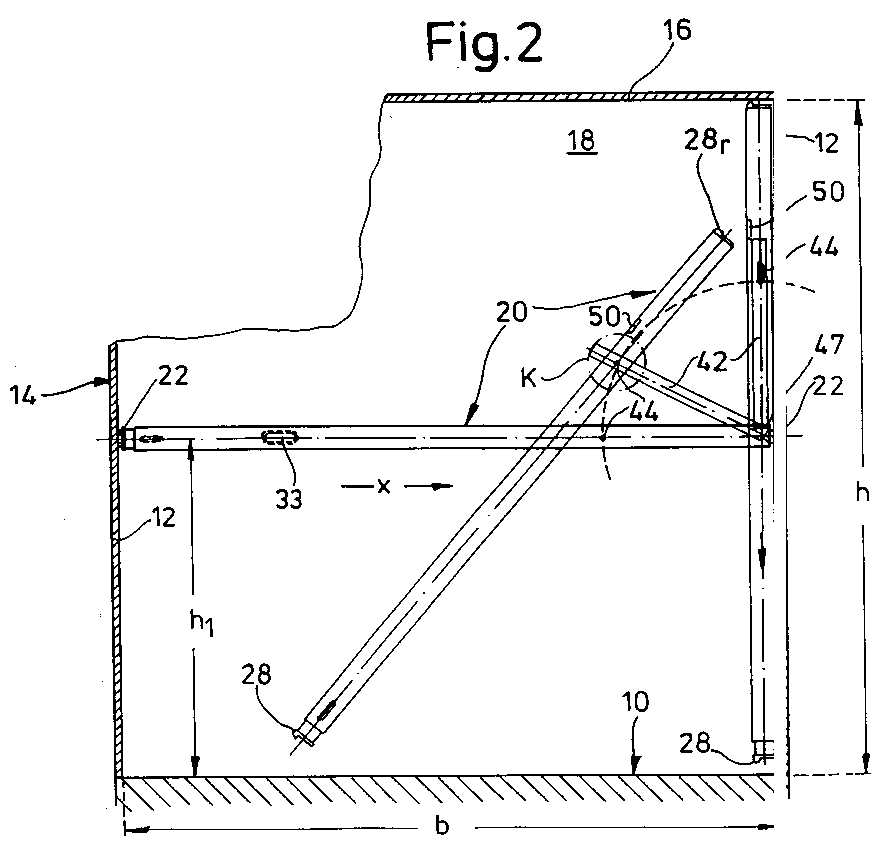
Description
Die Erfindung betrifft einen Aufbau für die Ladefläche eines Fahrzeuges mit wenigstens einem an Seitenwänden in Abstand zur Ladefläche etwa horizontal vorgesehenen Paar von Führungsschienen, an die endwärtige Verbindungsorgane eines zwischen ihnen in Betriebsstellung verlaufenden Tragrohres od.dgl. Tragprofiles anschließbar sind, wobei die Länge des Tragprofiles etwa dem Abstand der beiden Führungsschienen voneinander entspricht.The invention relates to a structure for the loading area of a vehicle with at least one pair of guide rails provided approximately horizontally on side walls at a distance from the loading area, to the end connecting elements of a support tube or the like running between them in the operating position. Support profile can be connected, the length of the support profile corresponds approximately to the distance between the two guide rails from each other.
Bekannt sind beispielsweise zwischen Führungsschienen horizontal verschiebbare Kleiderstangen oder etwa aus der EP-PS 0 159 394 horizontale Zurrschienen in einem Lastwagenaufbau.Known, for example, are clothes rails which can be horizontally displaced between guide rails or, for example, from EP-PS 0 159 394 horizontal lashing rails in a truck body.
In Kenntnis dieses Standes der Technik hat sich der Erfinder das Ziel gesetzt, eingangs beschriebene Aufbauten mit problemlos demontierbaren Tragprofilen für einen Zwischenboden od.dgl. auszustatten.Knowing this state of the art, the inventor has set himself the goal of building structures described at the beginning with easily removable support profiles for an intermediate floor or the like. equip.
Zur Lösung dieser Aufgabe führt die Lehre des unabhängigen Anspruches; die Unteransprüche erfassen günstige Weiterbildungen.The teaching of the independent claim leads to the solution of this task; the subclaims cover favorable further training.
Erfindungsgemäß wird das Tragprofil in Abstand zu einem Profilende mit wenigstens einem strangartigen Lenker durch ein Gelenk verbunden und der Lenker andernends mittels eines weiteren Gelenkes ortsfest -- bevorzugt an die Führungsschiene angeschlossen -- gelagert, wobei das Tragprofil um sein Gelenk und der Lenker um das weitere Gelenk aus der Betriebsstellung in eine Ruhelage klappbar sind.According to the invention, the support profile is connected at a distance from a profile end to at least one strand-like handlebar by a joint and the handlebar is fixed at the other end by means of a further joint - preferably connected to the guide rail - with the support profile around its joint and the handlebar around the other Joint can be folded out of the operating position into a rest position.
Nach einem weiteren Merkmal der Erfindung soll das weitere Gelenk anderseits an einem die Führungsschiene teilweise umfassenden und an ihr fixierbar vorgesehenen Profil -- bevorzugt C-förmigen Querschnittes -- klammernd festlegbar sein.According to a further feature of the invention, on the other hand, the further joint should be able to be fixed in a clamped manner on a profile, preferably C-shaped cross section, which partially surrounds the guide rail and is fixable on it.
Das Tragprofil kann erfindungsgemäß als Tragrohr mit wenigstens einem parallel angeschlossenen gleichartigen Tragrohr einen Tragbalken bilden und der strangartige Lenker als Rohrstück zwischen dem Tragrohrpaar verlaufen. Bei einer weiteren bevorzugten Ausführungsform ist das Tragprofil ein Kastenprofil mit seitlich überkragendem Obergurt ausgebildet, an dessen Profilseitenwänden jeweils ein strangartiger Lenker angelenkt ist.According to the invention, the support profile can form a support beam as a support tube with at least one similar support tube connected in parallel, and the strand-like link can run as a pipe section between the support tube pair. In a further preferred embodiment, the support profile is a box profile with a laterally projecting upper flange, on the profile side walls of which a strand-like link is articulated.
Vorteilhafterweise ragt von dem Lenker oder dem Rohrstück an seinem dem klammernden Profil fernen Ende ein Querbolzen ab, der als Gelenkachse in einem axialen Langloch des Tragprofils bzw. der/des Tragrohre/s geführt und durch diese Lagerung relativ zum Tragprofil od. dgl. verschiebbar ist. Es ist wählbar, ob von dieser Paarung Langloch/Querbolzen das Langloch oder der Querbolzen dem Tragprofil zugeordnet ist.Advantageously, a cross bolt protrudes from the handlebar or the tube piece at its end remote from the clamping profile, which is guided as a hinge axis in an axial elongated hole of the support profile or the support tube (s) and can be displaced by this mounting relative to the support profile or the like . It is possible to choose whether the elongated hole or the transverse bolt is assigned to the support profile from this pair of elongated holes / transverse bolts.
Als günstig hat es sich zudem erwiesen, daß das Tragprofil bzw. die Tragrohre als Verbindungsorgan wenigstens ein Hakenprofil aufweist/aufweisen, das in eine aufwärts gerichtete Längsnut der Führungsschiene haltend einzusetzen und durch Anheben aus ihr zu entfernen ist. Um das Tragprofil in seiner Betriebsstellung zu sichern, ist an jenem Hakenprofil und/oder dem C-förmigen Profil des Rohrstücks oder Lenkers jeweils ein axial bewegbarer Bolzen vorgesehen, dessen freies Ende unter Federdruck in eine Bohrung oder Ausnehmung der Führungsschiene einsetzbar ist.It has also proven to be advantageous that the support profile or the support tubes as the connecting element has / have at least one hook profile, which is to be inserted into an upwardly directed longitudinal groove of the guide rail and removed from it by lifting it. In order to secure the support profile in its operating position, an axially movable bolt is provided on that hook profile and / or the C-shaped profile of the pipe section or handlebar, the free end of which can be inserted under spring pressure into a bore or recess in the guide rail.
In horizontaler Betriebsstellung liegt das Rohrstück an den beiden Gelenkachsen und wenigstens einem es übergreifenden Anschlagsteg zwischen den Tragrohren parallel zu diesen fest.In the horizontal operating position, the pipe section is fixed parallel to these at the two hinge axes and at least one stop web extending over it between the support pipes.
Der Anschlagsteg soll außerhalb eines Schwenkkreises des freien Endes des Rohrstückes um den Querbolzen vorgesehen sein, wenn dieser an dem dem Anschlagsteg nahen Ende des Langloches des Rohrstückes lagert.The stop bar should be provided outside a swiveling circle of the free end of the pipe section around the cross bolt when the latter is supported on the end of the elongated hole of the pipe section close to the stop bar.
Im Rahmen der Erfindung ist das Rohrstück bzw. der Lenker um 180° aus der Betriebsstellung zwischen die Tragrohre bzw. an das Tragprofil klappbar und sein freies Ende an den Anschlagsteg bzw. den Obergurt des Kastenprofils anlegbar. In dieser Ruhelage des Rohrstückes bzw. des Lenkers lagert der Querbolzen an dem dem Anschlagsteg fernen Ende des Langloches des Rohrstückes.In the context of the invention, the pipe section or the handlebar can be folded through 180 ° from the operating position between the support pipes or to the support profile and its free end can be placed against the stop web or the upper flange of the box profile. In this rest position of the pipe section or the handlebar, the cross bolt is mounted on the end of the elongated hole of the pipe section remote from the stop web.
Im Rohrstück ist ein axial verschieblicher oder ein schwenkbarer Sicherungsbolzen durch einen Kraftspeicher in eine Bohrung der Führungsschiene gedrückt. Der Sicherungsbolzen durchsetzt das C-förmige Profil des Rohrstückes oder Lenkers, welches beidseits von Hakenprofilen flankiert ist.In the pipe section, an axially displaceable or a pivotable securing bolt is pressed into a bore of the guide rail by an energy accumulator. The safety bolt penetrates the C-shaped profile of the pipe section or handlebar, which is flanked on both sides by hook profiles.
Im Rahmen der Erfindung besteht also das zwischen den Führungsschienen aufspannbare Tragprofil aus einer Trageinheit mit angelenktem Lenker. Jenes Tragprofil, auch Tragbalken genannt, wird in Betriebsstellung quer zur Fahrzeuglängsachse und waagrecht an den Führungsschienen befestigt und verriegelt oder ist in Ruhestellung an eine der Seitenwände geklappt und kann auch so verriegelt werden. Dieser Tragbalken kann nach dem Lösen der Verriegelungen in Fahrzeuglängsrichtung entlang den Führungsschienen verschoben und/oder um eine Gelenkeinheit gedreht werden; er wird mittels des Lenkers, der sowohl an der Gelenkeinheit als auch über ein weiteres Gelenk an die Trageinheit angeschlossen ist, geführt.In the context of the invention, the support profile that can be clamped between the guide rails consists of a support unit with a hinged handlebar. That support profile, also called support beam, is fastened and locked in the operating position transversely to the longitudinal axis of the vehicle and horizontally on the guide rails or is folded against one of the side walls in the rest position and can also be locked in this way. After the locks have been released, this support beam can be moved along the guide rails in the longitudinal direction of the vehicle and / or rotated about a joint unit; it is guided by means of the handlebar, which is connected both to the joint unit and to the support unit via a further joint.
Nach einem weiteren Merkmal der Erfndung liegt der Tragbalken in Betriebsstellung auf einer Seite der Gelenkeinheit und auf der gegenüberliegenden Seite der Führungsschiene auf, wobei durch Profile eine formschlüssige Verbindung zwischen Führungsschienen und Tragbalken erreicht wird, die ein Verschieben quer zur Fahrzeuglängsachse verhindern.According to a further feature of the invention, the supporting beam lies in the operating position on one side of the joint unit and on the opposite side of the guide rail, whereby profiles create a positive connection between the guide rails and the supporting beams, which prevent them from moving transversely to the vehicle's longitudinal axis.
Die Gelenkeinheit wird erfindungsgemäß als Teil der Trageinheit mittels eines Profils formschlüssig an einer Führungsschiene befestigt, so daß auch vertikale Verschiebungen hintangehalten werden. Außerdem sperren beidseitig angebrachte Verriegelungsmechanismen den Tragbalken gegen ein Verschieben in Fahrzeuglängsrichtung.According to the invention, the joint unit is positively attached to a guide rail as part of the support unit by means of a profile, so that vertical displacements are also prevented. In addition, locking mechanisms on both sides lock the support beam against shifting in the longitudinal direction of the vehicle.
Insgesamt ergibt sich ein in seiner horizontalen Betriebsstellung sicherer und hoch belastbarer Tandembalken, der ohne Aufwand in seine vertikale Ruhelage geklappt werden kann.Overall, there is a tandem bar that is safe and highly resilient in its horizontal operating position, which can be folded into its vertical rest position without any effort.
Weitere Vorteile, Merkmale und Einzelheiten der Erfindung ergeben sich aus der nachfolgenden Beschreibung bevorzugter Ausführungsbeispiele sowie anhand der Zeichnung; diese zeigt in
- Fig. 1:
- die Draufsicht auf die Ladefläche eines Fahrzeuges mit Kastenaufbau;
- Fig. 2:
- einen vergrößerten Querschnitt durch Fig. 1 nach deren Linie II-II mit einem Halteprofil in horizontaler Betriebsstellung sowie in vertikaler Ruhelage;
- Fig. 3, 4:
- vergrößerte Ausschnitte aus Fig. 2;
- Fig. 5:
- eine Schrägsicht auf einen Abschnitt einer Führungsschiene;
- Fig. 6:
- eine Seitenansicht des Halteprofils;
- Fig. 7:
- die Draufsicht auf das Halteprofil;
- Fig. 8:
- den Längsschnitt durch Fig. 7 nach deren Linie VIII-VIII;
- Fig. 9:
- einen Vergrößerten Ausschnitt aus Fig. 8 nach deren Pfeil IX;
- Fig. 10:
- einen vergrößerten Ausschnitt aus Fig. 8 nach deren Pfeil X;
- Fig. 11:
- ein vergrößertes Detail aus Fig. 2 in anderer Betriebsstellung.
- Fig. 12:
- eine Seitenansicht eines weiteren Halteprofils;
- Fig. 13:
- die Draufsicht auf das Halteprofil der Fig. 12;
- Fig. 14,15:
- vergrößerte und teilweise geschnittene Details aus Fig. 12;
- Fig. 16:
- ein vergrößerter Ausschnitt aus Fig. 12 mit dieser gegenüber lageveränderten Teilen;
- Fig. 17:
- ein Halteprofil im Querschnitt;
- Fig. 18:
- die Draufsicht auf Fig. 17.
- Fig. 1:
- the top view of the loading area of a vehicle with box body;
- Fig. 2:
- an enlarged cross section through Figure 1 along the line II-II with a holding profile in the horizontal operating position and in the vertical rest position.
- 3, 4:
- enlarged sections of Fig. 2;
- Fig. 5:
- an oblique view of a portion of a guide rail;
- Fig. 6:
- a side view of the holding profile;
- Fig. 7:
- the top view of the holding profile;
- Fig. 8:
- the longitudinal section through Figure 7 along the line VIII-VIII.
- Fig. 9:
- an enlarged section of Figure 8 according to the arrow IX.
- Fig. 10:
- an enlarged section of Figure 8 according to their arrow X;
- Fig. 11:
- an enlarged detail of FIG. 2 in another operating position.
- Fig. 12:
- a side view of a further holding profile;
- Fig. 13:
- the top view of the holding profile of Fig. 12;
- Fig. 14.15:
- enlarged and partially cut details from Fig. 12;
- Fig. 16:
- an enlarged section of Figure 12 with this compared to parts changed.
- Fig. 17:
- a holding profile in cross section;
- Fig. 18:
- the top view of FIG. 17.
Die Ladefläche 10 von beispielsweise etwa 12 m (Länge a) eines nicht weiter dargestellten Fahrzeuges ist von Seitenwänden 12 eines Kastenaufbaues 14 der lichten Innenhöhe h von 250 cm flankiert, dessen Dach 16 in Fig. 2 zu erkennen und dessen Kastenstirnwand hier mit 18 bezeichnet ist. Die Aufbauinnenbreite b mißt ebenfalls etwa 250 cm.The
In Horizontalabständen e von etwa 65 cm queren die Ladefläche 10 sog. Tandem- oder Doppelstockbalken 20 als Halteprofile für einen Zwischenboden od.dgl., die in Betriebsstellung in einem Bodenabstand h1 von etwa halber Innenhöhe h beidends in horizontalen Führungsschienen 22 lagern. Jede Führungsschiene 22 weist -- wie insbesondere Fig. 5 zeigt -- beidseits einer hohlen Mittelleiste 23, deren Hauptfläche mit einer Galerie von Bohrungen 24 versehen ist, jeweils eine Längsnut 25 vertikalen Querschnitts auf; beide Längsnuten 25 sind querschnittlich gegenläufig gerichtet und von einem an der Seitenwand 12 festliegenden Sockelstreifen 26 begrenzt.At horizontal distances e of approximately 65 cm, the
In die obere Längsnut 25 der in Fig. 2 linken Führungsschiene 22 greift in Betriebsstellung des Doppelstockbalkens 20 ein Hakenprofil 28 ein, das endwärts an Teleskopzapfen 30 des Doppelstockbalkens 20 festliegt und von einem -- durch eine Schraubenfeder 31 belasteten -- Axialbolzen 32 durchgriffen wird; dieser sitzt in einer der Bohrungen 24 der Führungsschiene 22.In the operating position of the double-
Die Ausführung des Doppelstockbalkens 20 der Fig. 7 setzt sich aus zwei Tragrohren 34 zusammen, die in einem Abstand i voneinander parallel verlaufen und einends jeweils mit einem Teleskopzapfen 30 an das plattenartige gemeinsame Hakenprofil 28 angeschlossen sind. Der erwähnte Axialbolzen 32 befindet sich mit der ihn umfangenden Schraubenfeder 31 zwischen den beiden Tragrohren 34, und sein Verlängerungsstab 32a endet in einer Zugöse 33. Zudem durchsetzt der Axialbolzen 32 -- der in der Mittelachse M des Doppelstock- oder Tandembalkens 20 liegt -- eine Querplatte 36, welche die beiden Tragrohre 34 untereinander verbindet. Die Schraubenfeder 31 des Axialbolzens 32 stützt sich einends gegen dessen Kragen 31a und andernends gegen die Querplatte 36 ab.The construction of the double-
Vor allem in Fig. 3, 6 sind achsparallele Langlochpaare in den Tragrohren 34 zu erkennen als Führungskulissen 38 für Querstäbe 40 jener Teleskopzapfen 30, die mit ihrem Hakenprofil 28 eine in Draufsicht etwa U-förmige Einheit bilden.3, 6, axially parallel pairs of elongated holes in the
Auch am anderen -- in der Zeichnung rechten -- Ende des Doppelstockbalkens 20 ist ein federbelasteter Axialbolzen 32 vorgesehen, der hier jedoch in einem zwischen Tragrohren 34 angebrachten Rohrstück 42 lagert; letzteres ist durch einen beidends in den Tragrohren 34 sitzenden und ein axiales Langloch 43 des Rohrstückes 42 durchgreifenden Querbolzen 44 in Abstand n zum benachbarten Hakenprofil 28r angelenkt, wobei dieser Abstand n etwa ein Viertel der erwähnten Aufbauinnenbreite b mißt.A spring-loaded
Andernends ist das Rohrstück 42 über ein Scharnier 46 mit einem C-Profil 48 verbunden, dessen Vertikalquerschnitt gemäß Fig. 10 beidseits des Axialbolzens 32 ein Rinnenstück bildet.On the other hand, the
Von diesen ist jedes in eine Längsnut 25 der Führungsschiene 22 einsetzbar, d.h. das C-Profil 48 wird klammernd an der Führungsschiene 22 gehalten. In Draufsicht ist beidseits des C-Profils 48 jeweils ein Hakenprofil 28r vorgesehen.Each of these can be inserted into a
In horizontaler Betriebsstellung des Doppelstockbalkens 20 bildet dieser mit dem von Anschlagstegen 50 übergriffenen und durch diese an den Querbolzen 44 sowie den Gelenkbolzen 47 gehaltenen Rohrstück 42 eine horizontale Auflage. Um ihn dann aus dieser Betriebsstellung zu entfernen, wird zuerst die Zugöse 33 in Öffnungsrichtung x geführt und gleichzeitig das in Fig. 2 linke Hakenprofil 28 durch Anheben des Doppelstockbalkens 20 von der Führungsschiene 22 gelöst.In the horizontal operating position of the double-
Nun wird das linke Balkenende abgesenkt, wobei sich der Doppelstockbalken 20 um den Querbolzen 44 dreht; die rechten Hakenprofile 28r verlassen die rechte Führungsschiene 22 nach oben hin und werden dachwärts angehoben. Das beidends angelenkte Rohrstück 42 bildet einen Lenker zwischen der rechten Führungsschiene 22 und dem sich der rechten Seitenwand 12 nähernden Doppelstockbalken 20; dieser dreht sich um den Querbolzen 44, während das wandseitige Ende des Rohrstückes 42 um den Gelenkbolzen 47 geschwenkt wird.Now the left end of the beam is lowered, the double-
In der in Fig. 2 skizzierten Vertikalstellung liegt der Doppelstockbalken 20 in seiner gesamten Länge der Seitenwand 12 etwa an, und das Rohrstück 42 verläuft dann zwischen den Tragrohren 34 vom Querbolzen 44 bis zur Führungsschiene 22, an der es durch das C-Profil 48 gehalten wird. Nun gleitet der Querbolzen 44 im Langloch 43 -- und damit der Doppelstockbalken 20 -- um ein Maß q abwärts, wobei der gelenknahe Anschlagsteg 50 neben das Vertikale Rohrstück 42 gelangt und so das System 34/42 in vertikaler Ruhelage fixiert. In Fig. 2 ist dieser gelenknahe Anschlagsteg 50, der unmittelbar neben der kreisförmigen Schwenkkontur K des benachbarten Rohrstückendes vorgesehen wird, außerhalb dieser Ruhe- oder Fixierlage wiedergegeben, in Fig. 11 in letzterer.In the vertical position sketched in FIG. 2, the double-
Beim Ausführungsbeispiel der Fig. 12ff wird ein stranggepreßtes Tandemprofil 52 als Hauptelement des Doppelstockbalkens 20a eingesetzt. Dieses Tandemprofil 52 ist ein Kastenprofil der Höhe f Von etwa 90 mm mit beidseits der Profilseitenwände 53 symmetrisch auskragendem Obergurt 54 der Länge k von etwa 140 mm mit profilierter Oberfläche 55. An den Längskanten 56 des Obergurtes 54 verlaufen querschnittlich abwärts gekrümmte Hakenleisten.In the embodiment of FIGS. 12ff, an extruded
Der Teleskopzapfen 30 lagert hier mit einem Einschubende 29 im Kastenraum 58 des Tandemprofils 52.The
Nach dem freien Ende des Einschubendes 29 des Teleskopzapfens 30 ist ein Langlochpaar 38a für den hier im Tandemprofil 52 sitzenden Querstab 40 vorgesehen.After the free end of the
Zwischen letzterem und einem im vorderen Ende des Teleskopzapfens 30 festliegenden Querbolzens 41 spannt sich eine Schraubenfeder 59 od. dgl. Kraftspeicher. Dank dieser Ausbildung ist die effektive Länge des Tandemprofils 52 begrenzt anpaßbar.Between the latter and a
Am anderen Ende des Tandemprofils 52 verlaufen unterhalb der beiden auskragenden Abschnitte der Kragbreite t des Obergurtes 54 zwei -- dank jeweils eines Langloches 43 an dem erwähnten Querbolzen 44 begrenzt verschiebliche -- Lenker 42a, welche -- wie zu den anderen Ausführungsbeispielen beschrieben -- an das C-Profil 48 angelenkt sind. Diesem ist insbesondere gemäß Fig. 14 ein Fixierhaken 60 vorgesetzt, dessen Hakenkopf 61 in die in Fig. 5 Verdeutlichten Bohrungen 24 eingreifen kann. Auf ihm lastet eine Stabfeder 62. deren Windungen einen Achszapfen 63 zwischen zwei Haltewangen 64 des C-Profils 48 umfangen. Die Haltewagen 64 sind mit einem Quersteg 65 einstückig, an den sich ein Arm der Stabfeder 62 abstützt.At the other end of the
Die Drehung der Lenker 42a um ihre wandseitig an Laschen 68 vorgesehenen Gelenkbolzen 47 und das Klappen des endwärts bei 70 schräg abgelängten Tandemprofils 52 an die Seitenwand 12 geschieht wie zu Fig. 2 beschrieben.The rotation of the
Claims (14)
dadurch gekennzeichnet,
daß das Tragprofil (20,34,52) in Abstand (n) zu einem Profilende (48) mit wenigstens einem strangartigen Lenker (42,42a) durch ein Gelenk (43, 44) verbunden und der Lenker andernends mittels eines weiteren Gelenkes (46,47) ortsfest gelagert ist, wobei das Tragprofil (20,34,52) um sein Gelenk (44) und der Lenker (42,42a) um das weitere Gelenk (46,47) in eine Ruhelage klappbar sind.Structure for the loading area of a vehicle with at least one pair of guide rails provided approximately horizontally on side walls at a distance from the loading area, to the end connection elements of a support tube or the like running between them in the operating position. Support profile are connectable, the length of the support profile corresponds approximately to the distance between the two guide rails,
characterized,
that the support profile (20, 34, 52) at a distance (n) from a profile end (48) is connected to at least one strand-like link (42, 42a) by a joint (43, 44) and the other end by means of a further joint (46 , 47) is mounted in a fixed position, the support profile (20, 34, 52) around its joint (44) and the handlebar (42, 42a) around the further joint (46, 47) being able to be folded into a rest position.
Applications Claiming Priority (2)
| Application Number | Priority Date | Filing Date | Title |
|---|---|---|---|
| DE9305610U | 1993-04-14 | ||
| DE9305610U DE9305610U1 (en) | 1993-04-14 | 1993-04-14 | Structure for the loading area of a vehicle with support tube |
Publications (3)
| Publication Number | Publication Date |
|---|---|
| EP0620148A2 true EP0620148A2 (en) | 1994-10-19 |
| EP0620148A3 EP0620148A3 (en) | 1996-12-18 |
| EP0620148B1 EP0620148B1 (en) | 2000-06-28 |
Family
ID=6891997
Family Applications (1)
| Application Number | Title | Priority Date | Filing Date |
|---|---|---|---|
| EP94105303A Expired - Lifetime EP0620148B1 (en) | 1993-04-14 | 1994-04-06 | Vehicle loading surface structure with a support tube |
Country Status (5)
| Country | Link |
|---|---|
| EP (1) | EP0620148B1 (en) |
| JP (1) | JPH06298127A (en) |
| AT (1) | ATE194109T1 (en) |
| CA (1) | CA2120843A1 (en) |
| DE (2) | DE9305610U1 (en) |
Families Citing this family (8)
| Publication number | Priority date | Publication date | Assignee | Title |
|---|---|---|---|---|
| DE9413332U1 (en) * | 1994-08-18 | 1994-11-17 | Ackermann-Fruehauf GmbH, 50170 Kerpen | Double-decker coaches |
| DE19706493A1 (en) * | 1997-02-19 | 1998-08-20 | Sommer Fahrzeugbau Gmbh & Co | Goods vehicle with additional upper load platforms |
| FI108118B (en) * | 1999-06-28 | 2001-11-30 | Karleby Limetec Ab Oy | Device in cargo compartment |
| DE10110996B4 (en) * | 2001-03-07 | 2006-01-12 | Allsafe Jungfalk Gmbh & Co. Kg | Wall element for a cargo securing device and method for its production |
| US7014401B2 (en) | 2003-12-16 | 2006-03-21 | Allsafe Jungfalk Gmbh & Co.Kg | Apparatus for securing loaded goods on the loading area of a vehicle |
| DE202008015816U1 (en) | 2008-11-28 | 2010-04-15 | Brüggen Oberflächen- und Systemlieferant GmbH | Cargo space of a transport vehicle with raised floor |
| DE102010037753A1 (en) | 2010-09-23 | 2012-03-29 | Allsafe Jungfalk Gmbh & Co. Kg | Loading bar for fixing and adjusting in or on a rail in a loading space |
| DE102023107596B3 (en) * | 2023-03-27 | 2023-09-28 | CTV GmbH & Co. kg | Multi-level structure for a vehicle body and commercial vehicle with a multi-level structure |
Family Cites Families (11)
| Publication number | Priority date | Publication date | Assignee | Title |
|---|---|---|---|---|
| US2199981A (en) * | 1936-11-23 | 1940-05-07 | Heywood Wakefield Co | Wall cabinet table |
| US3477392A (en) * | 1967-01-30 | 1969-11-11 | Unarco Industries | Lading separating means |
| US3911832A (en) * | 1973-09-10 | 1975-10-14 | Craft Ind Inc Van | Deck structure for vehicles |
| US3897971A (en) * | 1974-06-17 | 1975-08-05 | Ddt Inc | Trailer installation |
| EP0005960B1 (en) * | 1978-05-25 | 1981-09-02 | Bkl Extrusions Limited | Load carrying decks |
| DE8326465U1 (en) * | 1983-09-14 | 1984-03-29 | Erik Jungfalk & Co GmbH, 7707 Engen | Device with profile rail and holding member assigned to this |
| US4702653A (en) * | 1985-03-07 | 1987-10-27 | The Atchison, Topeka And Santa Fe Railway Company | Captive cross member system for restraining movement of lading |
| DE9006685U1 (en) * | 1990-06-13 | 1990-09-20 | Ancra Jungfalk GmbH, 7707 Engen | Device for arranging cargo in a loading space |
| WO1992000867A1 (en) * | 1990-07-09 | 1992-01-23 | Rosen Goran | A method of manufacturing stanchions for load platforms and a stanchion manufactured according to the method |
| BE1005536A6 (en) * | 1991-11-18 | 1993-09-28 | Hool Nv Van | Movable jointed post for a covered frame construction on a vehicle |
| GB2266706B (en) * | 1992-05-07 | 1995-07-05 | Patrick Mccann | Container |
-
1993
- 1993-04-14 DE DE9305610U patent/DE9305610U1/en not_active Expired - Lifetime
-
1994
- 1994-04-06 EP EP94105303A patent/EP0620148B1/en not_active Expired - Lifetime
- 1994-04-06 AT AT94105303T patent/ATE194109T1/en not_active IP Right Cessation
- 1994-04-08 CA CA002120843A patent/CA2120843A1/en not_active Abandoned
- 1994-04-11 DE DE4412067A patent/DE4412067C2/en not_active Expired - Fee Related
- 1994-04-11 JP JP6072303A patent/JPH06298127A/en active Pending
Also Published As
| Publication number | Publication date |
|---|---|
| JPH06298127A (en) | 1994-10-25 |
| DE4412067C2 (en) | 1996-03-28 |
| DE9305610U1 (en) | 1993-07-01 |
| CA2120843A1 (en) | 1994-10-15 |
| ATE194109T1 (en) | 2000-07-15 |
| EP0620148B1 (en) | 2000-06-28 |
| DE4412067A1 (en) | 1994-10-20 |
| EP0620148A3 (en) | 1996-12-18 |
Similar Documents
| Publication | Publication Date | Title |
|---|---|---|
| DE2624296A1 (en) | SLIDING DOORS FOR VEHICLES, IN PARTICULAR MOTOR VEHICLES | |
| DE102006022032A1 (en) | Temporary connection device for movable object has cradled flank of connecting cradle for moving object on each holding rail, with two fixed carrier elements | |
| EP1028868B1 (en) | Telescopic load beam with longitudinal locking device | |
| DE4412067C2 (en) | Structure for the loading area of a vehicle with a support tube | |
| DE4413444A1 (en) | Loading ramp for vehicle | |
| DE19714678C2 (en) | Sliding stanchion | |
| EP0349970A2 (en) | Railway wagon | |
| DE102020102186B4 (en) | Locking system for detachably attaching a stanchion to a commercial vehicle | |
| DE20115232U1 (en) | Device for securing cargo on the loading surface of a vehicle | |
| DE3426265C2 (en) | Motor vehicle seat | |
| DE29902465U1 (en) | Device for temporarily connecting a movable object to a holding rail | |
| DE3619677C1 (en) | Device for lifting and lowering the head and foot sections of a bed frame | |
| DE9216912U1 (en) | Flatbed for a truck and/or trailer | |
| DE102021117292A1 (en) | cargo securing post | |
| DE20005973U1 (en) | Device for securing cargo on the loading surface of a vehicle | |
| EP0698545A1 (en) | Double-deck carriage | |
| DE3412376C2 (en) | Lifting device | |
| DE9414683U1 (en) | Support profile especially for the construction of a vehicle | |
| DE202005012828U1 (en) | Device is for anchoring seat unit to vehicle floor and involves two rails (26) extending parallel in longitudinal direction, fixed to floor and made of metal | |
| DE20101312U1 (en) | Device for securing cargo on the loading surface of a vehicle | |
| EP1108609A1 (en) | Device for securing goods on the platform of a transport vehicle | |
| EP0346652B1 (en) | Lorry with a plank bedding and a superstructure | |
| DE69204758T2 (en) | Stanchion for a loading area and method for mounting a closing and influencing device in it. | |
| DE19626482C1 (en) | Holder for vehicle roof case | |
| EP1516763B1 (en) | Body structure |
Legal Events
| Date | Code | Title | Description |
|---|---|---|---|
| PUAI | Public reference made under article 153(3) epc to a published international application that has entered the european phase |
Free format text: ORIGINAL CODE: 0009012 |
|
| AK | Designated contracting states |
Kind code of ref document: A2 Designated state(s): AT BE CH DK ES FR GB GR IE IT LI LU MC NL PT SE |
|
| RAX | Requested extension states of the european patent have changed |
Free format text: SI |
|
| PUAL | Search report despatched |
Free format text: ORIGINAL CODE: 0009013 |
|
| AK | Designated contracting states |
Kind code of ref document: A3 Designated state(s): AT BE CH DE DK ES FR GB GR IE IT LI LU MC NL PT SE |
|
| AX | Request for extension of the european patent |
Free format text: SI |
|
| 17P | Request for examination filed |
Effective date: 19970221 |
|
| 17Q | First examination report despatched |
Effective date: 19970709 |
|
| GRAG | Despatch of communication of intention to grant |
Free format text: ORIGINAL CODE: EPIDOS AGRA |
|
| GRAG | Despatch of communication of intention to grant |
Free format text: ORIGINAL CODE: EPIDOS AGRA |
|
| GRAH | Despatch of communication of intention to grant a patent |
Free format text: ORIGINAL CODE: EPIDOS IGRA |
|
| RBV | Designated contracting states (corrected) |
Designated state(s): AT BE CH DK ES FR GB GR IE IT LI LU MC NL PT SE |
|
| REG | Reference to a national code |
Ref country code: DE Ref legal event code: 8566 |
|
| GRAH | Despatch of communication of intention to grant a patent |
Free format text: ORIGINAL CODE: EPIDOS IGRA |
|
| GRAA | (expected) grant |
Free format text: ORIGINAL CODE: 0009210 |
|
| AK | Designated contracting states |
Kind code of ref document: B1 Designated state(s): AT BE CH DK ES FR GB GR IE IT LI LU MC NL PT SE |
|
| PG25 | Lapsed in a contracting state [announced via postgrant information from national office to epo] |
Ref country code: NL Free format text: LAPSE BECAUSE OF FAILURE TO SUBMIT A TRANSLATION OF THE DESCRIPTION OR TO PAY THE FEE WITHIN THE PRESCRIBED TIME-LIMIT Effective date: 20000628 Ref country code: IT Free format text: LAPSE BECAUSE OF FAILURE TO SUBMIT A TRANSLATION OF THE DESCRIPTION OR TO PAY THE FEE WITHIN THE PRE;WARNING: LAPSES OF ITALIAN PATENTS WITH EFFECTIVE DATE BEFORE 2007 MAY HAVE OCCURRED AT ANY TIME BEFORE 2007. THE CORRECT EFFECTIVE DATE MAY BE DIFFERENT FROM THE ONE RECORDED.SCRIBED TIME-LIMIT Effective date: 20000628 Ref country code: GR Free format text: LAPSE BECAUSE OF NON-PAYMENT OF DUE FEES Effective date: 20000628 Ref country code: GB Free format text: LAPSE BECAUSE OF FAILURE TO SUBMIT A TRANSLATION OF THE DESCRIPTION OR TO PAY THE FEE WITHIN THE PRESCRIBED TIME-LIMIT Effective date: 20000628 Ref country code: FR Free format text: LAPSE BECAUSE OF FAILURE TO SUBMIT A TRANSLATION OF THE DESCRIPTION OR TO PAY THE FEE WITHIN THE PRESCRIBED TIME-LIMIT Effective date: 20000628 Ref country code: ES Free format text: THE PATENT HAS BEEN ANNULLED BY A DECISION OF A NATIONAL AUTHORITY Effective date: 20000628 |
|
| REF | Corresponds to: |
Ref document number: 194109 Country of ref document: AT Date of ref document: 20000715 Kind code of ref document: T |
|
| REG | Reference to a national code |
Ref country code: CH Ref legal event code: EP |
|
| REG | Reference to a national code |
Ref country code: IE Ref legal event code: FG4D Free format text: GERMAN |
|
| PG25 | Lapsed in a contracting state [announced via postgrant information from national office to epo] |
Ref country code: SE Free format text: LAPSE BECAUSE OF FAILURE TO SUBMIT A TRANSLATION OF THE DESCRIPTION OR TO PAY THE FEE WITHIN THE PRESCRIBED TIME-LIMIT Effective date: 20000928 Ref country code: PT Free format text: LAPSE BECAUSE OF FAILURE TO SUBMIT A TRANSLATION OF THE DESCRIPTION OR TO PAY THE FEE WITHIN THE PRESCRIBED TIME-LIMIT Effective date: 20000928 Ref country code: DK Free format text: LAPSE BECAUSE OF FAILURE TO SUBMIT A TRANSLATION OF THE DESCRIPTION OR TO PAY THE FEE WITHIN THE PRESCRIBED TIME-LIMIT Effective date: 20000928 |
|
| REG | Reference to a national code |
Ref country code: CH Ref legal event code: NV Representative=s name: HIEBSCH & PEEGE AG PATENTANWAELTE |
|
| EN | Fr: translation not filed | ||
| NLV1 | Nl: lapsed or annulled due to failure to fulfill the requirements of art. 29p and 29m of the patents act | ||
| GBV | Gb: ep patent (uk) treated as always having been void in accordance with gb section 77(7)/1977 [no translation filed] |
Effective date: 20000628 |
|
| PG25 | Lapsed in a contracting state [announced via postgrant information from national office to epo] |
Ref country code: IE Free format text: LAPSE BECAUSE OF NON-PAYMENT OF DUE FEES Effective date: 20010205 |
|
| REG | Reference to a national code |
Ref country code: IE Ref legal event code: FD4D |
|
| PG25 | Lapsed in a contracting state [announced via postgrant information from national office to epo] |
Ref country code: LU Free format text: LAPSE BECAUSE OF NON-PAYMENT OF DUE FEES Effective date: 20010406 |
|
| PGFP | Annual fee paid to national office [announced via postgrant information from national office to epo] |
Ref country code: AT Payment date: 20010424 Year of fee payment: 8 |
|
| PLBE | No opposition filed within time limit |
Free format text: ORIGINAL CODE: 0009261 |
|
| STAA | Information on the status of an ep patent application or granted ep patent |
Free format text: STATUS: NO OPPOSITION FILED WITHIN TIME LIMIT |
|
| PG25 | Lapsed in a contracting state [announced via postgrant information from national office to epo] |
Ref country code: MC Free format text: LAPSE BECAUSE OF NON-PAYMENT OF DUE FEES Effective date: 20010430 Ref country code: BE Free format text: LAPSE BECAUSE OF NON-PAYMENT OF DUE FEES Effective date: 20010430 |
|
| PGFP | Annual fee paid to national office [announced via postgrant information from national office to epo] |
Ref country code: CH Payment date: 20010504 Year of fee payment: 8 |
|
| 26N | No opposition filed | ||
| BERE | Be: lapsed |
Owner name: ANCRA JUNGFALK G.M.B.H. Effective date: 20010430 |
|
| PG25 | Lapsed in a contracting state [announced via postgrant information from national office to epo] |
Ref country code: AT Free format text: LAPSE BECAUSE OF NON-PAYMENT OF DUE FEES Effective date: 20020406 |
|
| PG25 | Lapsed in a contracting state [announced via postgrant information from national office to epo] |
Ref country code: LI Free format text: LAPSE BECAUSE OF NON-PAYMENT OF DUE FEES Effective date: 20020430 Ref country code: CH Free format text: LAPSE BECAUSE OF NON-PAYMENT OF DUE FEES Effective date: 20020430 |
|
| REG | Reference to a national code |
Ref country code: CH Ref legal event code: PL |